使用DS28E17和STM32F031K6弥合I2C和1-Wire之间的差距
I2C和1-Wire的完美和谐
已发布 10月 01, 2024
点击板
I2C 1-Wire Click
开发板
Nucleo 32 with STM32F031K6 MCU
编译器
NECTO Studio
微控制器单元
STM32F031K6
今天就用 1-Wire 的简便性和 I2C 的多功能性来提升你的工程水平吧
A
A
硬件概览
它是如何工作的?
I2C 1-Wire Click基于模拟设备的DS2482-800,是一个自定时的8通道1-Wire主机(相对于任何连接的1-Wire从设备),可在I2C主机和1-Wire从设备之间进行双向转换。为了优化1-Wire波形的生成,DS2482-800对上升和下降的1-Wire边缘执行斜率控制。它还具有可编程功能,用于屏蔽某些1-Wire从设备可能生成的快速存在脉冲边缘,以及可编程的强拉高功能,支持1-Wire电源传递到EEPROM、温度传感器和类似设备的1-Wire设备,这些设备具有瞬时高源电流模式。
DS2482-800通过标准的I2C 2-Wire接口与MCU通信,以读取数据 和配置设置,支持高达400kHz的快速模式。一旦提供了命令和数据,DS2482-800的I/O控制器就会执行时间关键的1-Wire通信功能,例如复位/存在检测周期、读取字节、写入字节、单位位读/写和三元组用于ROM搜索,而无需与主机MCU交互。主机MCU通过状态和读取数据寄存器获得反馈和数据(完成1-Wire功能、存在脉冲、1-Wire短路、采取的搜索方向)。DS2482-800具有7位从机地址,前四位MSB
固定为 0011。地址引脚A0、A1和A2由用户编程,并确定从机地址的最后三位LSB的值,允许最多8个设备在同一总线段上运行。这些地址引脚的值可以通过将标有I2C ADR的板载SMD跳线设置到标有1或0的适当位置来设置。这个Click board™可以通过PWR SEL跳线选择3.3V和5V逻辑电压电平。这样,既可以使用3.3V也可以使用5V逻辑电平的MCU来正确使用通信线路。但是,Click board™配备了一个包含易于使用的功能和示例代码的库,可用作进一步开发的参考。

功能概述
开发板
Nucleo 32开发板搭载STM32F031K6 MCU,提供了一种经济且灵活的平台,适用于使用32引脚封装的STM32微控制器进行实验。该开发板具有Arduino™ Nano连接性,便于通过专用扩展板进行功能扩展,并且支持mbed,使其能够无缝集成在线资源。板载集成
ST-LINK/V2-1调试器/编程器,支持通过USB重新枚举,提供三种接口:虚拟串口(Virtual Com port)、大容量存储和调试端口。该开发板的电源供应灵活,可通过USB VBUS或外部电源供电。此外,还配备了三个LED指示灯(LD1用于USB通信,LD2用于电源
指示,LD3为用户可控LED)和一个复位按钮。STM32 Nucleo-32开发板支持多种集成开发环境(IDEs),如IAR™、Keil®和基于GCC的IDE(如AC6 SW4STM32),使其成为开发人员的多功能工具。

微控制器概述
MCU卡片 / MCU

建筑
ARM Cortex-M0
MCU 内存 (KB)
32
硅供应商
STMicroelectronics
引脚数
32
RAM (字节)
4096
你完善了我!
配件
Click Shield for Nucleo-32是扩展您的开发板功能的理想选择,专为STM32 Nucleo-32引脚布局设计。Click Shield for Nucleo-32提供了两个mikroBUS™插座,可以添加来自我们不断增长的Click板™系列中的任何功能。从传感器和WiFi收发器到电机控制和音频放大器,我们应有尽有。Click Shield for Nucleo-32与STM32 Nucleo-32开发板兼容,为用户提供了一种经济且灵活的方式,使用任何STM32微控制器快速创建原型,并尝试各种性能、功耗和功能的组合。STM32 Nucleo-32开发板无需任何独立的探针,因为它集成了ST-LINK/V2-1调试器/编程器,并随附STM32全面的软件HAL库和各种打包的软件示例。这个开发平台为用户提供了一种简便且通用的方式,将STM32 Nucleo-32兼容开发板与他们喜欢的Click板™结合,应用于即将开展的项目中。

使用的MCU引脚
mikroBUS™映射器
“仔细看看!”
Click board™ 原理图

一步一步来
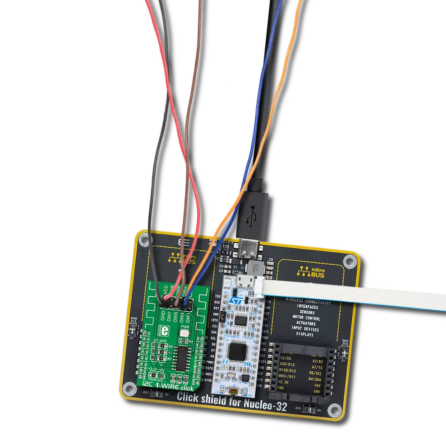
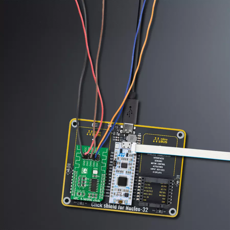
项目组装

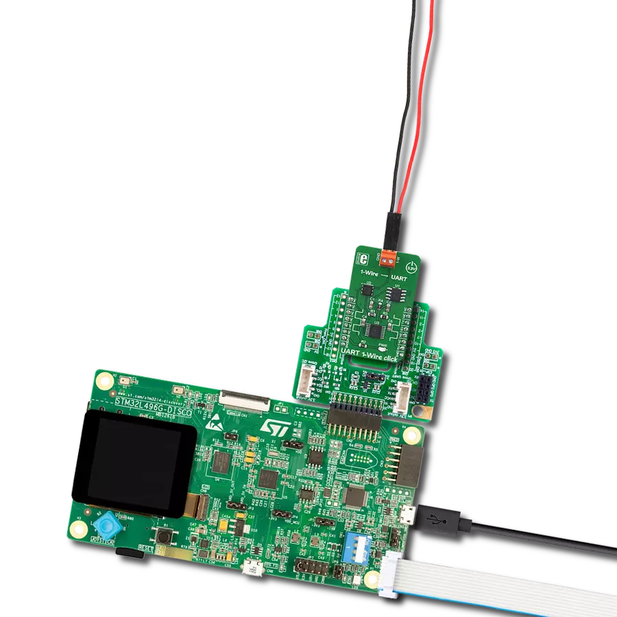
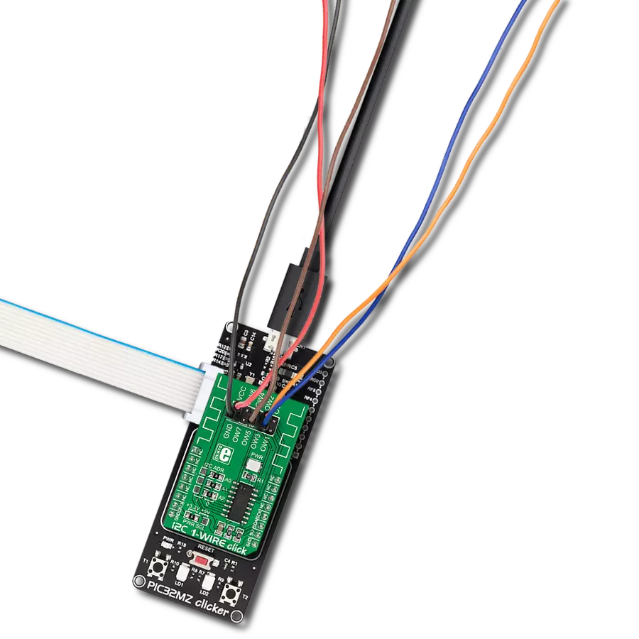
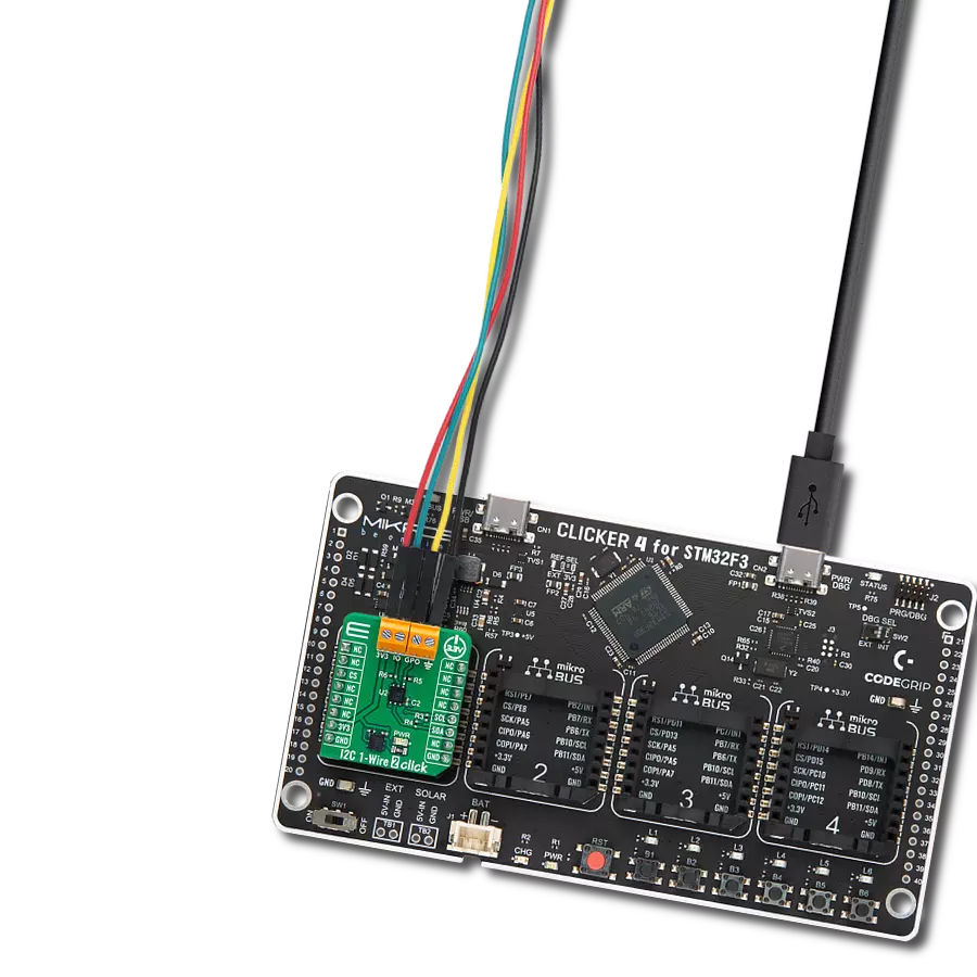
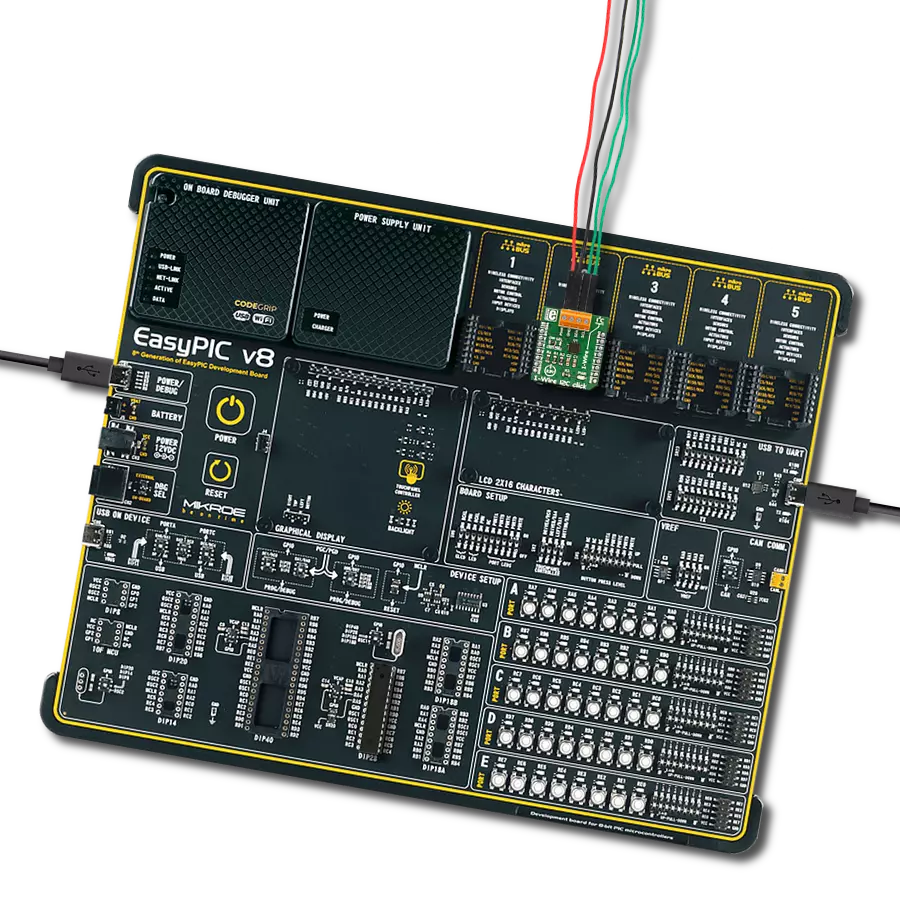
从选择您的开发板和Click板™开始。以Nucleo 32 with STM32F031K6 MCU作为您的开发板开始。


软件支持
库描述
这个库包含 I2C 1-Wire Click 驱动程序的 API
关键功能:
i2conewire_setChannel- 设置通道功能。i2conewire_writeByteOneWire- 通用的单线写入数据字节函数。i2conewire_readByteOneWire- 通用的单线读取数据字节函数。
开源
代码示例
完整的应用程序代码和一个现成的项目可以通过NECTO Studio包管理器直接安装到NECTO Studio。 应用程序代码也可以在MIKROE的GitHub账户中找到。
/*!
 * \file
 * \brief I2C1Wire Click example
 *
 * # Description
 * This example showcases how to initialize, confiure and use the I2C 1-Wire Click. The Click
 * is a I2C (host) to 1-Wire interface (slave). In order for the example to work one or more
 * 1-Wire (GPIO) Click modules are required. Gnd goes to gnd, power goes to power and the cha-
 * nnels are there to read data from connected modules.
 *
 * The demo application is composed of two sections :
 *
 * ## Application Init
 * This function initializes and configures the logger and Click modules.
 *
 * ## Application Task
 * This function reads all of the channels on the Click module and displays any data it acqu-
 * ires from them with a 100 millisecond delay.
 *
 *
 * \author MikroE Team
 *
 */
// ------------------------------------------------------------------- INCLUDES

#include "board.h"
#include "log.h"
#include "i2c1wire.h"

// ------------------------------------------------------------------ VARIABLES

static i2c1wire_t i2c1wire;
static log_t logger;

// ------------------------------------------------------ APPLICATION FUNCTIONS

void application_init ( )
{
    log_cfg_t log_cfg;
    i2c1wire_cfg_t cfg;

    /**
     * Logger initialization.
     * Default baud rate: 115200
     * Default log level: LOG_LEVEL_DEBUG
     * @note If USB_UART_RX and USB_UART_TX
     * are defined as HAL_PIN_NC, you will
     * need to define them manually for log to work.
     * See @b LOG_MAP_USB_UART macro definition for detailed explanation.
     */
    LOG_MAP_USB_UART( log_cfg );
    log_init( &logger, &log_cfg );
    log_info( &logger, "---- Application Init ----" );

    //  Click initialization.
    i2c1wire_cfg_setup( &cfg );
    I2C1WIRE_MAP_MIKROBUS( cfg, MIKROBUS_1 );
    i2c1wire_init( &i2c1wire, &cfg );
    Delay_1sec( );
}

void application_task ( )
{
    uint8_t chan_state = 0;
    uint8_t cnt_chan = 0;
    uint8_t cnt_val = 0;
    uint8_t id_code[ 9 ] = { 0 };

    chan_state = 1;

    i2c1wire_soft_reset( &i2c1wire );
    Delay_10ms( );
    i2c1wire_set_config( &i2c1wire, I2C1WIRE_CONFIG_1WS_HIGH |
                                    I2C1WIRE_CONFIG_SPU_HIGH |
                                    I2C1WIRE_CONFIG_APU_LOW );
    Delay_10ms( );

    for ( cnt_chan = 0; cnt_chan < 8; cnt_chan++ )
    {
        i2c1wire_set_channel( &i2c1wire, cnt_chan );
        i2c1wire_one_wire_reset( &i2c1wire );
        Delay_10ms( );

        i2c1wire_write_byte_one_wire( &i2c1wire, I2C1WIRE_WIRE_COMMAND_READ_ROM );
        Delay_10ms();

        for ( cnt_val = 8; cnt_val > 0; cnt_val-- )
        {
            id_code[ cnt_val ] = i2c1wire_read_byte_one_wire( &i2c1wire );

            if ( id_code[ cnt_val ] == I2C1WIRE_WIRE_RESULT_OK )
            {
                log_printf( &logger, "\r\n Channel %d : No device on the channel\r\n", ( uint16_t ) cnt_chan );
                Delay_100ms( );
                break;
            }
            else if ( chan_state )
            {
                log_printf( &logger, " Channel %d : ID = 0x", ( uint16_t ) cnt_chan );
                chan_state = 0;
            }

            log_printf( &logger, "%d", ( uint16_t ) id_code[ cnt_val ] );
            Delay_10ms( );
        }

        log_printf( &logger, "\r\n---------------------------------------\r\n" );
    }

    log_printf( &logger, "***\r\n" );
}

int main ( void )
{
    /* Do not remove this line or clock might not be set correctly. */
    #ifdef PREINIT_SUPPORTED
    preinit();
    #endif

    application_init( );

    for ( ; ; )
    {
        application_task( );
    }

    return 0;
}

// ------------------------------------------------------------------------ END
额外支持
资源
类别:单线