使用MAX7219和ATmega328P体验双LED矩阵显示控制的便捷
双倍冲击力:释放红色矩阵的魔力!

已发布 6月 24, 2024
点击板
Matrix R Click
开发板
Arduino UNO Rev3
编译器
NECTO Studio
微控制器单元
ATmega328P
我们的解决方案专为控制两个板载红色5x7矩阵而量身定制,提供无缝集成和创造自定义视觉效果、消息和通知的能力,以满足您的项目需求。
A
A
硬件概览
它是如何工作的?
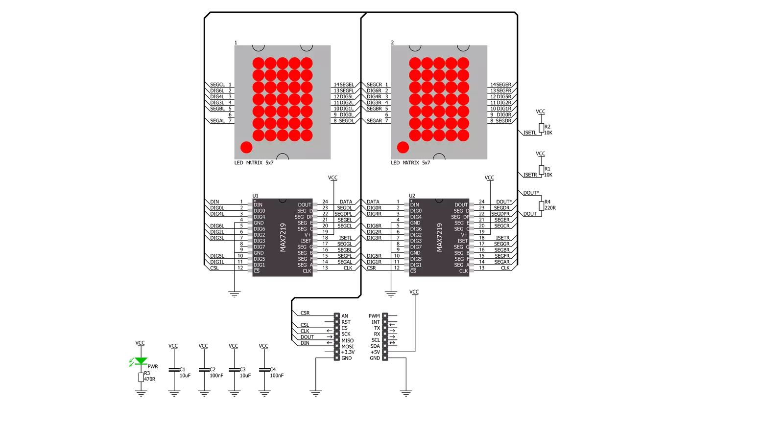
Matrix R Click基于两个来自Analog Devices的MAX7219,串行接口,8位LED显示驱动器。MAX7219通过10MHz串行接口可以单独或同时地址两个板载红色5x7点阵的每个LED。它具有数字和模拟亮度控制、上电序列空白显示、低功耗关闭并保留数据等功能。它还包括BCD代码-B解码器、多路复用扫描电路、段和数位驱动器,以及存储每个数据的8x8静态RAM。用户如果在具有两个相邻mikroBUS™插座的板
上进行双倍扩展,例如Fusion、Clicker 2或Flip&Click,就可以获得四个字符的显示。Matrix R Click使用SPI串行接口与主机微控制器通信,速度高达10MHz。每个MAX7219的片选引脚都连接到相应的mikroBUS™插座上的引脚。控制左侧显示的MAX7219连接到标记为CSL的引脚,而右侧连接到标记为CSR的引脚。在相应的片选引脚处于低电平状态时,串行数据被加载到移位寄存器中。峰值段电流通
过外部电阻设置为约40mA。显示的亮度可以通过软件中的内部PWM进行控制。此Click board™只能使用5V逻辑电压电平进行操作。在使用具有不同逻辑电平的MCU之前,必须对电路板执行适当的逻辑电压电平转换。此外,它配备了包含函数和示例代码的库,可用作进一步开发的参考。


功能概述
开发板
Arduino UNO 是围绕 ATmega328P 芯片构建的多功能微控制器板。它为各种项目提供了广泛的连接选项,具有 14 个数字输入/输出引脚,其中六个支持 PWM 输出,以及六个模拟输入。其核心组件包括一个 16MHz 的陶瓷谐振器、一个 USB 连接器、一个电
源插孔、一个 ICSP 头和一个复位按钮,提供了为板 子供电和编程所需的一切。UNO 可以通过 USB 连接到计算机,也可以通过 AC-to-DC 适配器或电池供电。作为第一个 USB Arduino 板,它成为 Arduino 平台的基准,"Uno" 符号化其作为系列首款产品的地
位。这个名称选择,意为意大利语中的 "一",是为了 纪念 Arduino Software(IDE)1.0 的推出。最初与 Arduino Software(IDE)版本1.0 同时推出,Uno 自此成为后续 Arduino 发布的基础模型,体现了该平台的演进。

微控制器概述
MCU卡片 / MCU

建筑
AVR
MCU 内存 (KB)
32
硅供应商
Microchip
引脚数
28
RAM (字节)
2048
你完善了我!
配件
Click Shield for Arduino UNO 具有两个专有的 mikroBUS™ 插座,使所有 Click board™ 设备能够轻松与 Arduino UNO 板进行接口连接。Arduino UNO 是一款基于 ATmega328P 的微控制器开发板,为用户提供了一种经济实惠且灵活的方式来测试新概念并构建基于 ATmega328P 微控制器的原型系统,结合了性能、功耗和功能的多种配置选择。Arduino UNO 具有 14 个数字输入/输出引脚(其中 6 个可用作 PWM 输出)、6 个模拟输入、16 MHz 陶瓷谐振器(CSTCE16M0V53-R0)、USB 接口、电源插座、ICSP 头和复位按钮。大多数 ATmega328P 微控制器的引脚都连接到开发板左右两侧的 IO 引脚,然后再连接到两个 mikroBUS™ 插座。这款 Click Shield 还配备了多个开关,可执行各种功能,例如选择 mikroBUS™ 插座上模拟信号的逻辑电平,以及选择 mikroBUS™ 插座本身的逻辑电压电平。此外,用户还可以通过现有的双向电平转换电压转换器使用任何 Click board™,无论 Click board™ 运行在 3.3V 还是 5V 逻辑电压电平。一旦将 Arduino UNO 板与 Click Shield for Arduino UNO 连接,用户即可访问数百种 Click board™,并兼容 3.3V 或 5V 逻辑电压电平的设备。

使用的MCU引脚
mikroBUS™映射器
“仔细看看!”
Click board™ 原理图
一步一步来
项目组装

从选择您的开发板和Click板™开始。以Arduino UNO Rev3作为您的开发板开始。


实时跟踪您的结果
应用程序输出
1. 应用程序输出 - 在调试模式下,“应用程序输出”窗口支持实时数据监控,直接提供执行结果的可视化。请按照提供的教程正确配置环境,以确保数据正确显示。

2. UART 终端 - 使用UART Terminal通过USB to UART converter监视数据传输,实现Click board™与开发系统之间的直接通信。请根据项目需求配置波特率和其他串行设置,以确保正常运行。有关分步设置说明,请参考提供的教程。

3. Plot 输出 - Plot功能提供了一种强大的方式来可视化实时传感器数据,使趋势分析、调试和多个数据点的对比变得更加直观。要正确设置,请按照提供的教程,其中包含使用Plot功能显示Click board™读数的分步示例。在代码中使用Plot功能时,请使用以下函数:plot(insert_graph_name, variable_name);。这是一个通用格式,用户需要将“insert_graph_name”替换为实际图表名称,并将“variable_name”替换为要显示的参数。

软件支持
库描述
这个库包含了Matrix R Click驱动的API。
关键功能:
matrixr_display_characters- 这个功能在点击的L/R段上显示指定的字符。matrixr_set_csn_high- 这个功能将CSN引脚输出设置为高。matrixr_set_csn_low- 这个功能将CSN引脚输出设置为低。
开源
代码示例
完整的应用程序代码和一个现成的项目可以通过NECTO Studio包管理器直接安装到NECTO Studio。 应用程序代码也可以在MIKROE的GitHub账户中找到。
/*!
 * @file main.c
 * @brief MatrixR Click example
 *
 * # Description
 * This example showcases how to prepare the logger and click modules for use and
 * how to display ASCII characters on both of the LED segments of the click.
 *
 * The demo application is composed of two sections :
 *
 * ## Application Init
 * This function initializes and configures the logger and click modules. After the initialization of the logger module,
 * communication, mikrobus and pin setup, some of the registers are configured in order for the click module to work properly.
 *
 * ## Application Task
 * This function displays two strings on each of the LED segments, showing one character every second.
 * It should display " Mikroelektronika" on the left one and "Mikroelektronika " on the right.
 *
 * @note
 * The click has two chips, each controlling one of the LED segments, on and requires you to write data to both at the same time.
 * Writing to one specific chip will not work. If you wish to display characters on a single segment, you have to send ' ' characters to the other segment.
 *
 * @author Jelena Milosavljevic
 *
 */

// ------------------------------------------------------------------- INCLUDES

#include "board.h"
#include "log.h"
#include "matrixr.h"

// ------------------------------------------------------------------ VARIABLES

static matrixr_t matrixr;
static log_t logger;

// ------------------------------------------------------ APPLICATION FUNCTIONS

void application_init ( ) {

    log_cfg_t log_cfg;
    matrixr_cfg_t cfg;

    /**
     * Logger initialization.
     * Default baud rate: 115200
     * Default log level: LOG_LEVEL_DEBUG
     * @note If USB_UART_RX and USB_UART_TX
     * are defined as HAL_PIN_NC, you will
     * need to define them manually for log to work.
     * See @b LOG_MAP_USB_UART macro definition for detailed explanation.
     */
    LOG_MAP_USB_UART( log_cfg );
    log_init( &logger, &log_cfg );
    log_info( &logger, "---- Application Init ----" );

    //  Click initialization.

    matrixr_cfg_setup( &cfg );
    MATRIXR_MAP_MIKROBUS( cfg, MIKROBUS_1 );
    matrixr_init( &matrixr, &cfg );
    Delay_ms( 100 );
    matrixr_default_cfg( &matrixr );
    Delay_ms( 100 );
}

void application_task ( ) {

    matrixr_display_characters( &matrixr, ' ', 'M' );
    Delay_ms( 1000 );
    matrixr_display_characters( &matrixr, 'M', 'i' );
    Delay_ms( 1000 );
    matrixr_display_characters( &matrixr, 'i', 'k' );
    Delay_ms( 1000 );
    matrixr_display_characters( &matrixr, 'k', 'r' );
    Delay_ms( 1000);
    matrixr_display_characters( &matrixr, 'r', 'o' );
    Delay_ms( 1000 );
    matrixr_display_characters( &matrixr, 'o', 'E' );
    Delay_ms( 1000 );
    matrixr_display_characters( &matrixr, 'E', 'l' );
    Delay_ms( 1000 );
    matrixr_display_characters( &matrixr, 'l', 'e' );
    Delay_ms( 1000 );
    matrixr_display_characters( &matrixr, 'e', 'k' );
    Delay_ms( 1000 );
    matrixr_display_characters( &matrixr, 'k', 't' );
    Delay_ms( 1000 );
    matrixr_display_characters( &matrixr, 't', 'r' );
    Delay_ms( 1000 );
    matrixr_display_characters( &matrixr, 'r', 'o' );
    Delay_ms( 1000 );
    matrixr_display_characters( &matrixr, 'o', 'n' );
    Delay_ms( 1000 );
    matrixr_display_characters( &matrixr, 'n', 'i' );
    Delay_ms( 1000 );
    matrixr_display_characters( &matrixr, 'i', 'k' );
    Delay_ms( 1000 );
    matrixr_display_characters( &matrixr, 'k', 'a' );
    Delay_ms( 100 );
    matrixr_display_characters( &matrixr, 'a', ' ' );
    Delay_ms( 100 );
}

void main ( ) {

    application_init( );

    for ( ; ; )
    {
        application_task( );
    }
}

// ------------------------------------------------------------------------ END


