使用WIRL-PRO2和ATmega328将Wirepas Mesh无线连接堆栈集成到您的应用中
Wirepas Click 立刻行动!

已发布 6月 27, 2024
点击板
Wirepas Click
开发板
Arduino UNO Rev3
编译器
NECTO Studio
微控制器单元
ATmega328
您的网关可以创建坚固的、自愈的和节能的网状网络,适用于智能照明、资产追踪等应用!
A
A
硬件概览
它是如何工作的?
Wirepas Click 基于 Würth Elektronik 的 WIRL-PRO2 Thetis-I,这是一款带有 Wirepas Mesh 协议的无线电模块。该模块旨在集成到基于 Wirepas 的路由网络中,用于设备或节点之间的无线通信。该模块在全球可用的免许可 2.4 GHz 频段内安全可靠地传输数据,具有认证和加密机制。WIRL-PRO2 Thetis-I 模块具有与 nano-SIM 卡相当的小尺寸(8 mm x 12 mm),包括板载 PCB 天线,使其非常适合小型设计。该模块工作在 2402 到 2480MHz 的频率范围内,数据速率高达 1Mbps。它基于 Nordic
Semiconductor 的 32 位 ARM Cortex-M4 微控制器 nRF52840,配有 1MB 闪存和 256KB RAM。它具有印刷天线和智能天线配置(2 合 1 模块),允许高达 +6dBm 的发射功率和 -92dBm 的灵敏度。通过连接到板载 N.FL 连接器的外部天线,连接性能可以更好。由于其非常低的功耗,Wirepas Click 可以作为信标使用。为此,它配备了一个备用电池。此外,还有两个用户可配置的指示 LED,LED1 和 LED2(蓝色和绿色)。此外,Wirepas Click 还配备了一个未焊接的调试头,用于与 Wirepas 微控制器进行直接
通信。Wirepas Click 使用标准的 2 线 UART 接口与主 MCU 通信,支持 115200bps 的比特率。您可以通过 RST 引脚重置设备。DIN 引脚用于观察数据流,当处于低电平逻辑状态时,它是指向主 MCU 的数据指示。此 Click board™ 只能在 3.3V 逻辑电压水平下运行。使用具有不同逻辑电平的 MCU 之前,板必须进行适当的逻辑电压水平转换。此外,这款 Click board™ 配备了包含易于使用的功能和示例代码的库,可用于进一步开发。

功能概述
开发板
Arduino UNO 是围绕 ATmega328P 芯片构建的多功能微控制器板。它为各种项目提供了广泛的连接选项,具有 14 个数字输入/输出引脚,其中六个支持 PWM 输出,以及六个模拟输入。其核心组件包括一个 16MHz 的陶瓷谐振器、一个 USB 连接器、一个电
源插孔、一个 ICSP 头和一个复位按钮,提供了为板 子供电和编程所需的一切。UNO 可以通过 USB 连接到计算机,也可以通过 AC-to-DC 适配器或电池供电。作为第一个 USB Arduino 板,它成为 Arduino 平台的基准,"Uno" 符号化其作为系列首款产品的地
位。这个名称选择,意为意大利语中的 "一",是为了 纪念 Arduino Software(IDE)1.0 的推出。最初与 Arduino Software(IDE)版本1.0 同时推出,Uno 自此成为后续 Arduino 发布的基础模型,体现了该平台的演进。

微控制器概述
MCU卡片 / MCU

建筑
AVR
MCU 内存 (KB)
32
硅供应商
Microchip
引脚数
32
RAM (字节)
2048
你完善了我!
配件
Click Shield for Arduino UNO 具有两个专有的 mikroBUS™ 插座,使所有 Click board™ 设备能够轻松与 Arduino UNO 板进行接口连接。Arduino UNO 是一款基于 ATmega328P 的微控制器开发板,为用户提供了一种经济实惠且灵活的方式来测试新概念并构建基于 ATmega328P 微控制器的原型系统,结合了性能、功耗和功能的多种配置选择。Arduino UNO 具有 14 个数字输入/输出引脚(其中 6 个可用作 PWM 输出)、6 个模拟输入、16 MHz 陶瓷谐振器(CSTCE16M0V53-R0)、USB 接口、电源插座、ICSP 头和复位按钮。大多数 ATmega328P 微控制器的引脚都连接到开发板左右两侧的 IO 引脚,然后再连接到两个 mikroBUS™ 插座。这款 Click Shield 还配备了多个开关,可执行各种功能,例如选择 mikroBUS™ 插座上模拟信号的逻辑电平,以及选择 mikroBUS™ 插座本身的逻辑电压电平。此外,用户还可以通过现有的双向电平转换电压转换器使用任何 Click board™,无论 Click board™ 运行在 3.3V 还是 5V 逻辑电压电平。一旦将 Arduino UNO 板与 Click Shield for Arduino UNO 连接,用户即可访问数百种 Click board™,并兼容 3.3V 或 5V 逻辑电压电平的设备。

使用的MCU引脚
mikroBUS™映射器
“仔细看看!”
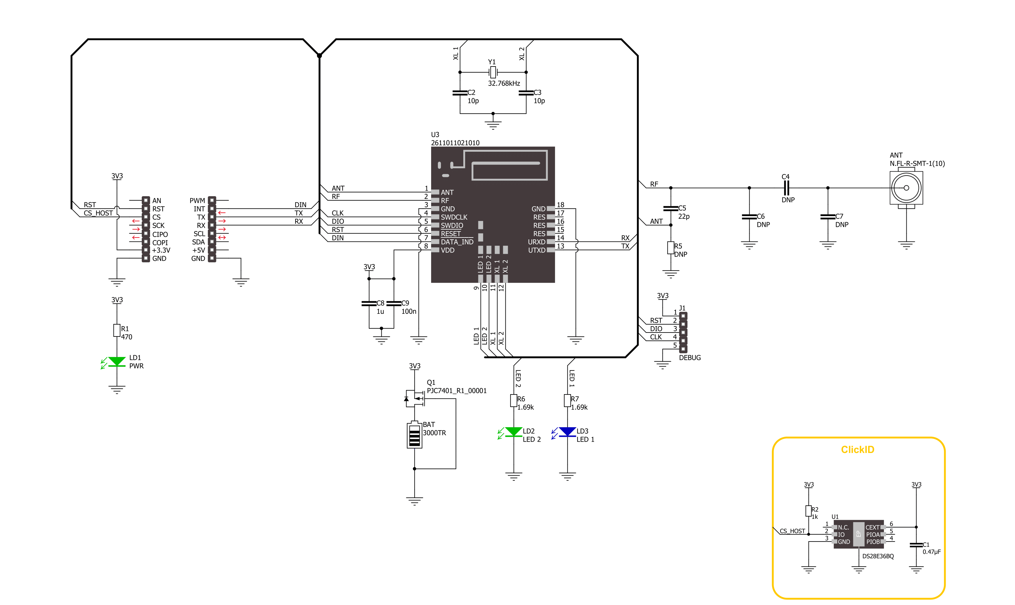
Click board™ 原理图
一步一步来
项目组装

从选择您的开发板和Click板™开始。以Arduino UNO Rev3作为您的开发板开始。


实时跟踪您的结果
应用程序输出
1. 应用程序输出 - 在调试模式下,“应用程序输出”窗口支持实时数据监控,直接提供执行结果的可视化。请按照提供的教程正确配置环境,以确保数据正确显示。

2. UART 终端 - 使用UART Terminal通过USB to UART converter监视数据传输,实现Click board™与开发系统之间的直接通信。请根据项目需求配置波特率和其他串行设置,以确保正常运行。有关分步设置说明,请参考提供的教程。

3. Plot 输出 - Plot功能提供了一种强大的方式来可视化实时传感器数据,使趋势分析、调试和多个数据点的对比变得更加直观。要正确设置,请按照提供的教程,其中包含使用Plot功能显示Click board™读数的分步示例。在代码中使用Plot功能时,请使用以下函数:plot(insert_graph_name, variable_name);。这是一个通用格式,用户需要将“insert_graph_name”替换为实际图表名称,并将“variable_name”替换为要显示的参数。

软件支持
库描述
该库包含 Wirepas Click 驱动程序的 API。
关键功能:
wirepas_send_command- Wirepas 发送命令功能。wirepas_write_csap_attribute- Wirepas 写入 CSAP 属性功能。wirepas_send_data- Wirepas 发送数据功能。
开源
代码示例
完整的应用程序代码和一个现成的项目可以通过NECTO Studio包管理器直接安装到NECTO Studio。 应用程序代码也可以在MIKROE的GitHub账户中找到。
/*!
 * @file main.c
 * @brief Wirepas Click Example.
 *
 * # Description
 * This example demonstrates the use of Wirepas click board by processing
 * the incoming data and displaying them on the USB UART in sink mode, and sending data to
 * the sinks in router mode.
 *
 * The demo application is composed of two sections :
 *
 * ## Application Init
 * Initializes the driver and performs the click default configuration, setting device mode, node,
 * net and channel addresses, and starting stack.
 *
 * ## Application Task
 * Router mode - Sending data to the sinks at the same network.
 * Sink mode - Reads and processes all incoming data and displays them on the USB UART.
 *
 * ## Additional Function
 * - err_t wirepas_get_resp ( wirepas_t *ctx )
 *
 * @note
 * For the best experience use two clicks in sink mode and one in router.
 *
 * @author Stefan Ilic
 *
 */

#include "board.h"
#include "log.h"
#include "wirepas.h"

#define PROCESS_BUFFER_SIZE 200
#define TX_DATA             "Wirepas Click"

#define MULTI_SINK_MODE     // Comment out this macro to place device into single sink mode.

/**
* @brief Wirepas node addresses.
 * @details Specified setting for node addresses of Wirepas Click driver.
 */
#define ROUTER_NODE_ADDRESS         0x01
#define SINK_1_NODE_ADDRESS         0x02
#define SINK_2_NODE_ADDRESS         0x03
#define NET_ADDRESS                 0x01
#define CHANNEL_ADDRESS             0x01

#define NODE_ADDRESS                ROUTER_NODE_ADDRESS    /* Change the value of this macro to change
                                                              node address, each node should have a unique address */

static wirepas_t wirepas;
static log_t logger;
uint8_t frame_id = 0;
wirepas_sink_data sink_1;
wirepas_sink_data sink_2;

/**
 * @brief Wirepas get response function.
 * @details This function is used to get response from the device.
 * @param[in] ctx : Click context object.
 * See #wirepas_t object definition for detailed explanation.
 * @return @li @c  >=0 - Success,
 *         @li @c   <0 - Error.
 * See #err_t definition for detailed explanation.
 * @note None.
 */
err_t wirepas_get_resp ( wirepas_t *ctx );

void application_init ( void )
{
    log_cfg_t log_cfg;  /**< Logger config object. */
    wirepas_cfg_t wirepas_cfg;  /**< Click config object. */

    /**
     * Logger initialization.
     * Default baud rate: 115200
     * Default log level: LOG_LEVEL_DEBUG
     * @note If USB_UART_RX and USB_UART_TX
     * are defined as HAL_PIN_NC, you will
     * need to define them manually for log to work.
     * See @b LOG_MAP_USB_UART macro definition for detailed explanation.
     */
    LOG_MAP_USB_UART( log_cfg );
    log_init( &logger, &log_cfg );
    log_info( &logger, " Application Init " );

    // Click initialization.
    wirepas_cfg_setup( &wirepas_cfg );
    WIREPAS_MAP_MIKROBUS( wirepas_cfg, MIKROBUS_1 );
    if ( UART_ERROR == wirepas_init( &wirepas, &wirepas_cfg ) )
    {
        log_error( &logger, " Communication init." );
        for ( ; ; );
    }

    wirepas_default_cfg ( &wirepas );

    uint8_t tmp_data[ 1 ] = { 0x00 };

    Delay_ms( 1000 );
    wirepas_poll_indication( &wirepas, frame_id, NULL, NULL );
    frame_id++;

    Delay_ms( 1000 );
    wirepas_poll_indication( &wirepas, frame_id, NULL, NULL );
    frame_id++;

    Delay_ms( 1000 );
    log_printf( &logger, " Wirepas stack stop request: \n" );
    wirepas_send_command( &wirepas, WIREPAS_MSAP_STACK_STOP_REQUEST, frame_id, 0x00, tmp_data );
    frame_id++;
    wirepas_get_resp( &wirepas );

    Delay_ms( 1000 );
    log_printf( &logger, " Wirepas factory reset request: \n" );
    wirepas_send_command( &wirepas, WIREPAS_CSAP_FACTORY_RESET_REQUEST, frame_id, strlen( WIREPAS_FACTORY_RESET_CODE ), WIREPAS_FACTORY_RESET_CODE );
    frame_id++;
    wirepas_get_resp( &wirepas );

    Delay_ms( 1000 );
    wirepas_poll_indication( &wirepas, frame_id, NULL, NULL );
    frame_id++;

    Delay_ms( 1000 );
    wirepas_poll_indication( &wirepas, frame_id, NULL, NULL );
    frame_id++;

    Delay_ms( 1000 );
    log_printf( &logger, " Set node address: \n" );
    wirepas_set_node_address( &wirepas, frame_id, NODE_ADDRESS );
    frame_id++;
    wirepas_get_resp( &wirepas );

    Delay_ms( 1000 );
    log_printf( &logger, " Set net address: \n" );
    wirepas_set_net_address( &wirepas, frame_id, NET_ADDRESS );
    frame_id++;
    wirepas_get_resp( &wirepas );

    Delay_ms( 1000 );
    log_printf( &logger, " Set channel address: \n" );
    uint8_t channel_net = CHANNEL_ADDRESS;
    wirepas_write_csap_attribute( &wirepas, frame_id, WIREPAS_CSAP_ATTRIBUTE_NETWORK_CHANNEL, 1, &channel_net );
    frame_id++;
    wirepas_get_resp( &wirepas );

    Delay_ms( 1000 );
    log_printf( &logger, " Set role: \n" );
    uint8_t role;
#if ( ROUTER_NODE_ADDRESS == NODE_ADDRESS )
    role = WIREPAS_ROUTER_NODE_MODE;
#else
    role = WIREPAS_SINK_NODE_MODE;
#endif
    wirepas_write_csap_attribute( &wirepas, frame_id, WIREPAS_CSAP_ATTRIBUTE_NODE_ROLE, 1, &role );
    frame_id++;
    wirepas_get_resp( &wirepas );

    Delay_ms( 1000 );
    log_printf( &logger, " Wirepas Stack start request: \n" );
    tmp_data[ 0 ] = 0x01;
    wirepas_send_command( &wirepas, WIREPAS_MSAP_STACK_START_REQUEST, frame_id, 0x01, tmp_data );
    frame_id++;
    wirepas_get_resp( &wirepas );

    uint8_t data_buf[ WIREPAS_RX_DRV_BUFFER_SIZE ] = { 0 };

#if ( ROUTER_NODE_ADDRESS == NODE_ADDRESS )
    Delay_ms( 1000 );
    wirepas_poll_indication( &wirepas, frame_id, data_buf, NULL );
    frame_id++;

    sink_1.pduid = 0x00;
    sink_1.source_endpoint = 0x01;
    sink_1.destination_addr = SINK_1_NODE_ADDRESS;
    sink_1.destination_endpoint = 0x01;
    #if defined MULTI_SINK_MODE
        sink_2.pduid = 0x00;
        sink_2.source_endpoint = 0x01;
        sink_2.destination_addr = SINK_2_NODE_ADDRESS;
        sink_2.destination_endpoint = 0x01;
    #endif
#else
    uint8_t data_rd = 0;
    while ( 0 == data_rd )
    {
        wirepas_poll_indication( &wirepas, frame_id, data_buf, &data_rd );
        frame_id++;
        Delay_ms( 1000 );
    }
#endif
    Delay_ms( 100 );

    log_info( &logger, " Application Task " );
}

void application_task ( void )
{
#if ( ROUTER_NODE_ADDRESS == NODE_ADDRESS )
    log_printf( &logger, " Sending data to the first Sink node: \n" );
    wirepas_send_data ( &wirepas, frame_id, sink_1, 0x01, strlen( TX_DATA ), TX_DATA );
    frame_id++;
    wirepas_get_resp( &wirepas );
    Delay_ms( 5000 );

    #if defined MULTI_SINK_MODE
        log_printf( &logger, " Sending data to the second Sink node: \n" );
        wirepas_send_data ( &wirepas, frame_id, sink_2, 0x01, strlen( TX_DATA ), TX_DATA );
        frame_id++;
        wirepas_get_resp( &wirepas );
        Delay_ms( 5000 );
    #endif
#else
    uint8_t data_buf[ WIREPAS_RX_DRV_BUFFER_SIZE ] = { 0 };
    uint8_t data_rdy = 0;
    err_t error = wirepas_poll_indication( &wirepas, frame_id, data_buf, &data_rdy );
    frame_id++;
    if ( 1 == data_rdy )
    {
        log_printf( &logger, "%s \r\n", data_buf );
    }
    Delay_ms( 2000 );
#endif
}

void main ( void )
{
    application_init( );

    for ( ; ; )
    {
        application_task( );
    }
}

err_t wirepas_get_resp ( wirepas_t *ctx )
{
    uint8_t rx_buf[ PROCESS_BUFFER_SIZE ] = { 0 };
    int32_t rx_size = 0;

    Delay_ms( 1000 );
    rx_size = wirepas_generic_read( ctx, rx_buf, PROCESS_BUFFER_SIZE );
    if ( rx_size > 0 )
    {
        if ( 0 == rx_buf[ 4 ] )
        {
            log_printf( &logger, " Response OK \n" );
            return WIREPAS_OK;
        }
        else
        {
            log_printf( &logger, " Response ERROR %d\n", rx_buf[ 4 ] );
            return WIREPAS_ERROR;
        }

    }

}

// ------------------------------------------------------------------------ END
额外支持
资源
类别:2.4 GHz 收发器


