使用STM32F103RB和PAM8904为各种事件或警报创建通知系统
引起注意的警报:重新定义信号的下一代蜂鸣器

已发布 10月 08, 2024
点击板
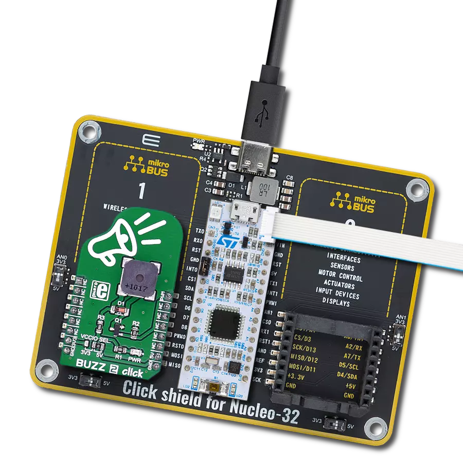
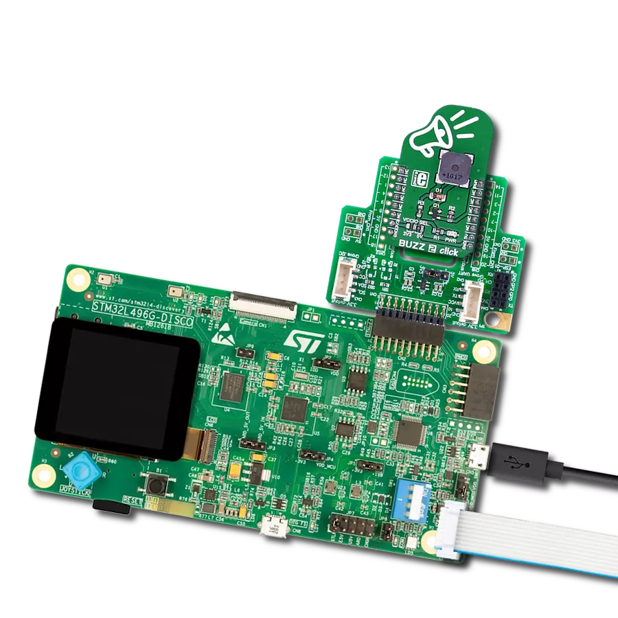
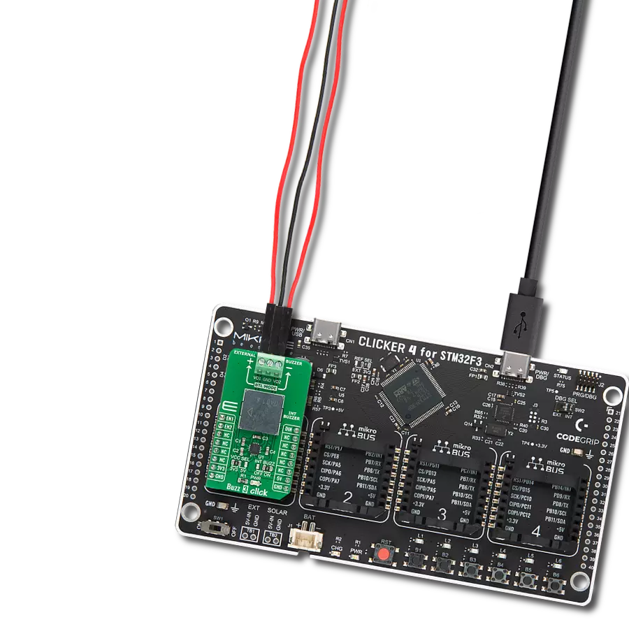
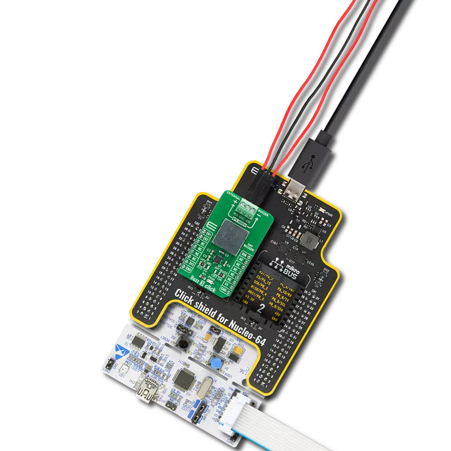
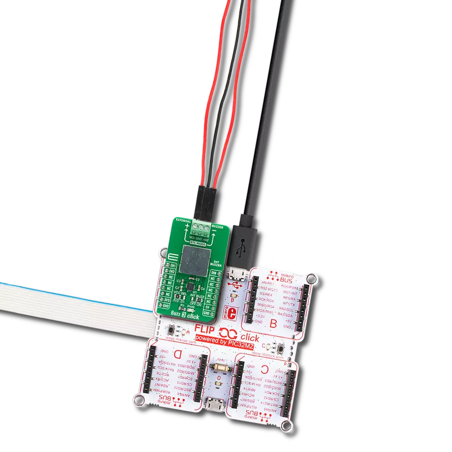
BUZZ 3 Click
开发板
Nucleo 64 with STM32F103RB MCU
编译器
NECTO Studio
微控制器单元
STM32F103RB
踏入音频信号的未来,体验新一代蜂鸣器在各行各业和各种环境中的变革性影响。
A
A
硬件概览
它是如何工作的?
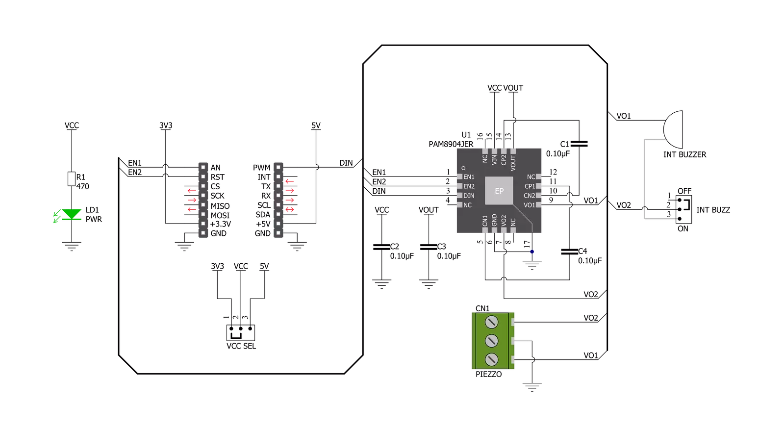
Buzz 3 Click 基于Diodes Incorporated的PAM8904,这是一款带集成多模式电荷泵升压转换器的压电发声器驱动器。PAM8904是一种开关驱动器,具有多模式电荷泵,用于压电发声器。PAM8904以固定频率1MHz工作,可以驱动高达15nF的发声器负载,提供9V输出,并具有最小的组件占用空间。为了调整压电发声器的音量,电荷泵可以在1x、2x或3x模式下工作。它具有热关断、过流和过压保护、欠压锁定等功能,提供小的浪涌电流、低EMI和高效率。发声器驱动器通过采用内置自动关断和唤醒功能,有助于保持低电流消耗和延长电池寿命。例如,在1x模式下,输入电压为3V、输入
频率为4kHz、驱动15nF压电发声器时,活动电流消耗仅为300µA。在关断模式下,静态电流小于1µA。电荷泵模式引脚EN1和EN2用于将电荷泵设置为1xVDD、2xVDD、3xVDD模式,或者用于将PAM8904置于强制低电流关断模式。当一个或两个EN引脚被拉高时,设备进入正常操作模式。一旦PAM8904检测到DIN引脚上有有效信号,电荷泵将启动并在VOUT引脚上提供所需电压,标记为VO1和VO2的输出驱动线将在270μs至350μs之间的时间内变为活动状态,具体取决于所选模式。如果DIN线上的有效信号消失,PAM8904将检测到该消失,然后等待42ms以确保其消失。如果即使在此期间
后,DIN线上仍没有有效信号,PAM8904将切换到低电流待机模式。Buzz 3 Click通过连接到mikroBUS™插座的RST、AN和PWM引脚(标记为EN1、EN2和DIN)的多个GPIO引脚与MCU建立通信。此外,还有一个标记为INT BUZZ的跳线设置,用于在单端和差分负载配置之间选择,以及驱动板载压电发声器或外部连接的压电发声器。此Click板™可以通过VCC SEL跳线选择3.3V或5V逻辑电压等级。这样,3.3V和5V能力的MCU都可以正确使用通信线。此外,该Click板™配备了一个包含易于使用功能和示例代码的库,可用作进一步开发的参考。

功能概述
开发板
Nucleo-64 搭载 STM32F103RB MCU 提供了一种经济高效且灵活的平台,供开发者探索新想法并原型设计他们的项目。该板利用 STM32 微控制器的多功能性,使用户能够为他们的项目选择最佳的性能与功耗平衡。它配备了 LQFP64 封装的 STM32 微控制器,并包含了如用户 LED(同时作为 ARDUINO® 信号)、用户和复位按钮,以及 32.768kHz 晶体振荡器用于精确的计时操作等基本组件。Nucleo-64 板设计考虑到扩展性和灵活性,它特有的 ARDUINO® Uno
V3 扩展连接器和 ST morpho 扩展引脚头,提供了对 STM32 I/O 的完全访问,以实现全面的项目整合。电源供应选项灵活,支持 ST-LINK USB VBUS 或外部电源,确保在各种开发环境中的适应性。该板还配备了一个具有 USB 重枚举功能的板载 ST-LINK 调试器/编程器,简化了编程和调试过程。此外,该板设计旨在简化高级开发,它的外部 SMPS 为 Vcore 逻辑供电提供高效支持,支持 USB 设备全速或 USB SNK/UFP 全速,并内置加密功能,提升了项目的功效
和安全性。通过外部 SMPS 实验的专用连接器、 用于 ST-LINK 的 USB 连接器以及 MIPI® 调试连接器,提供了更多的硬件接口和实验可能性。开发者将通过 STM32Cube MCU Package 提供的全面免费软件库和示例得到广泛支持。这些,加上与多种集成开发环境(IDE)的兼容性,包括 IAR Embedded Workbench®、MDK-ARM 和 STM32CubeIDE,确保了流畅且高效的开发体验,使用户能够充分利用 Nucleo-64 板在他们的项目中的能力。

微控制器概述
MCU卡片 / MCU

建筑
ARM Cortex-M3
MCU 内存 (KB)
128
硅供应商
STMicroelectronics
引脚数
64
RAM (字节)
20480
你完善了我!
配件
Click Shield for Nucleo-64 配备了两个专有的 mikroBUS™ 插座,使得所有的 Click board™ 设备都可以轻松地与 STM32 Nucleo-64 开发板连接。这样,Mikroe 允许其用户从不断增长的 Click boards™ 范围中添加任何功能,如 WiFi、GSM、GPS、蓝牙、ZigBee、环境传感器、LED、语音识别、电机控制、运动传感器等。您可以使用超过 1537 个 Click boards™,这些 Click boards™ 可以堆叠和集成。STM32 Nucleo-64 开发板基于 64 引脚封装的微控制器,采用 32 位 MCU,配备 ARM Cortex M4 处理器,运行速度为 84MHz,具有 512Kb Flash 和 96KB SRAM,分为两个区域,顶部区域代表 ST-Link/V2 调试器和编程器,而底部区域是一个实际的开发板。通过 USB 连接方便地控制和供电这些板子,以便直接对 Nucleo-64 开发板进行编程和高效调试,其中还需要额外的 USB 线连接到板子上的 USB 迷你接口。大多数 STM32 微控制器引脚都连接到了板子左右边缘的 IO 引脚上,然后连接到两个现有的 mikroBUS™ 插座上。该 Click Shield 还有几个开关,用于选择 mikroBUS™ 插座上模拟信号的逻辑电平和 mikroBUS™ 插座本身的逻辑电压电平。此外,用户还可以通过现有的双向电平转换器,使用任何 Click board™,无论 Click board™ 是否在 3.3V 或 5V 逻辑电压电平下运行。一旦将 STM32 Nucleo-64 开发板与我们的 Click Shield for Nucleo-64 连接,您就可以访问数百个工作于 3.3V 或 5V 逻辑电压电平的 Click boards™。

使用的MCU引脚
mikroBUS™映射器
“仔细看看!”
Click board™ 原理图
一步一步来
项目组装
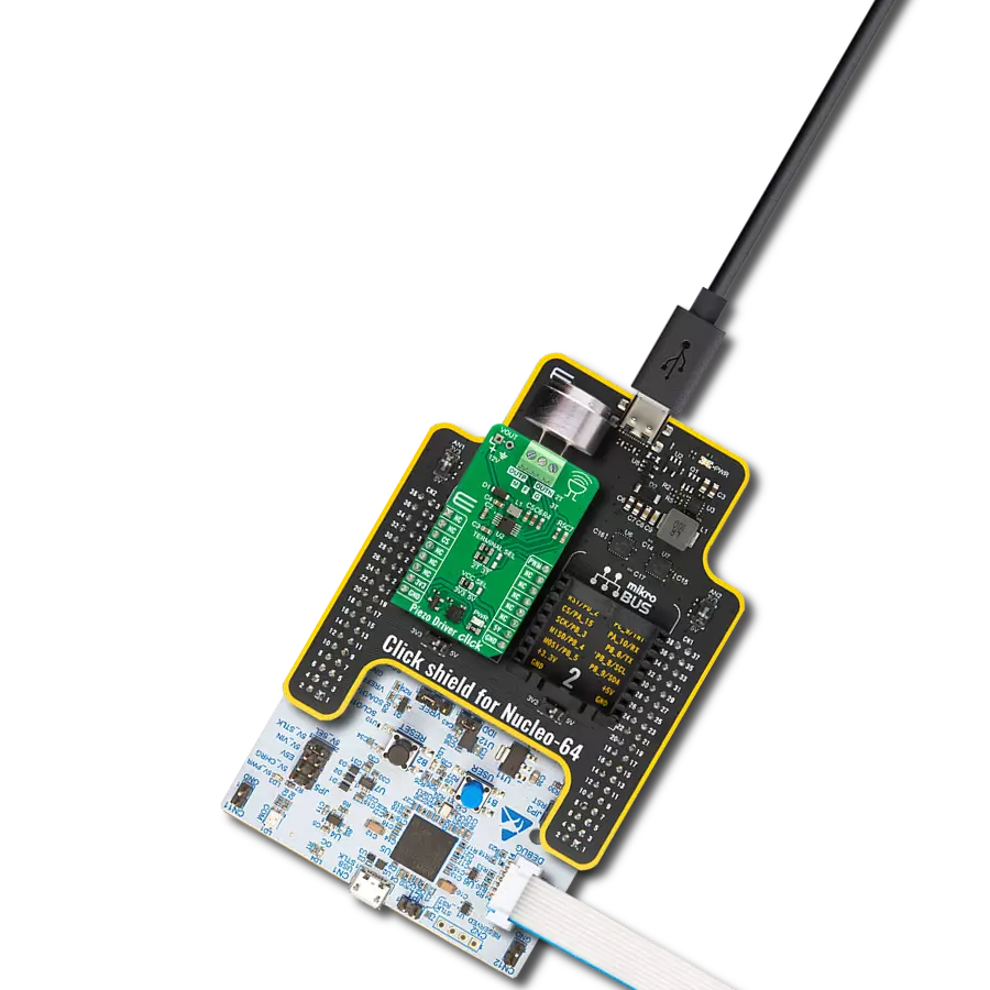
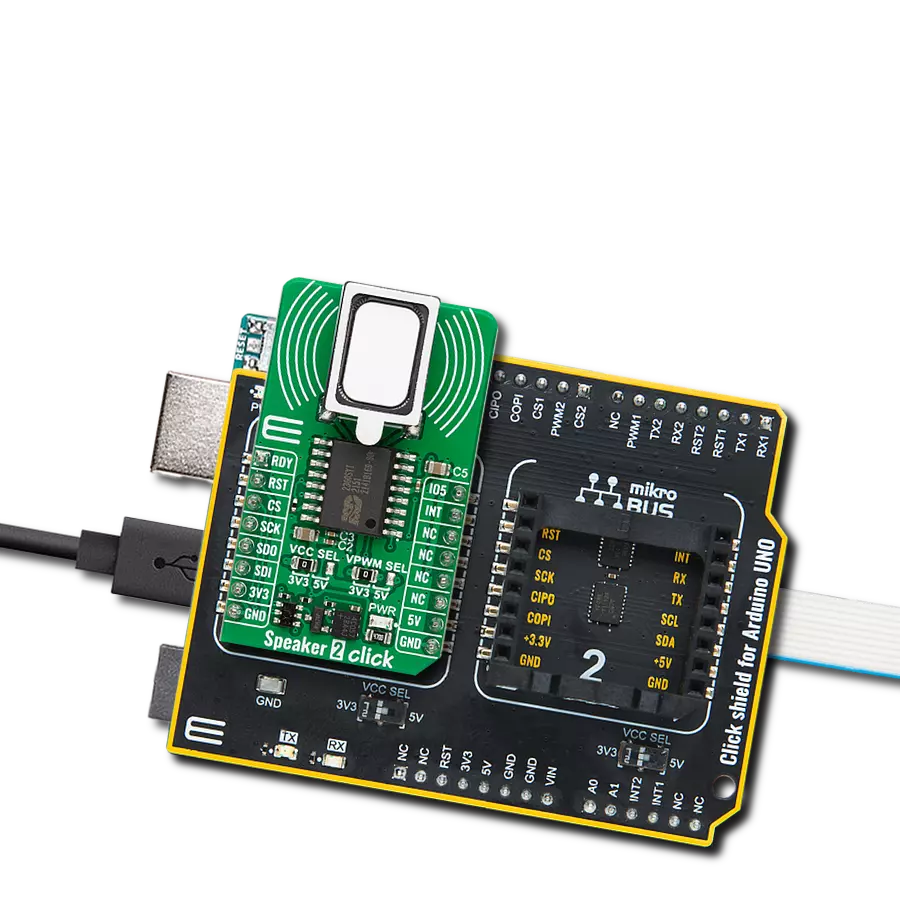
从选择您的开发板和Click板™开始。以Nucleo 64 with STM32F103RB MCU作为您的开发板开始。


软件支持
库描述
该库包含 Buzz 3 Click 驱动程序的 API。
关键功能:
buzz3_pwm_start- 此功能启动PWM模块输出buzz3_set_gain_operating_mode- 此功能设置Buzz 3 Click上带有集成升压转换器的PAM8904压电发声器驱动器的增益操作模式buzz3_play_sound- 此功能在蜂鸣器上播放声音
开源
代码示例
完整的应用程序代码和一个现成的项目可以通过NECTO Studio包管理器直接安装到NECTO Studio。 应用程序代码也可以在MIKROE的GitHub账户中找到。
/*!
 * @file main.c
 * @brief Buzz3 Click example
 *
 * # Description
 * This example demonstrates the use of Buzz 3 Click boards with PAM8904 for play the Imperial March.
 * PAM8904 is piezo-sounder driver with an integrated Multi-Mode charge pump boost converter from Diodes Incorporated.
 *
 * The demo application is composed of two sections :
 *
 * ## Application Init
 * Initializes GPIO, set AN and RST pin as outputs, begins to write a log.
 * Initialization driver enables - GPIO and configures the appropriate MCU pin for
 * sound generation, also write log.
 *
 * ## Application Task
 * Plays the Imperial March melody. Also logs an appropriate message on the USB UART.
 *
 * Additional Functions :
 * - void buzz3_melody( void ) - This function plays the Imperial March melody.
 *
 * @note
 * The minimal PWM Clock frequency required for this example is the frequency of tone C6 - 1047 Hz.
 * So, in order to run this example and play all tones correctly, the user will need to decrease
 * the MCU's main clock frequency in MCU Settings for the certain architectures
 * in order to get the required PWM clock frequency.
 *
 * @author Jelena Milosavljevic
 *
 */

#include "board.h"
#include "log.h"
#include "buzz3.h"

#define W 4*Q         // Whole 4/4 - 4 Beats
#define H 2*Q         // Half 2/4 - 2 Beats
#define Q 250         // Quarter 1/4 - 1 Beat
#define E Q/2         // Eighth 1/8 - 1/2 Beat
#define S Q/4         // Sixteenth 1/16 - 1/4 Beat


static buzz3_t buzz3;
static log_t logger;

void buzz3_melody ( void ) {
    buzz3_play_sound(&buzz3, BUZZ3_NOTE_A6, Q );
    Delay_ms ( 1 + Q );
    buzz3_play_sound(&buzz3, BUZZ3_NOTE_A6, Q );
    Delay_ms ( 1 + Q );
    buzz3_play_sound(&buzz3, BUZZ3_NOTE_A6, Q );
    Delay_ms ( 1 + Q );
    buzz3_play_sound(&buzz3, BUZZ3_NOTE_F6, E + S );
    Delay_ms ( 1 + E + S );
    buzz3_play_sound(&buzz3, BUZZ3_NOTE_C7, S );
    Delay_ms ( 1 + S );

    buzz3_play_sound(&buzz3, BUZZ3_NOTE_A6, Q );
    Delay_ms ( 1 + Q );
    buzz3_play_sound(&buzz3, BUZZ3_NOTE_F6, E + S );
    Delay_ms ( 1 + E + S );
    buzz3_play_sound(&buzz3, BUZZ3_NOTE_C7, S );
    Delay_ms ( 1 + S );
    buzz3_play_sound(&buzz3, BUZZ3_NOTE_A6, H );
    Delay_ms ( 1 + H );

    buzz3_play_sound(&buzz3, BUZZ3_NOTE_E7, Q );
    Delay_ms ( 1 + Q );
    buzz3_play_sound(&buzz3, BUZZ3_NOTE_E7, Q );
    Delay_ms ( 1 + Q );
    buzz3_play_sound(&buzz3, BUZZ3_NOTE_E7, Q );
    Delay_ms ( 1 + Q );
    buzz3_play_sound(&buzz3, BUZZ3_NOTE_F7, E + S );
    Delay_ms ( 1 + E + S );
    buzz3_play_sound(&buzz3, BUZZ3_NOTE_C7, S );
    Delay_ms ( 1 + S );

    buzz3_play_sound(&buzz3, BUZZ3_NOTE_Ab6, Q );
    Delay_ms ( 1 + Q );
    buzz3_play_sound(&buzz3, BUZZ3_NOTE_F6, E + S );
    Delay_ms ( 1 + E + S );
    buzz3_play_sound(&buzz3, BUZZ3_NOTE_C7, S );
    Delay_ms ( 1 + S );
    buzz3_play_sound(&buzz3, BUZZ3_NOTE_A6, H );
    Delay_ms ( 1 + H );

    buzz3_play_sound(&buzz3, BUZZ3_NOTE_A7, Q );
    Delay_ms ( 1 + Q );
    buzz3_play_sound(&buzz3, BUZZ3_NOTE_A6, E + S );
    Delay_ms ( 1 + E + S );
    buzz3_play_sound(&buzz3, BUZZ3_NOTE_A6, S );
    Delay_ms ( 1 + S );
    buzz3_play_sound(&buzz3, BUZZ3_NOTE_A7, Q );
    Delay_ms ( 1 + Q );
    buzz3_play_sound(&buzz3, BUZZ3_NOTE_Ab7, E + S );
    Delay_ms ( 1 + E + S );
    buzz3_play_sound(&buzz3, BUZZ3_NOTE_G7, S );
    Delay_ms ( 1 + S );

    buzz3_play_sound(&buzz3, BUZZ3_NOTE_Gb7, S );
    Delay_ms ( 1 + S );
    buzz3_play_sound(&buzz3, BUZZ3_NOTE_E7, Q );
    Delay_ms ( 1 + Q );
    buzz3_play_sound(&buzz3, BUZZ3_NOTE_F7, E );
    Delay_ms ( 1 + E );
    Delay_ms ( 1 + E );
    buzz3_play_sound(&buzz3, BUZZ3_NOTE_Bb6, E );
    Delay_ms ( 1 + E );
    buzz3_play_sound(&buzz3, BUZZ3_NOTE_Eb7, Q );
    Delay_ms ( 1 + Q );
    buzz3_play_sound(&buzz3, BUZZ3_NOTE_D7, E + S );
    Delay_ms ( 1 + E + S );
    buzz3_play_sound(&buzz3, BUZZ3_NOTE_Db7, S );
    Delay_ms ( 1 + S );

    buzz3_play_sound(&buzz3, BUZZ3_NOTE_C7, S );
    Delay_ms ( 1 + S );
    buzz3_play_sound(&buzz3, BUZZ3_NOTE_B6, S );
    Delay_ms ( 1 + S );
    buzz3_play_sound(&buzz3, BUZZ3_NOTE_C7, E );
    Delay_ms ( 1 + E );
    Delay_ms ( 1 + E );
    buzz3_play_sound(&buzz3, BUZZ3_NOTE_F6, E );
    Delay_ms ( 1 + E );
    buzz3_play_sound(&buzz3, BUZZ3_NOTE_Ab6, Q );
    Delay_ms ( 1 + Q );
    buzz3_play_sound(&buzz3, BUZZ3_NOTE_F6, E + S );
    Delay_ms ( 1 + E + S );
    buzz3_play_sound(&buzz3, BUZZ3_NOTE_A6, S );
    Delay_ms ( 1 + S );

    buzz3_play_sound(&buzz3, BUZZ3_NOTE_C7, Q );
    Delay_ms ( 1 + Q );
    buzz3_play_sound(&buzz3, BUZZ3_NOTE_A6, E + S );
    Delay_ms ( 1 + E + S );
    buzz3_play_sound(&buzz3, BUZZ3_NOTE_C7, S );
    Delay_ms ( 1 + S );
    buzz3_play_sound(&buzz3, BUZZ3_NOTE_E7, H );
    Delay_ms ( 1 + H );

    buzz3_play_sound(&buzz3, BUZZ3_NOTE_A7, Q );
    Delay_ms ( 1 + Q );
    buzz3_play_sound(&buzz3, BUZZ3_NOTE_A6, E + S );
    Delay_ms ( 1 + E + S );
    buzz3_play_sound(&buzz3, BUZZ3_NOTE_A6, S );
    Delay_ms ( 1 + S );
    buzz3_play_sound(&buzz3, BUZZ3_NOTE_A7, Q );
    Delay_ms ( 1 + Q );
    buzz3_play_sound(&buzz3, BUZZ3_NOTE_Ab7, E + S );
    Delay_ms ( 1 + E + S );
    buzz3_play_sound(&buzz3, BUZZ3_NOTE_G7, S );
    Delay_ms ( 1 + S );

    buzz3_play_sound(&buzz3, BUZZ3_NOTE_Gb7, S );
    Delay_ms ( 1 + S );
    buzz3_play_sound(&buzz3, BUZZ3_NOTE_E7, S );
    Delay_ms ( 1 + S );
    buzz3_play_sound(&buzz3, BUZZ3_NOTE_F7, E );
    Delay_ms ( 1 + E );
    Delay_ms ( 1 + E );
    buzz3_play_sound(&buzz3, BUZZ3_NOTE_Bb6, E );
    Delay_ms ( 1 + E );
    buzz3_play_sound(&buzz3, BUZZ3_NOTE_Eb7, Q );
    Delay_ms ( 1 + Q );
    buzz3_play_sound(&buzz3, BUZZ3_NOTE_D7, E + S );
    Delay_ms ( 1 + E + S );
    buzz3_play_sound(&buzz3, BUZZ3_NOTE_Db7, S );
    Delay_ms ( 1 + S );

    buzz3_play_sound(&buzz3, BUZZ3_NOTE_C7, S );
    Delay_ms ( 1 + S );
    buzz3_play_sound(&buzz3, BUZZ3_NOTE_B6, S );
    Delay_ms ( 1 + S );
    buzz3_play_sound(&buzz3, BUZZ3_NOTE_C7, E );
    Delay_ms ( 1 + E );
    Delay_ms ( 1 + E );
    buzz3_play_sound(&buzz3, BUZZ3_NOTE_F6, E );
    Delay_ms ( 1 + E );
    buzz3_play_sound(&buzz3, BUZZ3_NOTE_Ab6, Q );
    Delay_ms ( 1 + Q );
    buzz3_play_sound(&buzz3, BUZZ3_NOTE_F6, E + S );
    Delay_ms ( 1 + E + S );
    buzz3_play_sound(&buzz3, BUZZ3_NOTE_C7, S );
    Delay_ms ( 1 + S );

    buzz3_play_sound(&buzz3, BUZZ3_NOTE_A6, Q );
    Delay_ms ( 1 + Q );
    buzz3_play_sound(&buzz3, BUZZ3_NOTE_F6, E + S );
    Delay_ms ( 1 + E + S );
    buzz3_play_sound(&buzz3, BUZZ3_NOTE_C7, S );
    Delay_ms ( 1 + S );
    buzz3_play_sound(&buzz3, BUZZ3_NOTE_Ab6, H );
    Delay_ms ( 1 + H );
}

void application_init ( void )
{
    log_cfg_t log_cfg;          /**< Logger config object. */
    buzz3_cfg_t buzz3_cfg;      /**< Click config object. */

    /**
     * Logger initialization.
     * Default baud rate: 115200
     * Default log level: LOG_LEVEL_DEBUG
     * @note If USB_UART_RX and USB_UART_TX
     * are defined as HAL_PIN_NC, you will
     * need to define them manually for log to work.
     * See @b LOG_MAP_USB_UART macro definition for detailed explanation.
     */
    LOG_MAP_USB_UART( log_cfg );
    log_init( &logger, &log_cfg );
    log_info( &logger, " Application Init " );

    // Click initialization.

    buzz3_cfg_setup( &buzz3_cfg );
    BUZZ3_MAP_MIKROBUS( buzz3_cfg, MIKROBUS_1 );
    err_t init_flag  = buzz3_init( &buzz3, &buzz3_cfg );
    if ( PWM_ERROR == init_flag )
    {
        log_error( &logger, " Application Init Error. " );
        log_info( &logger, " Please, run program again... " );

        for ( ; ; );
    }

    buzz3_default_cfg ( &buzz3 );
    buzz3_set_duty_cycle ( &buzz3, 0.0 );
    log_printf( &logger, "---------------------\r\n" );
    log_printf( &logger, " Set the gain to x1  \r\n" );
    log_printf( &logger, "---------------------\r\n" );
    Delay_ms ( 100 );
    buzz3_pwm_start( &buzz3 );
    buzz3_set_gain_operating_mode( &buzz3, BUZZ3_OP_MODE_GAIN_x1 );

    log_info( &logger, " Application Task " );
}

void application_task ( void )
{
    log_printf( &logger, "   Play the music    \r\n" );
    buzz3_melody( );
    log_printf( &logger, "---------------------\r\n" );
    Delay_ms ( 1000 );
}

int main ( void )
{
    /* Do not remove this line or clock might not be set correctly. */
    #ifdef PREINIT_SUPPORTED
    preinit();
    #endif

    application_init( );

    for ( ; ; )
    {
        application_task( );
    }

    return 0;
}

// ------------------------------------------------------------------------ END
额外支持
资源
类别:扬声器