使用OB1203和STM32L073RZ监测您的心率
你的心脏,你的引擎!

已发布 6月 24, 2024
点击板
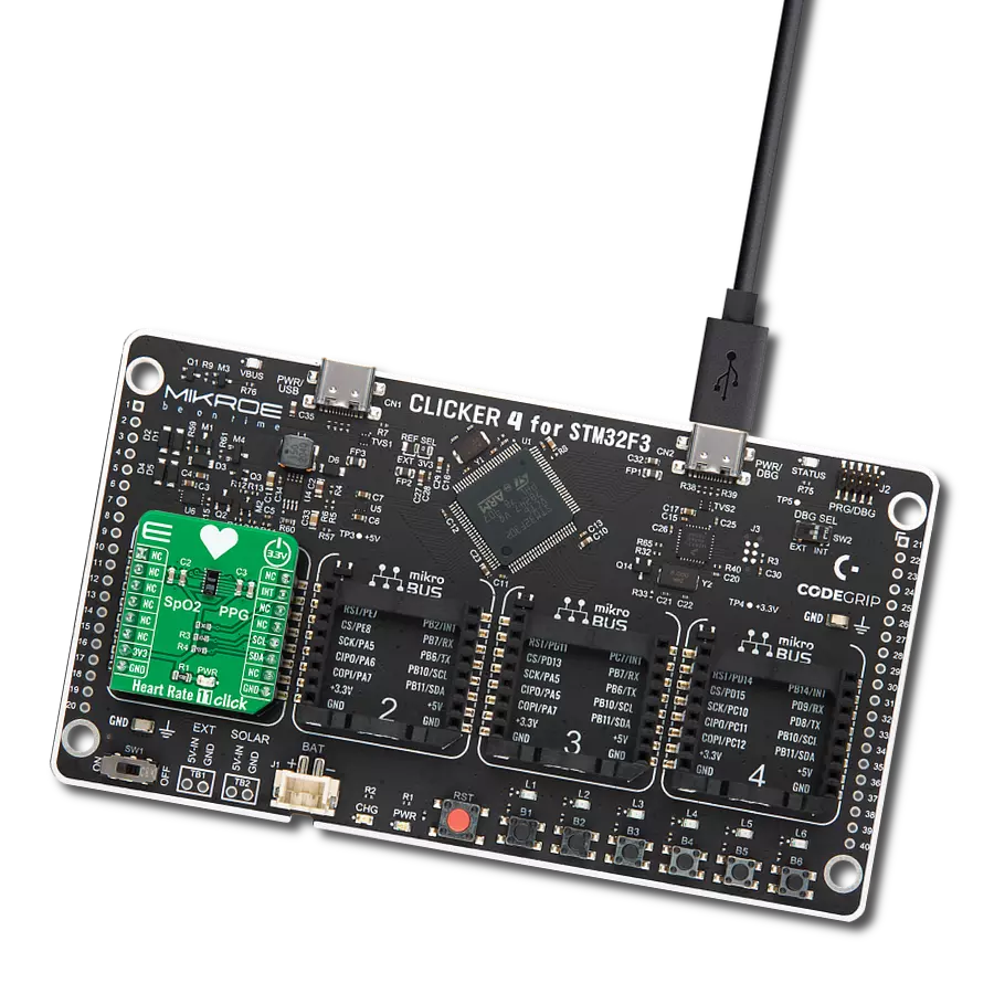
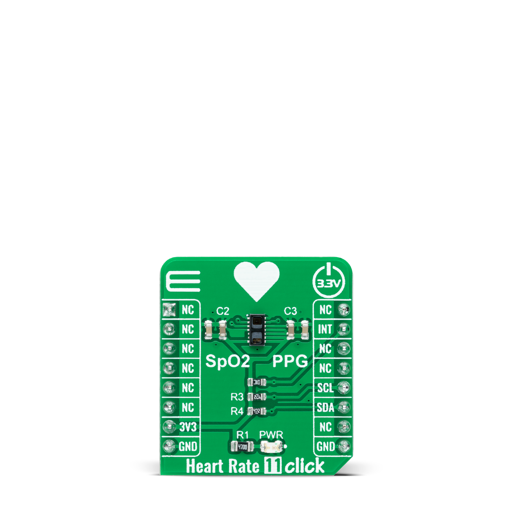
Heart Rate 11 Click
开发板
Nucleo-64 with STM32L073RZ MCU
编译器
NECTO Studio
微控制器单元
STM32L073RZ
以最简单的方式测量您的心率和血氧饱和度。
A
A
硬件概览
它是如何工作的?
Heart Rate 11 Click 基于瑞萨电子的 OB1203,这是一款集成的多合一生物传感器模块,可测量心率和血氧水平。OB1203 将所有光源、驱动器和传感器元件结合在一个光学优化的封装中。由于使用了节省空间的反射 PPG 方法,只需用户手指的一侧即可使用。适当的算法可以确定人体心率、呼吸频率和心率变异性(压力的衡量指标)或血氧饱和度(SpO2),可以在 IR 透射但可见的暗色墨水
后实现,允许在美观的工业设计中实现。生物传感器模块包含用于光(红、绿、蓝和清晰通道)、接近测量、光电容积描记法和光传感器温度补偿的不同光电二极管。这些二极管排列在矩阵阵列中,用于 PS/PPG 测量的单个二极管位于矩阵下方。光电二极管电流通过模数转换器 (ADC) 转换为数字值,然后通过串行接口转发以进行进一步处理。OB1203 使用标准 I2C 2 线接口与 MCU 通信,最大时钟频率
为 400kHz,可通过软件寄存器完全调节。此外,它使用 mikroBUS™ 插座的 INT 引脚作为中断引脚,指示何时发生特定中断事件,例如光、接近或光电容积描记法阈值被超越。此 Click board™ 只能在 3.3V 逻辑电压水平下运行。在使用不同逻辑电平的 MCU 之前,板必须执行适当的逻辑电压电平转换。然而,该 Click board™ 配备了包含函数和示例代码的库,可作为进一步开发的参考。

功能概述
开发板
Nucleo-64搭载STM32L073RZ MCU提供了一个经济实惠且灵活的平台,供开发人员探索新的想法并原型化其设计。该板利用了STM32微控制器的多功能性,使用户能够为其项目选择性能和功耗之间的最佳平衡。它采用LQFP64封装的STM32微控制器,并包括一些必要的组件,例如用户LED,可以同时作为ARDUINO®信号使用,以及用户和复位按钮,以及用于精准定时操作的32.768kHz晶体振荡器。设计时考虑了扩展性和灵活性,Nucleo-64板具有ARDUINO®
Uno V3扩展连接器和ST morpho扩展引脚标头,为全面项目集成提供了对STM32 I/O的完全访问权限。电源选项具有适应性,支持ST-LINK USB VBUS或外部电源,确保在各种开发环境中的适应性。该板还配备了一个内置的ST-LINK调试器/编程器,具有USB重新枚举功能,简化了编程和调试过程。此外,该板还设计了外部SMPS,以实现有效的Vcore逻辑供电,支持USB设备全速或USB SNK/UFP全速,以及内置的加密功能,增强了项目的功耗效率和安全性。通过专用
连接器提供了额外的连接性,用于外部SMPS实验、ST-LINK的USB连接器和MIPI®调试连接器,扩展了硬件接口和实验的可能性。开发人员将通过STM32Cube MCU软件包中全面的免费软件库和示例得到广泛的支持。这与与各种集成开发环境(IDE)的兼容性相结合,包括IAR Embedded Workbench®、MDK-ARM和STM32CubeIDE,确保了平稳高效的开发体验,使用户能够充分发挥Nucleo-64板在其项目中的功能。

微控制器概述
MCU卡片 / MCU

建筑
ARM Cortex-M0
MCU 内存 (KB)
192
硅供应商
STMicroelectronics
引脚数
64
RAM (字节)
20480
你完善了我!
配件
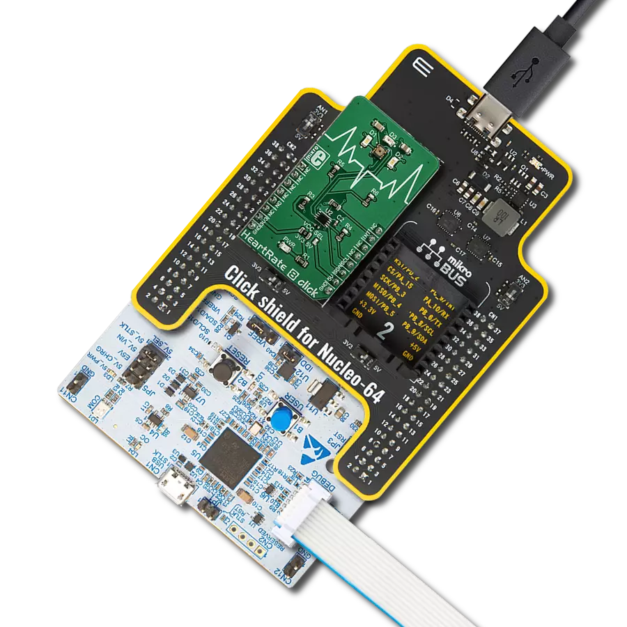
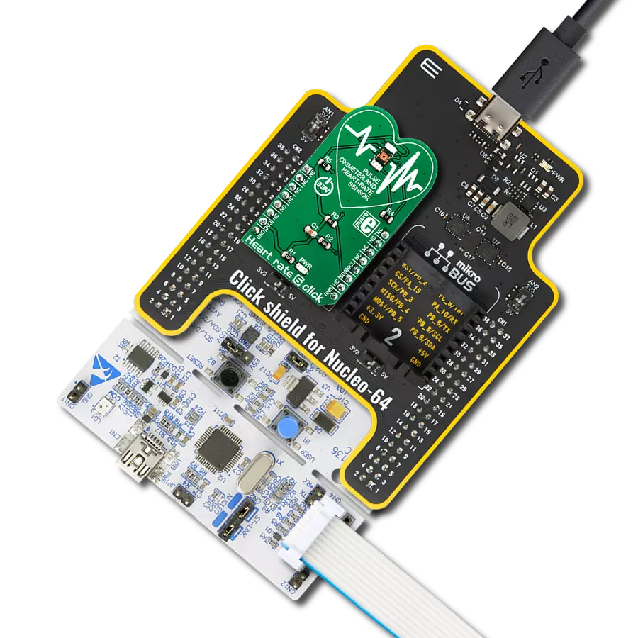
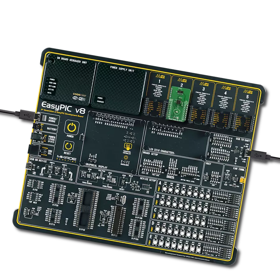
Click Shield for Nucleo-64 配备了两个专有的 mikroBUS™ 插座,使得所有的 Click board™ 设备都可以轻松地与 STM32 Nucleo-64 开发板连接。这样,Mikroe 允许其用户从不断增长的 Click boards™ 范围中添加任何功能,如 WiFi、GSM、GPS、蓝牙、ZigBee、环境传感器、LED、语音识别、电机控制、运动传感器等。您可以使用超过 1537 个 Click boards™,这些 Click boards™ 可以堆叠和集成。STM32 Nucleo-64 开发板基于 64 引脚封装的微控制器,采用 32 位 MCU,配备 ARM Cortex M4 处理器,运行速度为 84MHz,具有 512Kb Flash 和 96KB SRAM,分为两个区域,顶部区域代表 ST-Link/V2 调试器和编程器,而底部区域是一个实际的开发板。通过 USB 连接方便地控制和供电这些板子,以便直接对 Nucleo-64 开发板进行编程和高效调试,其中还需要额外的 USB 线连接到板子上的 USB 迷你接口。大多数 STM32 微控制器引脚都连接到了板子左右边缘的 IO 引脚上,然后连接到两个现有的 mikroBUS™ 插座上。该 Click Shield 还有几个开关,用于选择 mikroBUS™ 插座上模拟信号的逻辑电平和 mikroBUS™ 插座本身的逻辑电压电平。此外,用户还可以通过现有的双向电平转换器,使用任何 Click board™,无论 Click board™ 是否在 3.3V 或 5V 逻辑电压电平下运行。一旦将 STM32 Nucleo-64 开发板与我们的 Click Shield for Nucleo-64 连接,您就可以访问数百个工作于 3.3V 或 5V 逻辑电压电平的 Click boards™。

使用的MCU引脚
mikroBUS™映射器
“仔细看看!”
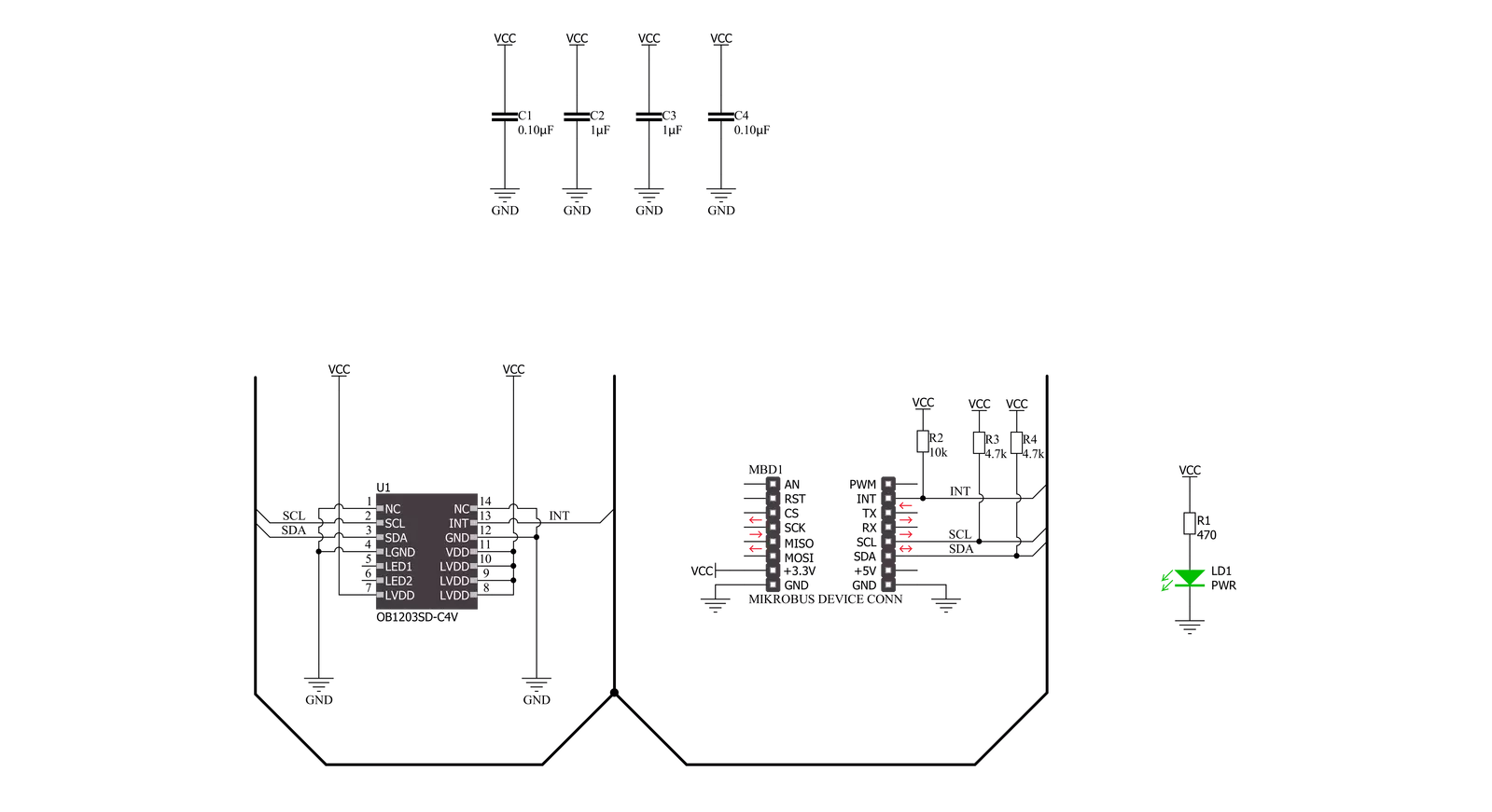
Click board™ 原理图
一步一步来
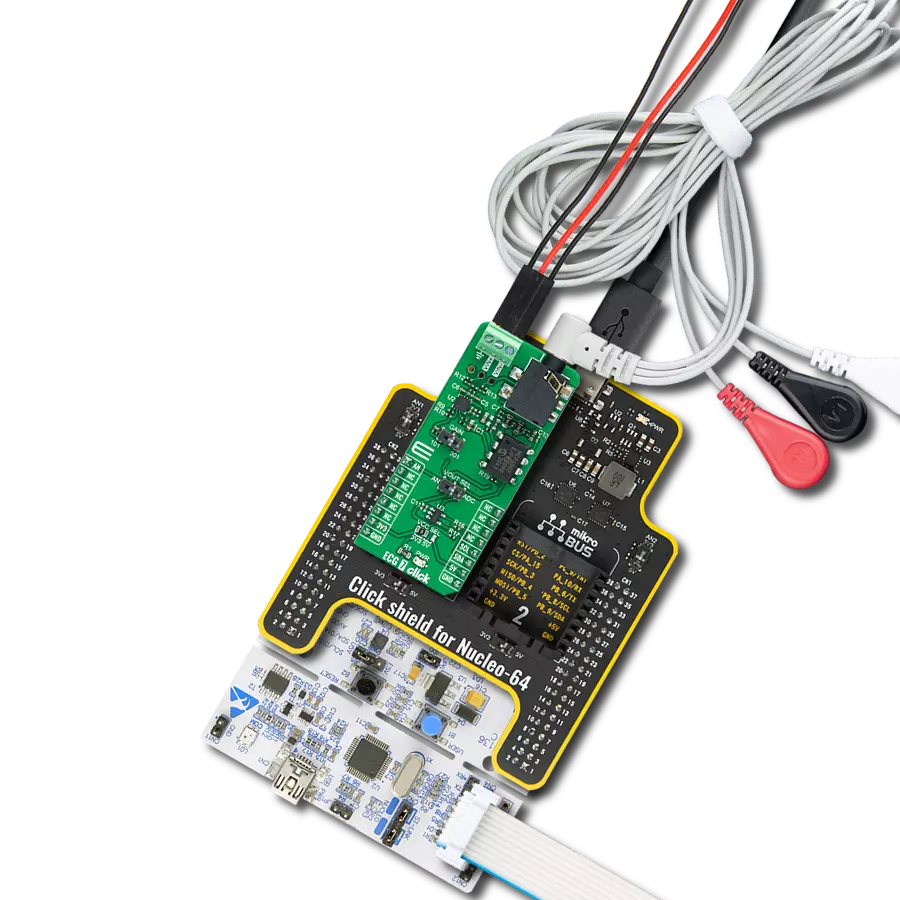
项目组装
从选择您的开发板和Click板™开始。以Nucleo-64 with STM32L073RZ MCU作为您的开发板开始。


软件支持
库描述
该库包含 Heart Rate 11 Click 驱动程序的 API。
关键功能:
heartrate11_get_int_pin- 此函数返回 INT 引脚的逻辑状态。heartrate11_set_led_current- 此函数设置所选 LED 的最大电流。heartrate11_read_fifo- 此函数从 FIFO 读取 24 位数据。
开源
代码示例
完整的应用程序代码和一个现成的项目可以通过NECTO Studio包管理器直接安装到NECTO Studio。 应用程序代码也可以在MIKROE的GitHub账户中找到。
/*!
 * @file main.c
 * @brief HeartRate11 Click example
 *
 * # Description
 * This example demonstrates the use of Heart Rate 11 Click board by reading and displaying
 * the PPG1 (HR) values which can be visualized on the SerialPlot application.
 *
 * The demo application is composed of two sections :
 *
 * ## Application Init
 * Initializes the driver and performs the Click default configuration for heart rate measurement.
 *
 * ## Application Task
 * Waits for the data ready interrupt, then reads the values of PPG from FIFO and displays it on the
 * USB UART (SerialPlot) every 32ms approximately.
 *
 * @note
 * We recommend using the SerialPlot tool for data visualizing.
 *
 * @author Stefan Filipovic
 *
 */

#include "board.h"
#include "log.h"
#include "heartrate11.h"

static heartrate11_t heartrate11;
static log_t logger;

void application_init ( void )
{
    log_cfg_t log_cfg;  /**< Logger config object. */
    heartrate11_cfg_t heartrate11_cfg;  /**< Click config object. */

    /**
     * Logger initialization.
     * Default baud rate: 115200
     * Default log level: LOG_LEVEL_DEBUG
     * @note If USB_UART_RX and USB_UART_TX
     * are defined as HAL_PIN_NC, you will
     * need to define them manually for log to work.
     * See @b LOG_MAP_USB_UART macro definition for detailed explanation.
     */
    LOG_MAP_USB_UART( log_cfg );
    log_init( &logger, &log_cfg );
    log_info( &logger, " Application Init " );

    // Click initialization.
    heartrate11_cfg_setup( &heartrate11_cfg );
    HEARTRATE11_MAP_MIKROBUS( heartrate11_cfg, MIKROBUS_1 );
    if ( I2C_MASTER_ERROR == heartrate11_init( &heartrate11, &heartrate11_cfg ) )
    {
        log_error( &logger, " Communication init." );
        for ( ; ; );
    }

    if ( HEARTRATE11_ERROR == heartrate11_default_cfg ( &heartrate11 ) )
    {
        log_error( &logger, " Default configuration." );
        for ( ; ; );
    }

    log_info( &logger, " Application Task " );
}

void application_task ( void )
{
    // Wait for the data ready interrupt indication
    while ( heartrate11_get_int_pin ( &heartrate11 ) );

    uint32_t ppg;
    if ( HEARTRATE11_OK == heartrate11_read_fifo ( &heartrate11, &ppg ) )
    {
        log_printf ( &logger, "%lu\r\n", ppg );
    }
}

int main ( void )
{
    /* Do not remove this line or clock might not be set correctly. */
    #ifdef PREINIT_SUPPORTED
    preinit();
    #endif

    application_init( );

    for ( ; ; )
    {
        application_task( );
    }

    return 0;
}

// ------------------------------------------------------------------------ END
额外支持
资源
类别:生物识别