使用TLE7259-3和STM32F103RB确保LIN总线上的可靠通信
LIN收发器:现代车辆和工业系统的无声英雄

已发布 10月 08, 2024
点击板
LIN Click
开发板
Nucleo 64 with STM32F103RB MCU
编译器
NECTO Studio
微控制器单元
STM32F103RB
信赖我们的LIN收发器,在苛刻的工业环境中进行强大的实时监控和控制,确保精度和正常运行时间。
A
A
硬件概览
它是如何工作的?
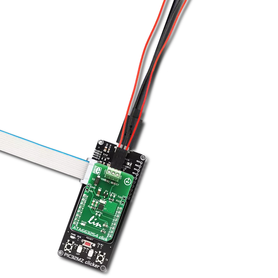
LIN Click基于Infineon Technologies的TLE7259-3,这是一款具有集成唤醒功能的LIN收发器。TLE7259-3作为协议控制器和物理LIN总线之间的总线驱动器运行,设计用于使用数据传输速率从2.4kbps到20kbps的车辆内网络。它符合所有LIN标准,并具有内置的过压和过温保护功能,以及广泛的工作供电范围,使TLE7259-3非常适用于各种汽车应用。LIN Click使用UART接口与MCU通信,默认配置下使用常用的UART RX和TX引脚以9600 bps的速率与主机MCU进行数据传输和交换。TX输入上的传输数据流会转换为具有优化斜率的LIN总线信号,而RX输出会从LIN总线读取信息到MCU。接
收器还具有集成的滤波网络,以抑制LIN总线上的噪声并增加收发器的电磁兼容性水平。该Click板提供了在主机或外设模式下工作的能力,可以通过标有MODE的板载SMD跳线器选择到适当的位置。TLE7259-3还在三种主要操作模式下运行:待机模式、正常模式和睡眠模式,由标记为EN的使能引脚的逻辑状态选择,并路由到mikroBUS™插座的CS引脚。在正常操作模式下,LIN总线接收器和LIN总线发送器是活动的,通信如常进行,而在待机模式下,LIN总线上不可能进行通信。睡眠模式显著降低了TLE7259-3的电流消耗。LIN总线还具有唤醒事件,通常称为远程唤醒,LIN总线上的下降沿后跟
着一个特定的持续时间,导致唤醒事件,将操作模式从睡眠模式更改为待机模式。除了远程唤醒,还可以通过WK引脚将TLE7259-3唤醒,该引脚路由到mikroBUS™插座的PWM引脚,称为本地唤醒。该Click板支持连接到标有VS的输入端子的外部电源,其范围应在5.5V至27V之间,适用于12V和24V板网,而LIN总线可以连接到标有BUS的端子。该Click板可以通过VCC SEL跳线选择3.3V或5V逻辑电压电平运行。这样,既支持3.3V又支持5V的MCU可以正确使用通信线路。此外,该Click板配备了一个包含易于使用的功能和示例代码的库,可作为进一步开发的参考。

功能概述
开发板
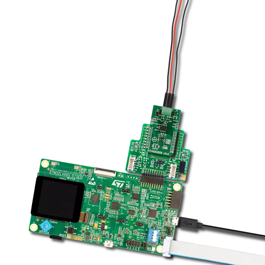
Nucleo-64 搭载 STM32F103RB MCU 提供了一种经济高效且灵活的平台,供开发者探索新想法并原型设计他们的项目。该板利用 STM32 微控制器的多功能性,使用户能够为他们的项目选择最佳的性能与功耗平衡。它配备了 LQFP64 封装的 STM32 微控制器,并包含了如用户 LED(同时作为 ARDUINO® 信号)、用户和复位按钮,以及 32.768kHz 晶体振荡器用于精确的计时操作等基本组件。Nucleo-64 板设计考虑到扩展性和灵活性,它特有的 ARDUINO® Uno
V3 扩展连接器和 ST morpho 扩展引脚头,提供了对 STM32 I/O 的完全访问,以实现全面的项目整合。电源供应选项灵活,支持 ST-LINK USB VBUS 或外部电源,确保在各种开发环境中的适应性。该板还配备了一个具有 USB 重枚举功能的板载 ST-LINK 调试器/编程器,简化了编程和调试过程。此外,该板设计旨在简化高级开发,它的外部 SMPS 为 Vcore 逻辑供电提供高效支持,支持 USB 设备全速或 USB SNK/UFP 全速,并内置加密功能,提升了项目的功效
和安全性。通过外部 SMPS 实验的专用连接器、 用于 ST-LINK 的 USB 连接器以及 MIPI® 调试连接器,提供了更多的硬件接口和实验可能性。开发者将通过 STM32Cube MCU Package 提供的全面免费软件库和示例得到广泛支持。这些,加上与多种集成开发环境(IDE)的兼容性,包括 IAR Embedded Workbench®、MDK-ARM 和 STM32CubeIDE,确保了流畅且高效的开发体验,使用户能够充分利用 Nucleo-64 板在他们的项目中的能力。

微控制器概述
MCU卡片 / MCU

建筑
ARM Cortex-M3
MCU 内存 (KB)
128
硅供应商
STMicroelectronics
引脚数
64
RAM (字节)
20480
你完善了我!
配件
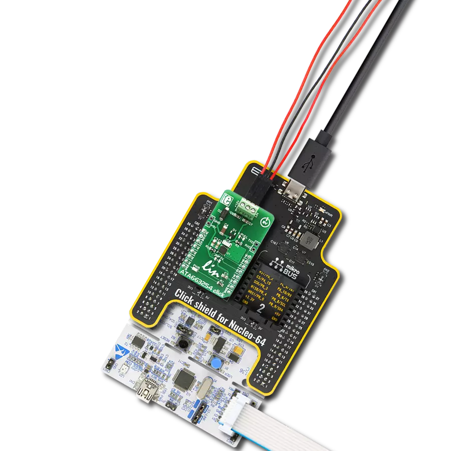
Click Shield for Nucleo-64 配备了两个专有的 mikroBUS™ 插座,使得所有的 Click board™ 设备都可以轻松地与 STM32 Nucleo-64 开发板连接。这样,Mikroe 允许其用户从不断增长的 Click boards™ 范围中添加任何功能,如 WiFi、GSM、GPS、蓝牙、ZigBee、环境传感器、LED、语音识别、电机控制、运动传感器等。您可以使用超过 1537 个 Click boards™,这些 Click boards™ 可以堆叠和集成。STM32 Nucleo-64 开发板基于 64 引脚封装的微控制器,采用 32 位 MCU,配备 ARM Cortex M4 处理器,运行速度为 84MHz,具有 512Kb Flash 和 96KB SRAM,分为两个区域,顶部区域代表 ST-Link/V2 调试器和编程器,而底部区域是一个实际的开发板。通过 USB 连接方便地控制和供电这些板子,以便直接对 Nucleo-64 开发板进行编程和高效调试,其中还需要额外的 USB 线连接到板子上的 USB 迷你接口。大多数 STM32 微控制器引脚都连接到了板子左右边缘的 IO 引脚上,然后连接到两个现有的 mikroBUS™ 插座上。该 Click Shield 还有几个开关,用于选择 mikroBUS™ 插座上模拟信号的逻辑电平和 mikroBUS™ 插座本身的逻辑电压电平。此外,用户还可以通过现有的双向电平转换器,使用任何 Click board™,无论 Click board™ 是否在 3.3V 或 5V 逻辑电压电平下运行。一旦将 STM32 Nucleo-64 开发板与我们的 Click Shield for Nucleo-64 连接,您就可以访问数百个工作于 3.3V 或 5V 逻辑电压电平的 Click boards™。

使用的MCU引脚
mikroBUS™映射器
“仔细看看!”
Click board™ 原理图

一步一步来
项目组装
从选择您的开发板和Click板™开始。以Nucleo 64 with STM32F103RB MCU作为您的开发板开始。


软件支持
库描述
此库包含LIN Click驱动程序的API。
关键功能:
lin_generic_write- 通用写入函数lin_generic_read- 通用读取函数lin_set_enable- 设置使能引脚状态
开源
代码示例
完整的应用程序代码和一个现成的项目可以通过NECTO Studio包管理器直接安装到NECTO Studio。 应用程序代码也可以在MIKROE的GitHub账户中找到。
/*!
 * \file
 * \brief Lin Click example
 *
 * # Description
 * This example reads and processes data from LIN Clicks.
 *
 * The demo application is composed of two sections :
 *
 * ## Application Init
 * Initializes the driver and makes an initial log.
 *
 * ## Application Task
 * Depending on the selected mode, it reads all the received data or sends the desired message
 * every 2 seconds.
 *
 * ## Additional Function
 * - lin_process ( ) - The general process of collecting the received data.
 *
 * @note
 * Make sure to set the onboard Master/Slave jumpers properly and to connect and power two Click
 * boards according to LIN Specification 2.2A.
 *
 * \author MikroE Team
 *
 */
// ------------------------------------------------------------------- INCLUDES

#include "board.h"
#include "log.h"
#include "lin.h"
#include "string.h"

#define PROCESS_RX_BUFFER_SIZE 500

#define TEXT_TO_SEND "MikroE - LIN Click board\r\n"

#define DEMO_APP_RECEIVER
// #define DEMO_APP_TRANSMITTER

// ------------------------------------------------------------------ VARIABLES

static lin_t lin;
static log_t logger;

// ------------------------------------------------------- ADDITIONAL FUNCTIONS

static void lin_process ( void )
{
    int32_t rsp_size;

    char uart_rx_buffer[ PROCESS_RX_BUFFER_SIZE ] = { 0 };

    rsp_size = lin_generic_read( &lin, uart_rx_buffer, PROCESS_RX_BUFFER_SIZE );

    if ( rsp_size > 0 )
    {
        for ( uint8_t cnt = 0; cnt < rsp_size; cnt++ )
        {
            log_printf( &logger, "%c", uart_rx_buffer[ cnt ] );
            if ( uart_rx_buffer[ cnt ] == '\n' )
            {
                log_printf( &logger, "---------------------------\r\n" );
            }
        }
    }
}

// ------------------------------------------------------ APPLICATION FUNCTIONS

void application_init ( void )
{
    log_cfg_t log_cfg;
    lin_cfg_t cfg;

    /**
     * Logger initialization.
     * Default baud rate: 115200
     * Default log level: LOG_LEVEL_DEBUG
     * @note If USB_UART_RX and USB_UART_TX
     * are defined as HAL_PIN_NC, you will
     * need to define them manually for log to work.
     * See @b LOG_MAP_USB_UART macro definition for detailed explanation.
     */
    LOG_MAP_USB_UART( log_cfg );
    log_init( &logger, &log_cfg );
    log_info( &logger, "---- Application Init ----" );

    //  Click initialization.

    lin_cfg_setup( &cfg );
    LIN_MAP_MIKROBUS( cfg, MIKROBUS_1 );
    lin_init( &lin, &cfg );
    Delay_ms ( 100 );

    lin_set_enable ( &lin, 1 );
    lin_set_wake_up ( &lin, 0 );
    Delay_ms ( 100 );
#ifdef DEMO_APP_RECEIVER
    log_info( &logger, "---- Receiver mode ----" );
#endif
#ifdef DEMO_APP_TRANSMITTER
    log_info( &logger, "---- Transmitter mode ----" );
#endif
}

void application_task ( void )
{
#ifdef DEMO_APP_RECEIVER
    lin_process( );
#endif

#ifdef DEMO_APP_TRANSMITTER
    lin_generic_write( &lin, TEXT_TO_SEND, strlen( TEXT_TO_SEND ) );
    log_info( &logger, "---- Data sent ----" );
    Delay_ms ( 1000 );
    Delay_ms ( 1000 );
#endif
}

int main ( void )
{
    /* Do not remove this line or clock might not be set correctly. */
    #ifdef PREINIT_SUPPORTED
    preinit();
    #endif

    application_init( );

    for ( ; ; )
    {
        application_task( );
    }

    return 0;
}

// ------------------------------------------------------------------------ END
额外支持
资源
类别:局部互连网络