使用BC95-G和STM32F446RE将您的物联网愿景变为现实
通过多频段NB技术提升效率

已发布 10月 08, 2024
点击板
NB IoT Click
开发板
Nucleo 64 with STM32F446RE MCU
编译器
NECTO Studio
微控制器单元
STM32F446RE
重新定义连接性,无缝连接设备,在您的物联网项目中实现新的控制和效率水平。
A
A
硬件概览
它是如何工作的?
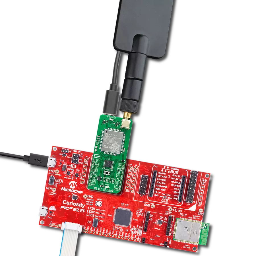
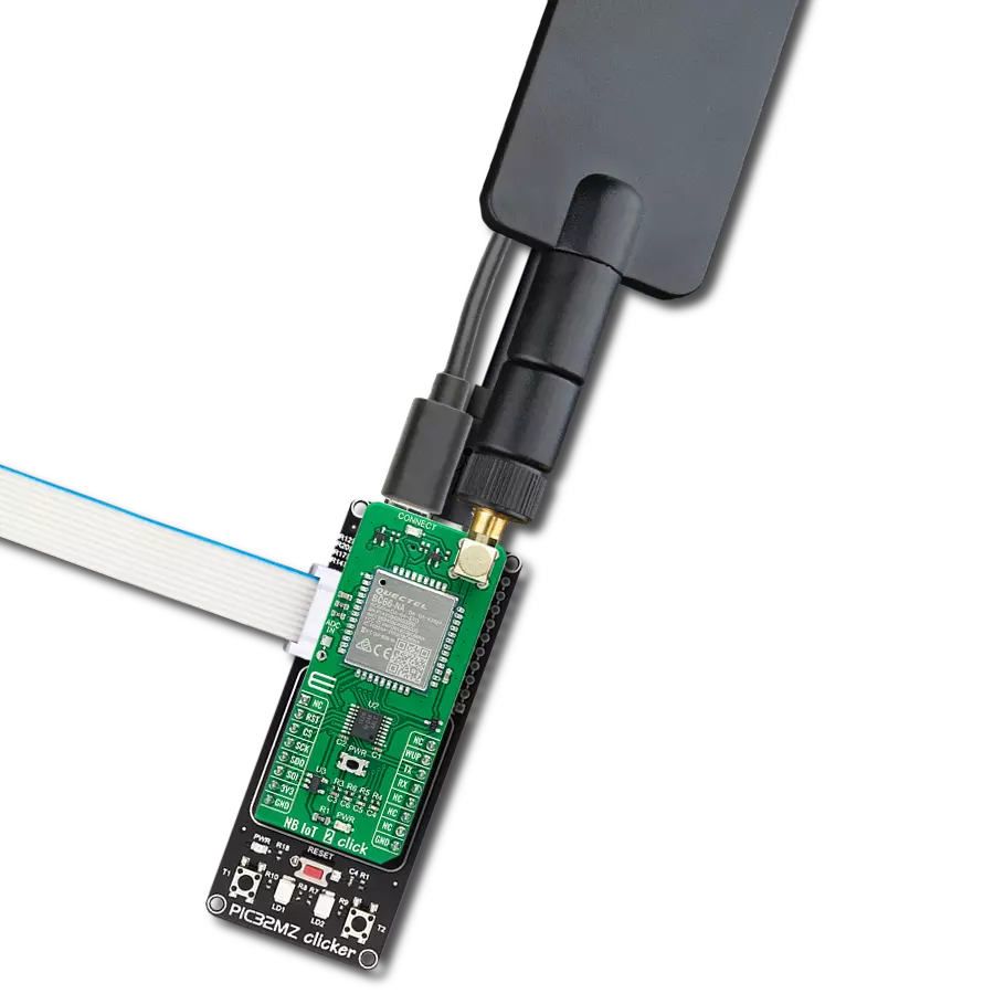
NB IoT Click 基于 Quectel Wireless Solutions 的 BC95-G 模块,支持专为物联网应用开发的 LTE NB1 技术。它支持多个 NB 频段:B1、B3、B5、B8、B20 和 B28。该模块支持点对点的 MO 和 MT 消息,广泛用于 M2M 通信。其包含的协议集允许使用 NB1 技术进行数据和短信传输,并且具有超低功耗,使其成为构建物联网应用的理想选择。正如前面提到的,BC95-G 模块是 Click 板的主要组件,由多个内部块或部分组成,如 RF 收发器部分、Flash SRAM 部分、电源管理部分以及具有外围接口的蜂窝基带处理器。BC95 模块支持多个外围接口,包括两个 UART 接口(包括主 UART 和调试 UART 接口)、USIM 卡接口和 GPIO 接口。主 UART 接口可用于 AT 命令通信和数据传输,支持 9600 bps 的波特率。在固件升级时使用 115200 bps 的波特率。Quectel BC95 模块必须由干净稳定的电源供电。模块正常工作所需的电压为 4V,通过 MCP1826 从 5V mikroBUS™ 电源轨导出,MCP1826 是 Microchip 的 1A 低压降输出 (LDO) 稳压器。
尽管 Quectel BC95 模块是超低功耗设备,但其功耗有时会短暂峰值,因此需要使用 1A LDO。BC95 模块没有专用的 USB 接口,因此在 NB IoT Click 上添加了 USB 到 UART 电路,以提供 USB 到 UART 转换。使用了 FTDI 的 FT230X,这是一种高度集成的 USB-UART 桥接解决方案,具有紧凑的尺寸和所需的外部组件少的优点。两颗 LED 用于指示通过该 IC 的数据流量:标记为 TX 的红色 LED 表示 UART 传输,而标记为 RX 的黄色 LED 表示 UART 接收。该 Click 板配备了 micro USB 连接器,允许模块通过个人电脑供电和配置。Quectel Wireless Solutions 公司提供了一个软件套件,可以用于配置 BC95 模块。然而,FT230X IC 需要驱动程序才能工作。FTDI 提供了所有主要操作系统的驱动程序,具体可在其官方网站的驱动程序下载页面找到。Windows 操作系统的驱动程序也包含在下载部分。Click 板背面的 micro SIM 卡座用于安装 SIM 卡。没有有效的 SIM 卡,设备无法连接到蜂窝网络。BC95 模块的数字部分由集成的 LDO 稳压器供电,因此有必要
转换微控制器 (MCU) 通信线的逻辑电压电平。通过利用 LDO 输出(通过 MOSFET 开关电路路由),为 TXB0106 的一侧提供所需的参考电压,这是一种 6 位双向逻辑电压电平转换器。TXB0106 另一侧的参考电压取自 mikroBUS™ 的 3.3V 电源轨。一些信号级 MOSFET 组成的小型开关电路用于在 Click 板插入 mikroBUS™ 插座时关闭 FT230X,从而允许与主 MCU 的不间断通信。STAT 引脚用于指示设备状态。该引脚通过 TXB0106 电平转换器连接到 mikroBUS™ AN 引脚,并连接到标记为 STAT 的黄色 LED,用于直观地指示设备状态。通过将 mikroBUS™ 引脚的 RST 引脚拉到低电平,可以重置模块。该引脚通过内部上拉电阻上拉到高电平。除了硬件复位外,还可以使用 AT 命令复位模块。有关可用 AT 命令的更多信息,请参阅下载部分。然而,Click 板由 mikroSDK 库支持。该库包含简化软件开发的函数,将多个 AT 命令集成到单个函数调用中。使用 mikroSDK 使代码更加可读,但更重要的是,易于移植。

功能概述
开发板
Nucleo-64 搭载 STM32F446RE MCU 提供了一种经济高效且灵活的平台,供开发者探索新想法并原型设计他们的项目。该板利用 STM32 微控制器的多功能性,使用户能够为他们的项目选择最佳的性能与功耗平衡。它配备了 LQFP64 封装的 STM32 微控制器,并包含了如用户 LED(同时作为 ARDUINO® 信号)、用户和复位按钮,以及 32.768kHz 晶体振荡器用于精确的计时操作等基本组件。Nucleo-64 板设计考虑到扩展性和灵活性,它特有的 ARDUINO® Uno
V3 扩展连接器和 ST morpho 扩展引脚头,提供了对 STM32 I/O 的完全访问,以实现全面的项目整合。电源供应选项灵活,支持 ST-LINK USB VBUS 或外部电源,确保在各种开发环境中的适应性。该板还配备了一个具有 USB 重枚举功能的板载 ST-LINK 调试器/编程器,简化了编程和调试过程。此外,该板设计旨在简化高级开发,它的外部 SMPS 为 Vcore 逻辑供电提供高效支持,支持 USB 设备全速或 USB SNK/UFP 全速,并内置加密功能,提升了项目的功效
和安全性。通过外部 SMPS 实验的专用连接器、 用于 ST-LINK 的 USB 连接器以及 MIPI® 调试连接器,提供了更多的硬件接口和实验可能性。开发者将通过 STM32Cube MCU Package 提供的全面免费软件库和示例得到广泛支持。这些,加上与多种集成开发环境(IDE)的兼容性,包括 IAR Embedded Workbench®、MDK-ARM 和 STM32CubeIDE,确保了流畅且高效的开发体验,使用户能够充分利用 Nucleo-64 板在他们的项目中的能力。

微控制器概述
MCU卡片 / MCU

建筑
ARM Cortex-M4
MCU 内存 (KB)
512
硅供应商
STMicroelectronics
引脚数
64
RAM (字节)
131072
你完善了我!
配件
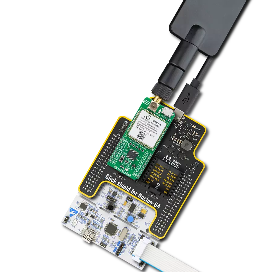
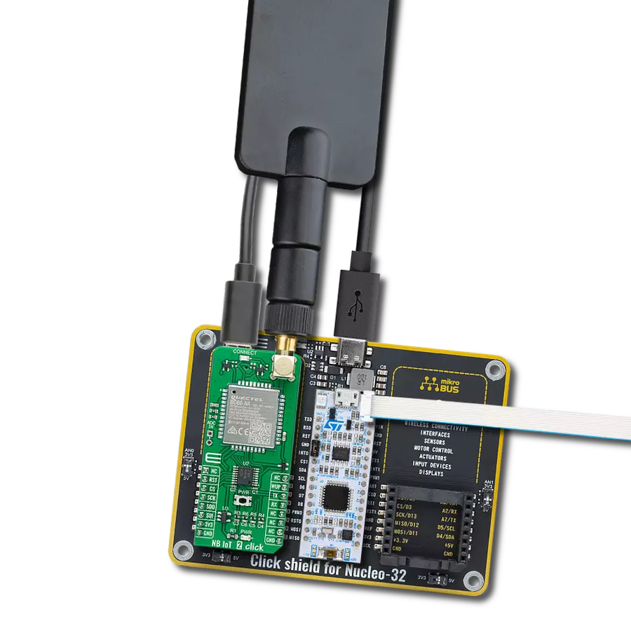
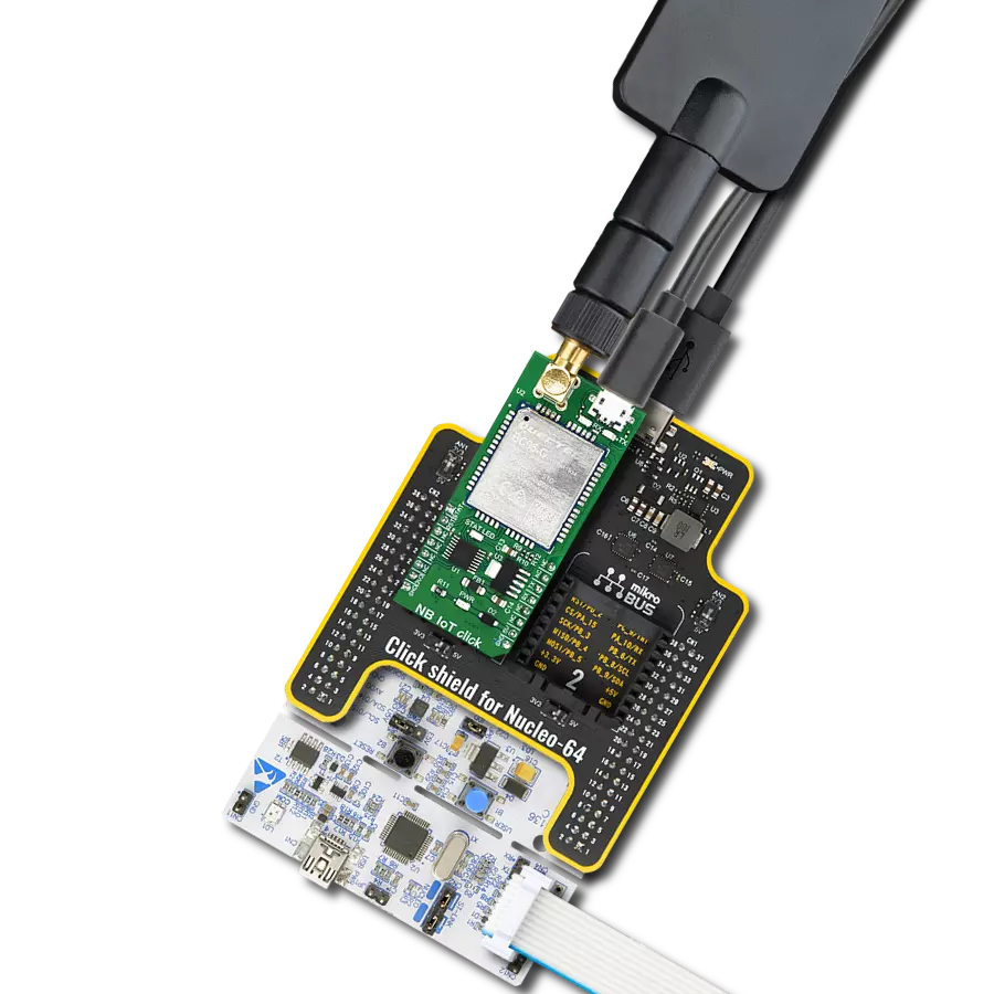
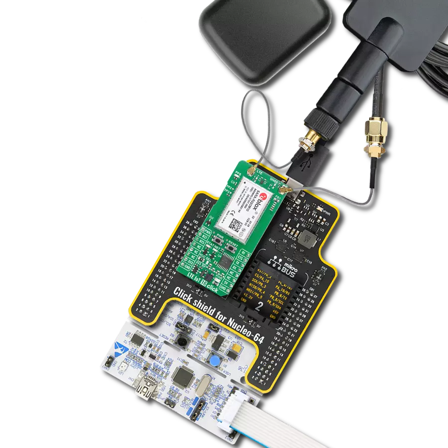
Click Shield for Nucleo-64 配备了两个专有的 mikroBUS™ 插座,使得所有的 Click board™ 设备都可以轻松地与 STM32 Nucleo-64 开发板连接。这样,Mikroe 允许其用户从不断增长的 Click boards™ 范围中添加任何功能,如 WiFi、GSM、GPS、蓝牙、ZigBee、环境传感器、LED、语音识别、电机控制、运动传感器等。您可以使用超过 1537 个 Click boards™,这些 Click boards™ 可以堆叠和集成。STM32 Nucleo-64 开发板基于 64 引脚封装的微控制器,采用 32 位 MCU,配备 ARM Cortex M4 处理器,运行速度为 84MHz,具有 512Kb Flash 和 96KB SRAM,分为两个区域,顶部区域代表 ST-Link/V2 调试器和编程器,而底部区域是一个实际的开发板。通过 USB 连接方便地控制和供电这些板子,以便直接对 Nucleo-64 开发板进行编程和高效调试,其中还需要额外的 USB 线连接到板子上的 USB 迷你接口。大多数 STM32 微控制器引脚都连接到了板子左右边缘的 IO 引脚上,然后连接到两个现有的 mikroBUS™ 插座上。该 Click Shield 还有几个开关,用于选择 mikroBUS™ 插座上模拟信号的逻辑电平和 mikroBUS™ 插座本身的逻辑电压电平。此外,用户还可以通过现有的双向电平转换器,使用任何 Click board™,无论 Click board™ 是否在 3.3V 或 5V 逻辑电压电平下运行。一旦将 STM32 Nucleo-64 开发板与我们的 Click Shield for Nucleo-64 连接,您就可以访问数百个工作于 3.3V 或 5V 逻辑电压电平的 Click boards™。

LTE 平板旋转天线是提高 3G/4G LTE 设备性能的多功能选择。其宽频率范围为 700-2700MHz,确保在全球主要蜂窝频段上的最佳连接性。这款平板天线配有 SMA 公头连接器,可轻松直接连接到您的设备或 SMA 模块连接器。其突出特点之一是可调角度,可以以 45⁰ 为增量进行设置(0⁰/45⁰/90⁰),允许您微调天线的方向以实现最佳信号接收。该天线具有 50Ω 的阻抗和 <2.0:1 的电压驻波比 (VSW 比),确保可靠且高效的连接。其 5dB 增益、垂直极化和全向辐射图形增强了信号强度,适用于各种应用。天线长度为 196mm,宽度为 38mm,提供紧凑而有效的解决方案,以改善您的连接性。其最大输入功率为 50W,能够满足各种设备的需求。

使用的MCU引脚
mikroBUS™映射器
“仔细看看!”
Click board™ 原理图

一步一步来
项目组装
从选择您的开发板和Click板™开始。以Nucleo 64 with STM32F446RE MCU作为您的开发板开始。


实时跟踪您的结果
应用程序输出
1. 应用程序输出 - 在调试模式下,“应用程序输出”窗口支持实时数据监控,直接提供执行结果的可视化。请按照提供的教程正确配置环境,以确保数据正确显示。

2. UART 终端 - 使用UART Terminal通过USB to UART converter监视数据传输,实现Click board™与开发系统之间的直接通信。请根据项目需求配置波特率和其他串行设置,以确保正常运行。有关分步设置说明,请参考提供的教程。

3. Plot 输出 - Plot功能提供了一种强大的方式来可视化实时传感器数据,使趋势分析、调试和多个数据点的对比变得更加直观。要正确设置,请按照提供的教程,其中包含使用Plot功能显示Click board™读数的分步示例。在代码中使用Plot功能时,请使用以下函数:plot(insert_graph_name, variable_name);。这是一个通用格式,用户需要将“insert_graph_name”替换为实际图表名称,并将“variable_name”替换为要显示的参数。

软件支持
库描述
该库包含 NB IoT Click 驱动程序的 API。
关键功能:
nbiot_send_cmd- 发送命令函数nbiot_power_on- NB IoT 模块上电nbiot_generic_write- NB IoT 数据写入函数
开源
代码示例
完整的应用程序代码和一个现成的项目可以通过NECTO Studio包管理器直接安装到NECTO Studio。 应用程序代码也可以在MIKROE的GitHub账户中找到。
/*!
 * \file
 * \brief NbIot Click example
 *
* # Description
 * This example reads and processes data from NB IoT Clicks.
 *
 * The demo application is composed of two sections :
 *
 * ## Application Init
 * Initializes driver, wake-up module and sets default configuration
 * for connecting device to network.
 *
 * ## Application Task
 * Waits for device to connect to network and then checks the signal quality
 * every 5 seconds. All data is being logged on USB UART where you can track their changes.
 *
 * ## Additional Function
 * - static void nbiot_clear_app_buf ( void )
 * - static void nbiot_error_check( err_t error_flag )
 * - static void nbiot_log_app_buf ( void )
 * - static void nbiot_check_connection( void )
 * - static err_t nbiot_rsp_check ( void )
 * - static err_t nbiot_process ( void )
 *
 * @note
 * In order for the example to work, a valid SIM card needs to be entered.
 *
 * @author MikroE Team
 *
 */
// ------------------------------------------------------------------- INCLUDES

#include "board.h"
#include "log.h"
#include "nbiot.h"

#define APP_OK                              0
#define APP_ERROR_DRIVER                    -1
#define APP_ERROR_OVERFLOW                  -2
#define APP_ERROR_TIMEOUT                   -3

#define RSP_OK                              "OK"
#define RSP_ERROR                           "ERROR"

#define PROCESS_BUFFER_SIZE                 500

#define WAIT_FOR_CONNECTION                 0
#define CONNECTED_TO_NETWORK                1

static nbiot_t nbiot;
static log_t logger;

static char app_buf[ PROCESS_BUFFER_SIZE ]  = { 0 };
static int32_t app_buf_len                  = 0;
static int32_t app_buf_cnt                  = 0;

static uint8_t app_connection_status        = WAIT_FOR_CONNECTION;

static err_t app_error_flag;

/**
 * @brief NB IoT clearing application buffer.
 * @details This function clears memory of application buffer and reset its length and counter.
 * @note None.
 */
static void nbiot_clear_app_buf ( void );

/**
 * @brief NB IoT data reading function.
 * @details This function reads data from device and concats data to application buffer.
 *
 * @return @li @c  0 - Read some data.
 *         @li @c -1 - Nothing is read.
 *         @li @c -2 - Application buffer overflow.
 *
 * See #err_t definition for detailed explanation.
 * @note None.
 */
static err_t nbiot_process ( void );

/**
 * @brief NB IoT check for errors.
 * @details This function checks for different types of errors and logs them on UART.
 * @note None.
 */
static void nbiot_error_check( err_t error_flag );

/**
 * @brief NB IoT logs application buffer.
 * @details This function logs data from application buffer.
 * @note None.
 */
static void nbiot_log_app_buf ( void );

/**
 * @brief NB IoT response check.
 * @details This function checks for response and returns the status of response.
 *
 * @return application status.
 * See #err_t definition for detailed explanation.
 * @note None.
 */
static err_t nbiot_rsp_check ( void );

/**
 * @brief NB IoT chek connection.
 * @details This function checks connection to the network and
 *          logs that status to UART.
 *
 * @note None.
 */
static void nbiot_check_connection( void );

// ------------------------------------------------------ APPLICATION FUNCTIONS

void application_init ( void )
{
    log_cfg_t log_cfg;  /**< Logger config object. */
    nbiot_cfg_t nbiot_cfg;  /**< Click config object. */

    /**
     * Logger initialization.
     * Default baud rate: 115200
     * Default log level: LOG_LEVEL_DEBUG
     * @note If USB_UART_RX and USB_UART_TX
     * are defined as HAL_PIN_NC, you will
     * need to define them manually for log to work.
     * See @b LOG_MAP_USB_UART macro definition for detailed explanation.
     */
    LOG_MAP_USB_UART( log_cfg );
    log_init( &logger, &log_cfg );
    log_info( &logger, " Application Init " );
    Delay_ms ( 1000 );

    // Click initialization.
    nbiot_cfg_setup( &nbiot_cfg );
    NBIOT_MAP_MIKROBUS( nbiot_cfg, MIKROBUS_1 );
    err_t init_flag  = nbiot_init( &nbiot, &nbiot_cfg );
    if ( init_flag == UART_ERROR )
    {
        log_error( &logger, " Application Init Error. " );
        log_info( &logger, " Please, run program again... " );

        for ( ; ; );
    }

    log_info( &logger, " Power on device... " );
    nbiot_power_on( &nbiot );
    // dummy read
    app_error_flag = nbiot_rsp_check(  );
    nbiot_error_check( app_error_flag );

    // AT
    nbiot_send_cmd( &nbiot, NBIOT_CMD_AT );
    app_error_flag = nbiot_rsp_check( );
    nbiot_error_check( app_error_flag );
    Delay_ms ( 500 );

    // ATI - product information
    nbiot_send_cmd( &nbiot, NBIOT_CMD_ATI );
    app_error_flag = nbiot_rsp_check(  );
    nbiot_error_check( app_error_flag );
    Delay_ms ( 500 );

    // CGMR - firmware version
    nbiot_send_cmd( &nbiot, NBIOT_CMD_CGMR );
    app_error_flag = nbiot_rsp_check(  );
    nbiot_error_check( app_error_flag );
    Delay_ms ( 1000 );

    // COPS - deregister from network
    nbiot_send_cmd_with_parameter( &nbiot, NBIOT_CMD_COPS, "2" );
    app_error_flag = nbiot_rsp_check(  );
    nbiot_error_check( app_error_flag );
    Delay_ms ( 1000 );

    // CFUN - full funtionality
    nbiot_send_cmd_with_parameter( &nbiot, NBIOT_CMD_CFUN, "1" );
    app_error_flag = nbiot_rsp_check(  );
    nbiot_error_check( app_error_flag );
    Delay_ms ( 500 );

    // COPS - automatic mode
    nbiot_send_cmd_with_parameter( &nbiot, NBIOT_CMD_COPS, "0" );
    app_error_flag = nbiot_rsp_check(  );
    nbiot_error_check( app_error_flag );
    Delay_ms ( 1000 );
    Delay_ms ( 1000 );

    // CEREG - network registration status
    nbiot_send_cmd_with_parameter( &nbiot, NBIOT_CMD_CEREG, "2" );
    app_error_flag = nbiot_rsp_check(  );
    nbiot_error_check( app_error_flag );
    Delay_ms ( 500 );

    // CIMI - request IMSI
    nbiot_send_cmd( &nbiot, NBIOT_CMD_CIMI );
    app_error_flag = nbiot_rsp_check(  );
    nbiot_error_check( app_error_flag );
    Delay_ms ( 500 );

    app_buf_len = 0;
    app_buf_cnt = 0;
    app_connection_status = WAIT_FOR_CONNECTION;
    log_info( &logger, " Application Task " );
    Delay_ms ( 1000 );
    Delay_ms ( 1000 );
    Delay_ms ( 1000 );
    Delay_ms ( 1000 );
    Delay_ms ( 1000 );
}

void application_task ( void )
{
    if ( app_connection_status == WAIT_FOR_CONNECTION )
    {
        // CGATT - request IMSI
        nbiot_send_cmd_check( &nbiot, NBIOT_CMD_CGATT );
        app_error_flag = nbiot_rsp_check(  );
        nbiot_error_check( app_error_flag );
        Delay_ms ( 500 );

        // CEREG - network registration status
        nbiot_send_cmd_check( &nbiot, NBIOT_CMD_CEREG );
        app_error_flag = nbiot_rsp_check(  );
        nbiot_error_check( app_error_flag );
        Delay_ms ( 500 );

        // CSQ - signal quality
        nbiot_send_cmd( &nbiot, NBIOT_CMD_CSQ );
        app_error_flag = nbiot_rsp_check(  );
        nbiot_error_check( app_error_flag );
        Delay_ms ( 1000 );
        Delay_ms ( 1000 );
        Delay_ms ( 1000 );
        Delay_ms ( 1000 );
        Delay_ms ( 1000 );
    }
    else
    {
        log_info( &logger, "CONNECTED TO NETWORK" );

        log_info( &logger, "CHECKING SIGNAL QUALITY" );
        nbiot_send_cmd( &nbiot, NBIOT_CMD_CSQ );
        app_error_flag = nbiot_rsp_check(  );
        nbiot_error_check( app_error_flag );
        Delay_ms ( 1000 );
        Delay_ms ( 1000 );
        Delay_ms ( 1000 );
        Delay_ms ( 1000 );
        Delay_ms ( 1000 );
    }
}

int main ( void )
{
    /* Do not remove this line or clock might not be set correctly. */
    #ifdef PREINIT_SUPPORTED
    preinit();
    #endif

    application_init( );

    for ( ; ; )
    {
        application_task( );
    }

    return 0;
}

static void nbiot_clear_app_buf ( void )
{
    memset( app_buf, 0, app_buf_len );
    app_buf_len = 0;
    app_buf_cnt = 0;
}

static err_t nbiot_process ( void )
{
    err_t return_flag = APP_ERROR_DRIVER;
    int32_t rx_size;
    char rx_buff[ PROCESS_BUFFER_SIZE ] = { 0 };

    rx_size = nbiot_generic_read( &nbiot, rx_buff, PROCESS_BUFFER_SIZE );

    if ( rx_size > 0 )
    {
        int32_t buf_cnt = 0;
        return_flag = APP_OK;

        if ( app_buf_len + rx_size >= PROCESS_BUFFER_SIZE )
        {
            nbiot_clear_app_buf(  );
            return_flag = APP_ERROR_OVERFLOW;
        }
        else
        {
            buf_cnt = app_buf_len;
            app_buf_len += rx_size;
        }

        for ( int32_t rx_cnt = 0; rx_cnt < rx_size; rx_cnt++ )
        {
            if ( rx_buff[ rx_cnt ] != 0 )
            {
                app_buf[ ( buf_cnt + rx_cnt ) ] = rx_buff[ rx_cnt ];
            }
            else
            {
                app_buf_len--;
                buf_cnt--;
            }
        }
    }

    return return_flag;
}

static err_t nbiot_rsp_check ( void )
{
    uint16_t timeout_cnt = 0;
    uint16_t timeout = 20000;

    err_t error_flag = nbiot_process(  );

    if ( ( error_flag != 0 ) && ( error_flag != -1 ) )
    {
        return error_flag;
    }

    while ( ( strstr( app_buf, RSP_OK ) == 0 ) && ( strstr( app_buf, RSP_ERROR ) == 0 ) )
    {
        error_flag = nbiot_process(  );
        if ( ( error_flag != 0 ) && ( error_flag != -1 ) )
        {
            return error_flag;
        }

        timeout_cnt++;
        if ( timeout_cnt > timeout )
        {
            while ( ( strstr( app_buf, RSP_OK ) == 0 ) && ( strstr( app_buf, RSP_ERROR ) == 0 ) )
            {
                nbiot_send_cmd( &nbiot, NBIOT_CMD_AT );
                nbiot_process(  );
                Delay_ms ( 100 );
            }
            nbiot_clear_app_buf(  );
            return APP_ERROR_TIMEOUT;
        }

        Delay_ms ( 1 );
    }

    nbiot_check_connection();

    nbiot_log_app_buf();

    log_printf( &logger, "-----------------------------------\r\n" );

    return APP_OK;
}

static void nbiot_error_check( err_t error_flag )
{
    if ( ( error_flag != 0 ) && ( error_flag != -1 ) )
    {
        switch ( error_flag )
        {
            case -2:
                log_error( &logger, " Overflow!" );
                break;
            case -3:
                log_error( &logger, " Timeout!" );
                break;
            default:
                break;
        }
    }
}

static void nbiot_log_app_buf ( void )
{
    for ( int32_t buf_cnt = 0; buf_cnt < app_buf_len; buf_cnt++ )
    {
        log_printf( &logger, "%c", app_buf[ buf_cnt ] );
    }
    log_printf( &logger, "\r\n" );
    nbiot_clear_app_buf(  );
}

static void nbiot_check_connection( void )
{
    #define CONNECTED "+CGATT:1"

    if ( strstr( app_buf, CONNECTED ) != 0 )
    {
        app_connection_status = CONNECTED_TO_NETWORK;
    }
}

// ------------------------------------------------------------------------ END
额外支持
资源
类别:LTE 物联网