使用1312121320437和STM32F031K6创建视觉上吸引人的互动灯光显示
2x4 RGB LED矩阵,用于动态和彩色的灯光效果

已发布 10月 08, 2024
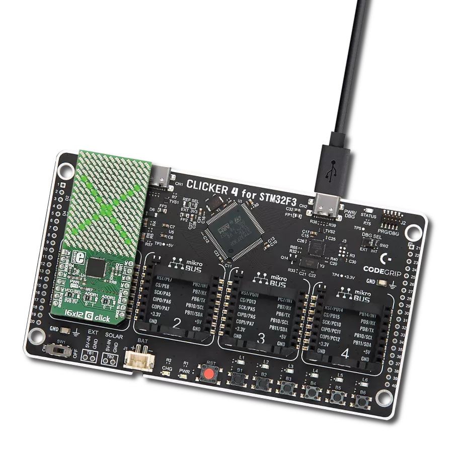
点击板
2x4 RGB Click
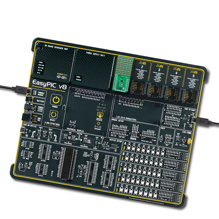
开发板
Nucleo 32 with STM32F031K6 MCU
编译器
NECTO Studio
微控制器单元
STM32F031K6
为信息展示或广告提供动态且引人注目的视觉显示
A
A
硬件概览
它是如何工作的?
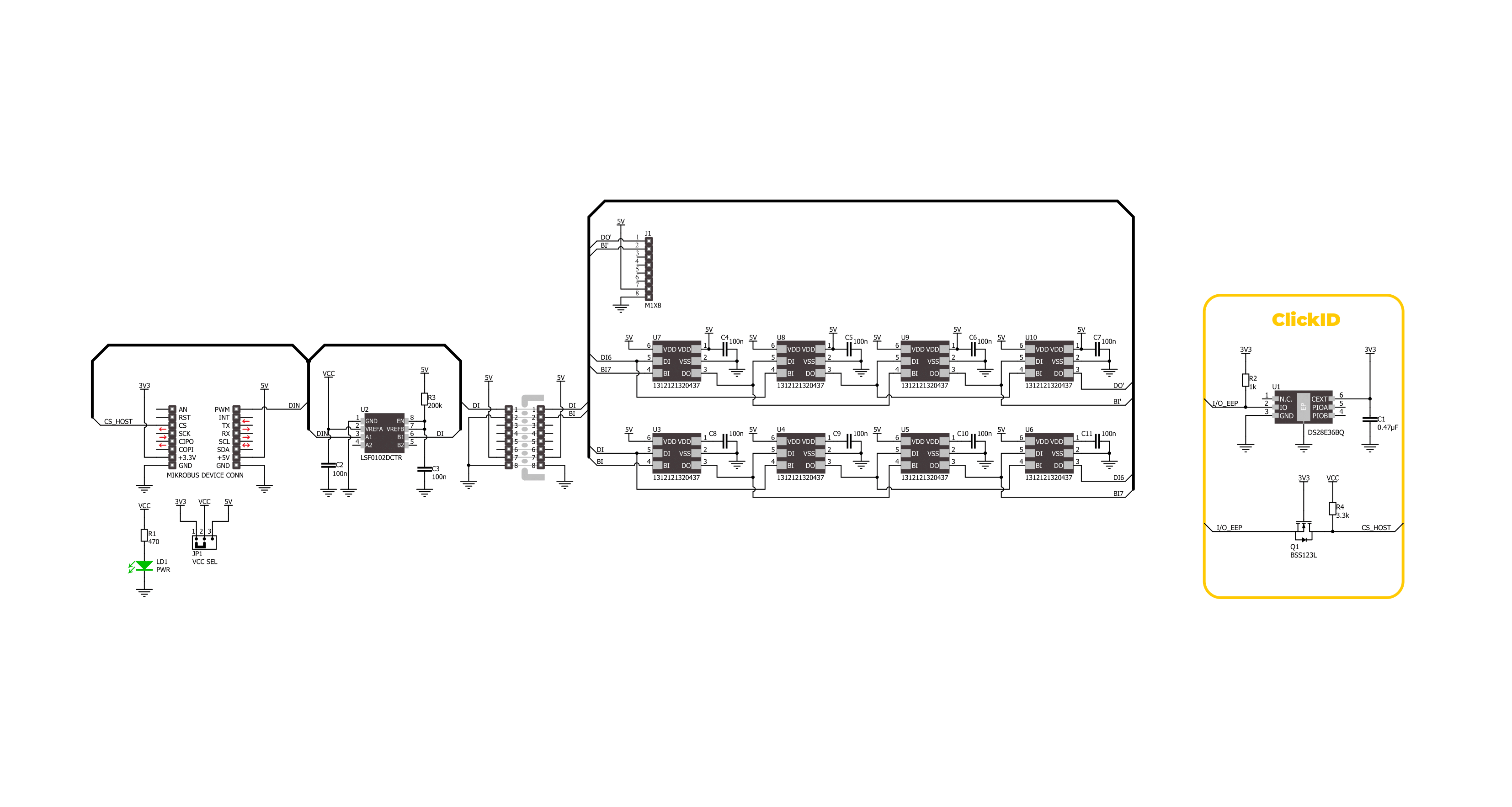
2x4 RGB Click基于来自Würth Elektronik的2x4 RGB LED阵列(WL-ICLED 1312121320437),专为动态和色彩丰富的照明应用而设计。这些LED集成了一个IC(常称为可寻址或智能LED),通过脉宽调制(PWM)实现对每个二极管的红、绿、蓝组件的单独控制,从而实现精确的颜色混合,提供广泛的色彩输出。为确保与3.3V和5V逻辑系统兼容,该Click板™配备了LSF0102电压转换器,无缝控制LED,无论MCU
的逻辑电平如何,确保在各种系统配置中的可靠性能。2x4 RGB Click采用了独特的设计,支持MIKROE新推出的“Click Snap”功能。与标准版Click板不同,此功能允许通过断开PCB使主IC区域变为可移动状态,开辟了许多新的实现可能性。得益于Snap功能,1312121320437可以通过直接访问标记为1-8的引脚自主运行。此外,Snap部分还包含指定和固定的螺钉孔位置,允许用户将Snap板固定在所需位置,并在顶
部配备未焊接的J1接头,允许串联多个Snap单元进行控制。此Click板™可以通过VCC SEL跳线选择在3.3V或5V逻辑电压下运行。这样,支持3.3V和5V逻辑电平的MCU都可以正确使用通信线路。此外,该Click板™还配备了包含易于使用的函数和示例代码的库,可作为进一步开发的参考。

功能概述
开发板
Nucleo 32开发板搭载STM32F031K6 MCU,提供了一种经济且灵活的平台,适用于使用32引脚封装的STM32微控制器进行实验。该开发板具有Arduino™ Nano连接性,便于通过专用扩展板进行功能扩展,并且支持mbed,使其能够无缝集成在线资源。板载集成
ST-LINK/V2-1调试器/编程器,支持通过USB重新枚举,提供三种接口:虚拟串口(Virtual Com port)、大容量存储和调试端口。该开发板的电源供应灵活,可通过USB VBUS或外部电源供电。此外,还配备了三个LED指示灯(LD1用于USB通信,LD2用于电源
指示,LD3为用户可控LED)和一个复位按钮。STM32 Nucleo-32开发板支持多种集成开发环境(IDEs),如IAR™、Keil®和基于GCC的IDE(如AC6 SW4STM32),使其成为开发人员的多功能工具。

微控制器概述
MCU卡片 / MCU

建筑
ARM Cortex-M0
MCU 内存 (KB)
32
硅供应商
STMicroelectronics
引脚数
32
RAM (字节)
4096
你完善了我!
配件
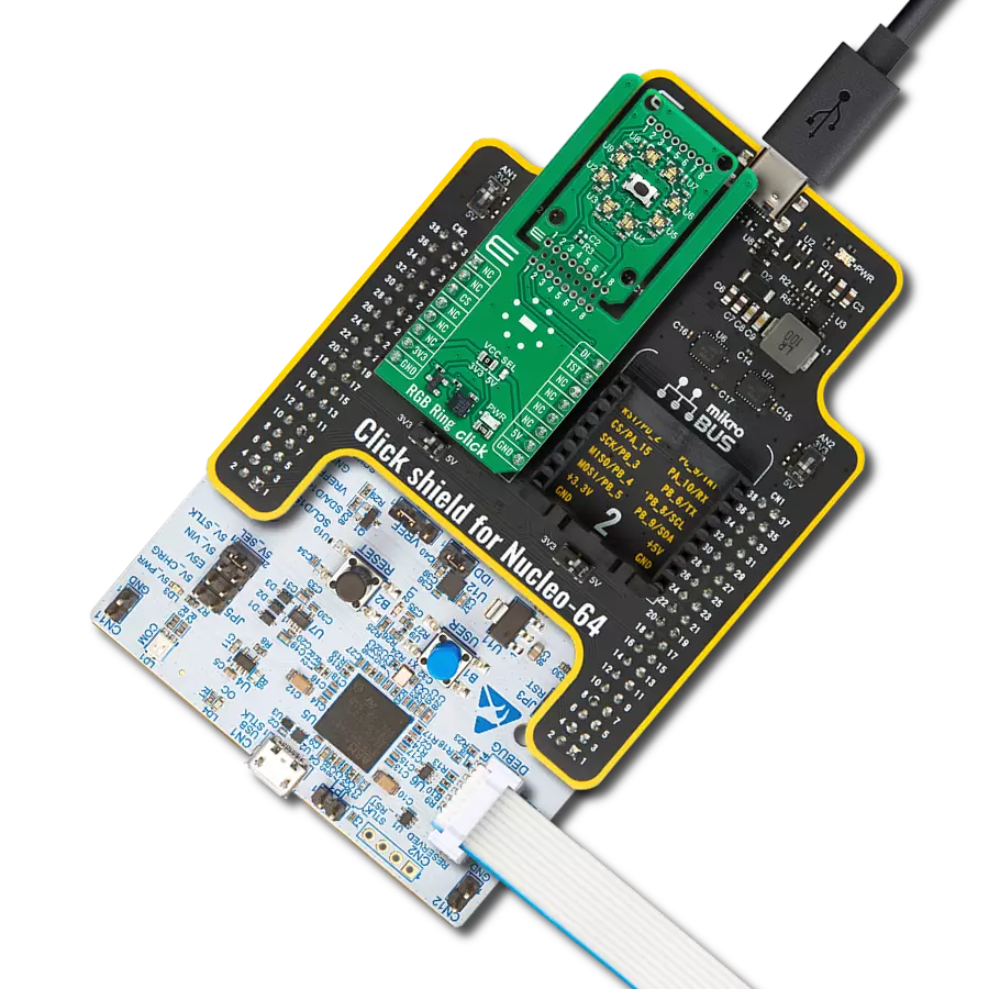
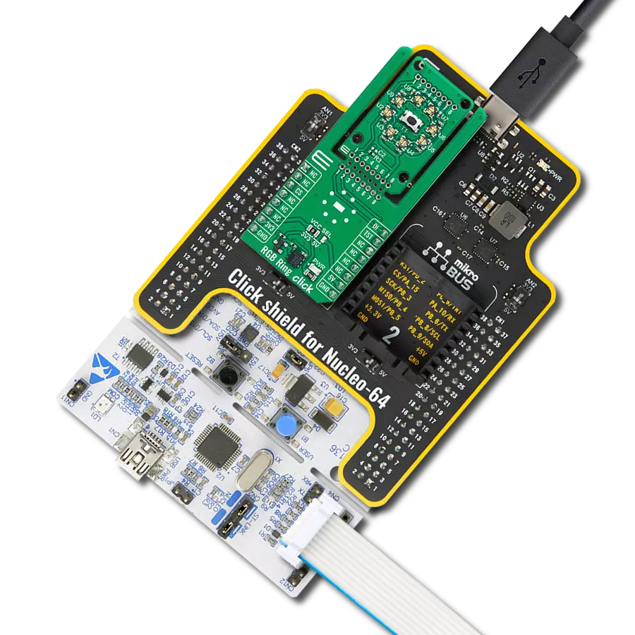
Click Shield for Nucleo-32是扩展您的开发板功能的理想选择,专为STM32 Nucleo-32引脚布局设计。Click Shield for Nucleo-32提供了两个mikroBUS™插座,可以添加来自我们不断增长的Click板™系列中的任何功能。从传感器和WiFi收发器到电机控制和音频放大器,我们应有尽有。Click Shield for Nucleo-32与STM32 Nucleo-32开发板兼容,为用户提供了一种经济且灵活的方式,使用任何STM32微控制器快速创建原型,并尝试各种性能、功耗和功能的组合。STM32 Nucleo-32开发板无需任何独立的探针,因为它集成了ST-LINK/V2-1调试器/编程器,并随附STM32全面的软件HAL库和各种打包的软件示例。这个开发平台为用户提供了一种简便且通用的方式,将STM32 Nucleo-32兼容开发板与他们喜欢的Click板™结合,应用于即将开展的项目中。

使用的MCU引脚
mikroBUS™映射器
“仔细看看!”
Click board™ 原理图
一步一步来
项目组装

从选择您的开发板和Click板™开始。以Nucleo 32 with STM32F031K6 MCU作为您的开发板开始。


实时跟踪您的结果
应用程序输出
1. 应用程序输出 - 在调试模式下,“应用程序输出”窗口支持实时数据监控,直接提供执行结果的可视化。请按照提供的教程正确配置环境,以确保数据正确显示。

2. UART 终端 - 使用UART Terminal通过USB to UART converter监视数据传输,实现Click board™与开发系统之间的直接通信。请根据项目需求配置波特率和其他串行设置,以确保正常运行。有关分步设置说明,请参考提供的教程。

3. Plot 输出 - Plot功能提供了一种强大的方式来可视化实时传感器数据,使趋势分析、调试和多个数据点的对比变得更加直观。要正确设置,请按照提供的教程,其中包含使用Plot功能显示Click board™读数的分步示例。在代码中使用Plot功能时,请使用以下函数:plot(insert_graph_name, variable_name);。这是一个通用格式,用户需要将“insert_graph_name”替换为实际图表名称,并将“variable_name”替换为要显示的参数。

软件支持
库描述
该库包含 2x4 RGB Click 驱动程序的 API。
关键功能:
c2x4rgb_set_leds_intensity- 此函数设置LED矩阵中所有LED的亮度和电流增益级别。c2x4rgb_set_led_color- 此函数设置LED矩阵中选定LED的颜色。c2x4rgb_write_led_matrix- 此函数从click上下文对象中写入LED矩阵数据。
开源
代码示例
完整的应用程序代码和一个现成的项目可以通过NECTO Studio包管理器直接安装到NECTO Studio。 应用程序代码也可以在MIKROE的GitHub账户中找到。
/*!
 * @file main.c
 * @brief 2x4 RGB Click Example.
 *
 * # Description
 * This example demonstrates the use of 2x4 RGB Click board by cycling through
 * a set of colors, gradually increasing the brightness of each LED in a sequence,
 * and then decreasing the brightness before moving on to the next color in the array.
 *
 * The demo application is composed of two sections :
 *
 * ## Application Init
 * Initializes the driver and performs the Click default configuration which sets
 * the LEDs brightness and current gain to a minimum and the color to black (all LEDs off).
 *
 * ## Application Task
 * Cycles through a set of colors, gradually increases the brightness of each LED
 * in a sequence, and then decreases the brightness before moving on to the next
 * color in the array. The current color's name and RGB value are logged to the USB UART.
 *
 * @author Stefan Filipovic
 *
 */

#include "board.h"
#include "log.h"
#include "c2x4rgb.h"
#include "c2x4rgb_delays.h"

static c2x4rgb_t c2x4rgb;   /**< 2x4 RGB Click driver object. */
static log_t logger;    /**< Logger object. */

static c2x4rgb_color_t color[ C2X4RGB_NUM_COLORS ] =
{
    { C2X4RGB_COLOR_BLACK, "BLACK" },
    { C2X4RGB_COLOR_WHITE, "WHITE" },
    { C2X4RGB_COLOR_RED, "RED" },
    { C2X4RGB_COLOR_LIME, "LIME" },
    { C2X4RGB_COLOR_BLUE, "BLUE" },
    { C2X4RGB_COLOR_YELLOW, "YELLOW" },
    { C2X4RGB_COLOR_CYAN, "CYAN" },
    { C2X4RGB_COLOR_MAGENTA, "MAGENTA" },
    { C2X4RGB_COLOR_SILVER, "SILVER" },
    { C2X4RGB_COLOR_GRAY, "GRAY" },
    { C2X4RGB_COLOR_MAROON, "MAROON" },
    { C2X4RGB_COLOR_OLIVE, "OLIVE" },
    { C2X4RGB_COLOR_GREEN, "GREEN" },
    { C2X4RGB_COLOR_PURPLE, "PURPLE" },
    { C2X4RGB_COLOR_TEAL, "TEAL" },
    { C2X4RGB_COLOR_NAVY, "NAVY" }
};

/**
 * @brief 2x4 RGB logic zero function.
 * @details This function toggles the data pin with exact high and low time pulse for logic zero.
 * @return None.
 * @note None.
 */
static void c2x4rgb_logic_zero ( void );

/**
 * @brief 2x4 RGB logic one function.
 * @details This function toggles the data pin with exact high and low time pulse for logic one.
 * @return None.
 * @note None.
 */
static void c2x4rgb_logic_one ( void );

void application_init ( void )
{
    log_cfg_t log_cfg;  /**< Logger config object. */
    c2x4rgb_cfg_t c2x4rgb_cfg;  /**< Click config object. */

    /**
     * Logger initialization.
     * Default baud rate: 115200
     * Default log level: LOG_LEVEL_DEBUG
     * @note If USB_UART_RX and USB_UART_TX
     * are defined as HAL_PIN_NC, you will
     * need to define them manually for log to work.
     * See @b LOG_MAP_USB_UART macro definition for detailed explanation.
     */
    LOG_MAP_USB_UART( log_cfg );
    log_init( &logger, &log_cfg );
    log_info( &logger, " Application Init " );

    // Click initialization.
    c2x4rgb_cfg_setup( &c2x4rgb_cfg );
    C2X4RGB_MAP_MIKROBUS( c2x4rgb_cfg, MIKROBUS_1 );
    if ( DIGITAL_OUT_UNSUPPORTED_PIN ==
         c2x4rgb_init( &c2x4rgb, &c2x4rgb_logic_zero, &c2x4rgb_logic_one, &c2x4rgb_cfg ) )
    {
        log_error( &logger, " Communication init." );
        for ( ; ; );
    }

    if ( C2X4RGB_ERROR == c2x4rgb_default_cfg ( &c2x4rgb ) )
    {
        log_error( &logger, " Default configuration." );
        for ( ; ; );
    }

    log_info( &logger, " Application Task " );
}

void application_task ( void )
{
    static uint32_t color_num = 0;
    static int8_t led_cnt = 0;
    static int8_t brightness = 0;
    log_printf( &logger, " Color: %s [%.6LX]\r\n\n", color[ color_num ].name, color[ color_num ].rgb );
    Delay_ms ( 100 );
    c2x4rgb_set_leds_intensity ( &c2x4rgb, C2X4RGB_LED_BRIGHTNESS_MIN, C2X4RGB_LED_CURRENT_GAIN_DEFAULT );
    for ( led_cnt = C2X4RGB_LED_7; led_cnt >= C2X4RGB_LED_0; led_cnt-- )
    {
        c2x4rgb_set_led_color ( &c2x4rgb, led_cnt, color[ color_num ].rgb );
        c2x4rgb_write_led_matrix ( &c2x4rgb );
        Delay_ms ( 100 );
    }
    for ( brightness = C2X4RGB_LED_BRIGHTNESS_MIN; brightness < C2X4RGB_LED_BRIGHTNESS_MAX; brightness++ )
    {
        c2x4rgb_set_leds_intensity ( &c2x4rgb, brightness, C2X4RGB_LED_CURRENT_GAIN_DEFAULT );
        c2x4rgb_write_led_matrix ( &c2x4rgb );
        Delay_ms ( 50 );
    }
    for ( brightness = C2X4RGB_LED_BRIGHTNESS_MAX; brightness >= C2X4RGB_LED_BRIGHTNESS_MIN; brightness-- )
    {
        c2x4rgb_set_leds_intensity ( &c2x4rgb, brightness, C2X4RGB_LED_CURRENT_GAIN_DEFAULT );
        c2x4rgb_write_led_matrix ( &c2x4rgb );
        Delay_ms ( 50 );
    }
    if ( ++color_num >= C2X4RGB_NUM_COLORS )
    {
        color_num = 0;
    }
}

int main ( void )
{
    /* Do not remove this line or clock might not be set correctly. */
    #ifdef PREINIT_SUPPORTED
    preinit();
    #endif

    application_init( );

    for ( ; ; )
    {
        application_task( );
    }

    return 0;
}

static void c2x4rgb_logic_zero ( void )
{
    hal_ll_gpio_set_pin_output( &c2x4rgb.din.pin );
    DELAY_TOH;
    hal_ll_gpio_clear_pin_output( &c2x4rgb.din.pin );
    DELAY_TOL;
}

static void c2x4rgb_logic_one ( void )
{
    hal_ll_gpio_set_pin_output( &c2x4rgb.din.pin );
    DELAY_T1H;
    hal_ll_gpio_clear_pin_output( &c2x4rgb.din.pin );
    DELAY_T1L;
}

// ------------------------------------------------------------------------ END
额外支持
资源
类别:LED 矩阵