使用TC78H660FTG和STM32F031K6设计更高效的电机驱动系统
体验前所未有的电机控制

已发布 10月 01, 2024
点击板
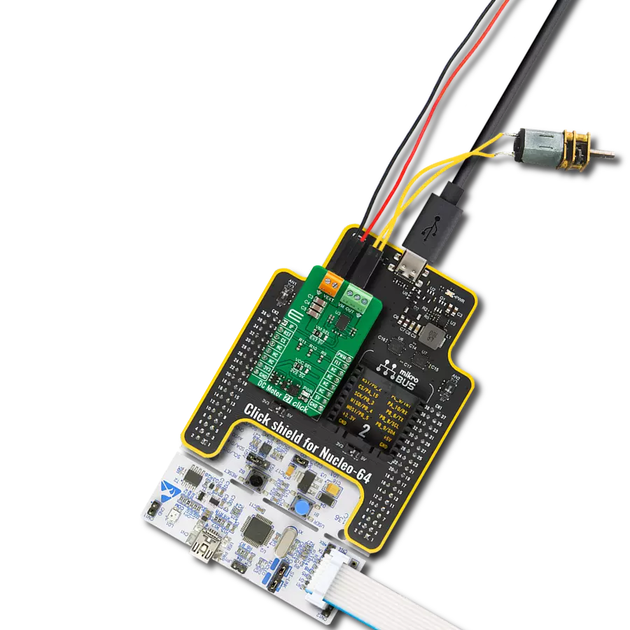
DC Motor 17 Click
开发板
Nucleo 32 with STM32F031K6 MCU
编译器
NECTO Studio
微控制器单元
STM32F031K6
体验不同。添加有刷电机控制,见证您的项目转变,提高速度、精度和整体潜力!
A
A
硬件概览
它是如何工作的?
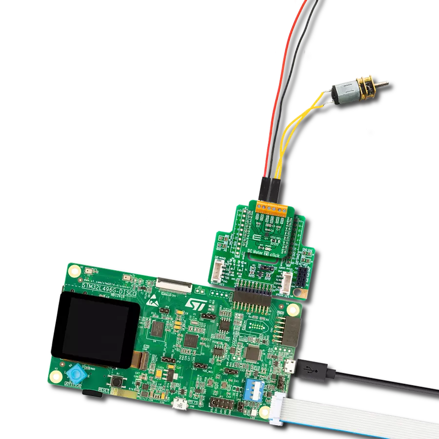
DC Motor 17 Click 基于TC78H660FTG,这是一款来自东芝半导体的双H桥驱动器,用于一个或两个直流有刷电机,采用低导通电阻的DMOS输出晶体管。该驱动器是一个PWM控制的恒流驱动,供电电压范围为2.5至16V,最大输出电流为2A。它具有内置的双H桥、无感电阻的电流控制架构(高级电流检测系统)和内部电路的VCC稳压器。此外,它还提供热关断、过流检测、欠压锁定错误检测(带错误检测标志功能)以及由四个GPIO引脚控制的几种可选操作模式(前进、后退、停止和制动),这些引脚通过mikroBUS™插座的RST、AN、PWM和INT引脚连接。TC78H660FTG具有两种操作模式,IN输入模式和PHASE输入模式,可通过标记为MODE的控制模式引脚选择。PHASE模式是此Click板™的默认模式,控制模式由释放SBY引脚后的MODE引脚的输入状态设置。通过这种方式,MODE引脚用作使能信
号,而方向选择通过mikroBUS™插座上的GPIO引脚实现。标记为ERR的引脚表示错误检测标志。当TC78H660FTG检测到一些错误时,ERR引脚向外设模块输出低电平。在正常状态下,由于内部MOSFET关闭,ERR引脚的逻辑电平等于外部的MODE控制电压。当发生热关断或过流等事件时,ERR引脚将变为低电平(内部MOSFET开启)。当通过重新加电或将设备设置为待机模式释放错误检测时,ERR引脚显示正常状态。在恒流控制的情况下,确定电流波动的混合衰减模式的比例固定为37.5%。峰值电流可以通过MAX6100(Analog Devices提供的一款低成本、低压差、微功率电压基准IC)获得的VREF引脚的电压值来设置。该系列模式电压基准仅消耗90μA的供电电流,能够提供5mA的源电流和2mA的灌电流。通过标记为VR1的板载微调器,可以手动设置TC78H660FTG的VREF引脚的电流阈值。正如
产品描述中提到的,DC Motor 17 Click通过几个GPIO引脚与MCU通信。此外,这个Click板™还有一个标记为SBY的待机引脚,该引脚连接到mikroBUS™插座的CS引脚,用于通过切换引脚进入待机模式。当SBY引脚为低电平时,TC78H660FTG停止向逻辑电路供电。需要特别强调的是,IN和PHASE输入模式之间的直流电机模式的区别。除了前进、后退、停止和待机等电机模式外,只有IN输入模式具有另一个额外的短制动模式。有关电机模式选择的更多信息可以在附带的数据表中找到。此Click板™可以通过VCC SEL跳线选择3.3V或5V逻辑电压等级。这样,3.3V和5V能力的MCU都可以正确使用通信线。此外,还可以通过标记为VM SEL的跳线选择电机驱动电源,从2.5到16V范围内的外部输入端子供电,或使用来自mikroBUS™供电引脚的电压等级。

功能概述
开发板
Nucleo 32开发板搭载STM32F031K6 MCU,提供了一种经济且灵活的平台,适用于使用32引脚封装的STM32微控制器进行实验。该开发板具有Arduino™ Nano连接性,便于通过专用扩展板进行功能扩展,并且支持mbed,使其能够无缝集成在线资源。板载集成
ST-LINK/V2-1调试器/编程器,支持通过USB重新枚举,提供三种接口:虚拟串口(Virtual Com port)、大容量存储和调试端口。该开发板的电源供应灵活,可通过USB VBUS或外部电源供电。此外,还配备了三个LED指示灯(LD1用于USB通信,LD2用于电源
指示,LD3为用户可控LED)和一个复位按钮。STM32 Nucleo-32开发板支持多种集成开发环境(IDEs),如IAR™、Keil®和基于GCC的IDE(如AC6 SW4STM32),使其成为开发人员的多功能工具。

微控制器概述
MCU卡片 / MCU

建筑
ARM Cortex-M0
MCU 内存 (KB)
32
硅供应商
STMicroelectronics
引脚数
32
RAM (字节)
4096
你完善了我!
配件
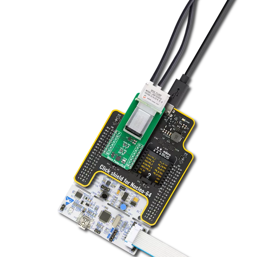
Click Shield for Nucleo-32是扩展您的开发板功能的理想选择,专为STM32 Nucleo-32引脚布局设计。Click Shield for Nucleo-32提供了两个mikroBUS™插座,可以添加来自我们不断增长的Click板™系列中的任何功能。从传感器和WiFi收发器到电机控制和音频放大器,我们应有尽有。Click Shield for Nucleo-32与STM32 Nucleo-32开发板兼容,为用户提供了一种经济且灵活的方式,使用任何STM32微控制器快速创建原型,并尝试各种性能、功耗和功能的组合。STM32 Nucleo-32开发板无需任何独立的探针,因为它集成了ST-LINK/V2-1调试器/编程器,并随附STM32全面的软件HAL库和各种打包的软件示例。这个开发平台为用户提供了一种简便且通用的方式,将STM32 Nucleo-32兼容开发板与他们喜欢的Click板™结合,应用于即将开展的项目中。

直流齿轮电机 - 430RPM (3-6V) 代表了电机和齿轮箱的一体化组合,其中齿轮的加入导致电机速度降低而扭矩输出增加。该齿轮电机具有一个齿轮箱,使其成为低扭矩和速度要求应用的高度可靠的解决方案。齿轮电机最关键的参数是速度、扭矩和效率,在这种情况下,无负载时速度为520RPM,最大效率时为430RPM,电流为60mA,扭矩为50g.cm。额定工作电压范围为3-6V,旋转方向为顺时针/逆时针,这种电机是最初由有刷直流电机执行的许多功能的优秀解决方案,广泛应用于机器人、医疗设备、电动门锁等领域。

使用的MCU引脚
mikroBUS™映射器
“仔细看看!”
Click board™ 原理图

一步一步来
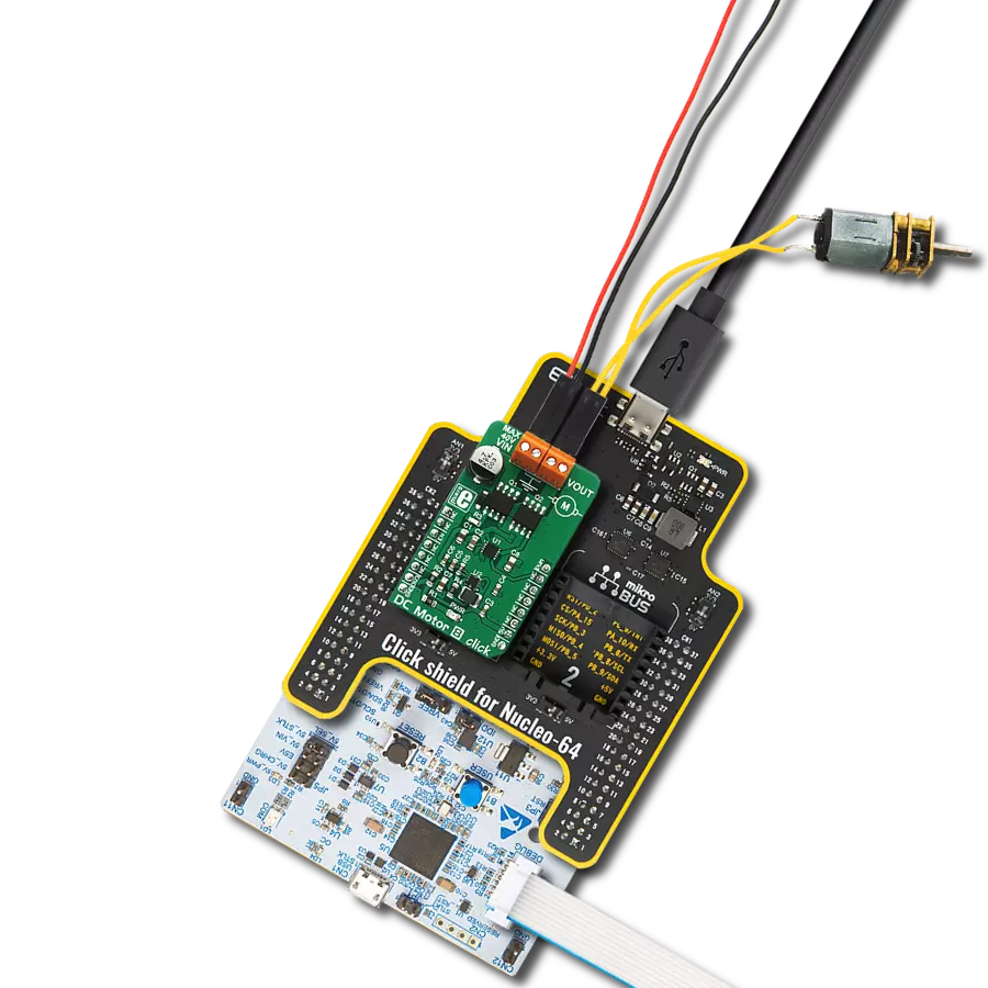
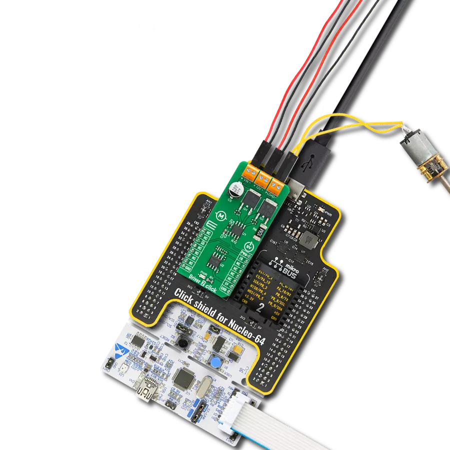
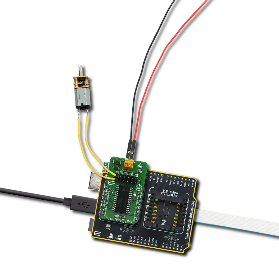
项目组装

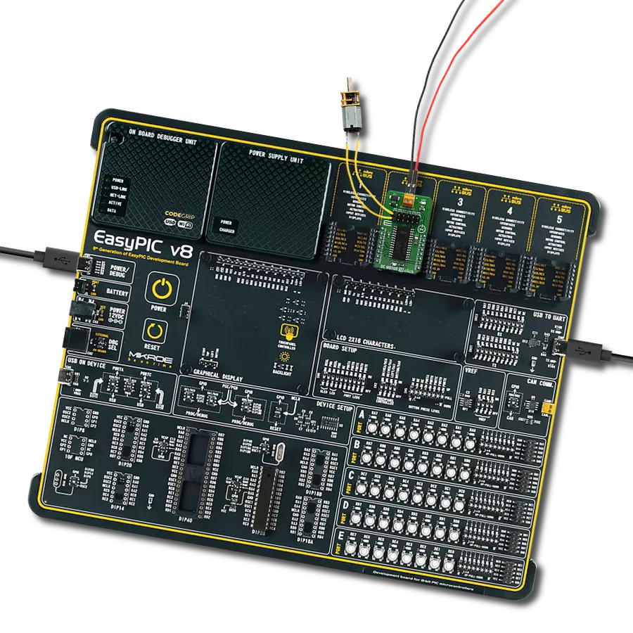
从选择您的开发板和Click板™开始。以Nucleo 32 with STM32F031K6 MCU作为您的开发板开始。


实时跟踪您的结果
应用程序输出
1. 应用程序输出 - 在调试模式下,“应用程序输出”窗口支持实时数据监控,直接提供执行结果的可视化。请按照提供的教程正确配置环境,以确保数据正确显示。

2. UART 终端 - 使用UART Terminal通过USB to UART converter监视数据传输,实现Click board™与开发系统之间的直接通信。请根据项目需求配置波特率和其他串行设置,以确保正常运行。有关分步设置说明,请参考提供的教程。

3. Plot 输出 - Plot功能提供了一种强大的方式来可视化实时传感器数据,使趋势分析、调试和多个数据点的对比变得更加直观。要正确设置,请按照提供的教程,其中包含使用Plot功能显示Click board™读数的分步示例。在代码中使用Plot功能时,请使用以下函数:plot(insert_graph_name, variable_name);。这是一个通用格式,用户需要将“insert_graph_name”替换为实际图表名称,并将“variable_name”替换为要显示的参数。

软件支持
库描述
该库包含 DC Motor 17 Click 驱动程序的 API。
关键功能:
dcmotor17_stop- 直流电机17停止电机功能dcmotor17_forward- 直流电机17前进功能dcmotor17_reverse- 直流电机17倒车功能
开源
代码示例
完整的应用程序代码和一个现成的项目可以通过NECTO Studio包管理器直接安装到NECTO Studio。 应用程序代码也可以在MIKROE的GitHub账户中找到。
/*!
 * @file main.c
 * @brief DC Motor 17 Click Example.
 *
 * # Description
 * The library covers all the necessary functions to control DC Motor 17 Click board.
 * Library performs a standard GPIO interface communication.
 * DC Motor 17 Click board is a dual H Bridge driver IC for one or two DC brushed
 * motors which incorporates DMOS with low on-resistance in output transistors.
 *
 * The demo application is composed of two sections :
 *
 * ## Application Init
 * Initializes GPIO driver, set default configuration and start to write log.
 *
 * ## Application Task
 * This is an example that demonstrates the use of the DC Motor 17 Click board.
 * This example demonstrates the use of DC Motor 17 Click,
 * we first control motion A by driving it forward motion for 5 seconds,
 * than applying short brakes it for 2 second, then driving it in reverse for 5 seconds
 * and stop the motor for 2 seconds.
 * In the second part of the example, we control motion B by the same principle.
 * Results are being sent to the Usart Terminal where you can track their changes.
 *
 * @author Nenad Filipovic
 *
 */

#include "board.h"
#include "log.h"
#include "dcmotor17.h"

static dcmotor17_t dcmotor17;   /**< DC Motor 17 Click driver object. */
static log_t logger;            /**< Logger object. */

void application_init ( void ) {
    log_cfg_t log_cfg;              /**< Logger config object. */
    dcmotor17_cfg_t dcmotor17_cfg;  /**< Click config object. */

    /**
     * Logger initialization.
     * Default baud rate: 115200
     * Default log level: LOG_LEVEL_DEBUG
     * @note If USB_UART_RX and USB_UART_TX
     * are defined as HAL_PIN_NC, you will
     * need to define them manually for log to work.
     * See @b LOG_MAP_USB_UART macro definition for detailed explanation.
     */
    LOG_MAP_USB_UART( log_cfg );
    log_init( &logger, &log_cfg );
    log_printf( &logger, "----------------------------\r\n" );
    log_printf( &logger, "      DC Motor 17 Click     \r\n" );
    log_printf( &logger, "----------------------------\r\n" );
    log_info( &logger, " Application Init " );

    // Click initialization.

    dcmotor17_cfg_setup( &dcmotor17_cfg );
    DCMOTOR17_MAP_MIKROBUS( dcmotor17_cfg, MIKROBUS_1 );
    if ( dcmotor17_init( &dcmotor17, &dcmotor17_cfg ) == DIGITAL_OUT_UNSUPPORTED_PIN ) {
        log_error( &logger, " Application Init Error. " );
        log_info( &logger, " Please, run program again... " );

        for ( ; ; );
    }
    dcmotor17_default_cfg ( &dcmotor17 );
    log_info( &logger, " Application Task " );
}

void application_task ( void ) {
    log_printf( &logger, "----------------------------\r\n" );
    log_printf( &logger, "          Motor A           \r\n" );
    log_printf( &logger, "----------------------------\r\n" );
    log_printf( &logger, "  Start the motor forward.  \r\n" );
    dcmotor17_forward( &dcmotor17, DCMOTOR17_SEL_OUT_A );
    Delay_ms ( 1000 );
    Delay_ms ( 1000 );
    Delay_ms ( 1000 );
    Delay_ms ( 1000 );
    Delay_ms ( 1000 );

    log_printf( &logger, "----------------------------\r\n" );
    log_printf( &logger, "       Stop the motor.      \r\n" );
    dcmotor17_stop( &dcmotor17, DCMOTOR17_SEL_OUT_A );
    Delay_ms ( 1000 );
    Delay_ms ( 1000 );

    log_printf( &logger, "----------------------------\r\n" );
    log_printf( &logger, "  Start the motor reverse.  \r\n" );
    dcmotor17_reverse( &dcmotor17, DCMOTOR17_SEL_OUT_A );
    Delay_ms ( 1000 );
    Delay_ms ( 1000 );
    Delay_ms ( 1000 );
    Delay_ms ( 1000 );
    Delay_ms ( 1000 );

    log_printf( &logger, "----------------------------\r\n" );
    log_printf( &logger, "       Stop the motor.      \r\n" );
    dcmotor17_stop( &dcmotor17, DCMOTOR17_SEL_OUT_A );
    Delay_ms ( 1000 );
    Delay_ms ( 1000 );

    log_printf( &logger, "----------------------------\r\n" );
    log_printf( &logger, "          Motor B           \r\n" );
    log_printf( &logger, "----------------------------\r\n" );
    log_printf( &logger, "  Start the motor forward.  \r\n" );
    dcmotor17_forward( &dcmotor17, DCMOTOR17_SEL_OUT_B );
    Delay_ms ( 1000 );
    Delay_ms ( 1000 );
    Delay_ms ( 1000 );
    Delay_ms ( 1000 );
    Delay_ms ( 1000 );

    log_printf( &logger, "----------------------------\r\n" );
    log_printf( &logger, "       Stop the motor.      \r\n" );
    dcmotor17_stop( &dcmotor17, DCMOTOR17_SEL_OUT_B );
    Delay_ms ( 1000 );
    Delay_ms ( 1000 );

    log_printf( &logger, "----------------------------\r\n" );
    log_printf( &logger, "  Start the motor reverse.  \r\n" );
    dcmotor17_reverse( &dcmotor17, DCMOTOR17_SEL_OUT_B );
    Delay_ms ( 1000 );
    Delay_ms ( 1000 );
    Delay_ms ( 1000 );
    Delay_ms ( 1000 );
    Delay_ms ( 1000 );

    log_printf( &logger, "----------------------------\r\n" );
    log_printf( &logger, "       Stop the motor.      \r\n" );
    dcmotor17_stop( &dcmotor17, DCMOTOR17_SEL_OUT_B );
    Delay_ms ( 1000 );
    Delay_ms ( 1000 );
}

int main ( void )
{
    /* Do not remove this line or clock might not be set correctly. */
    #ifdef PREINIT_SUPPORTED
    preinit();
    #endif

    application_init( );

    for ( ; ; )
    {
        application_task( );
    }

    return 0;
}

// ------------------------------------------------------------------------ END