使用ESP32-C3-MINI-1-N4-A和STM32F031K6简化安全设备到云端的连接
物联网ExpressLink:将普通项目变为非凡的物联网解决方案

已发布 10月 01, 2024
点击板
IoT ExpressLink Click
开发板
Nucleo 32 with STM32F031K6 MCU
编译器
NECTO Studio
微控制器单元
STM32F031K6
出于对简单性和安全性的承诺,我们的目标是让用户轻松将他们的设备安全地连接到云端,并无缝集成AWS服务的丰富功能。
A
A
硬件概览
它是如何工作的?
IoT ExpressLink Click 基于 Espressif Systems 的 ESP32-C3-MINI-1-N4-A,这是一个 2.4GHz WiFi(802.11 b/g/n)和 Bluetooth® 5 LE 组合模块,配备板载 PCB 天线和 AWS IoT ExpressLink 固件(锁定到 AWS)。该模块的核心是 ESP32C3 系列 SoC RISCV 单核 32 位微处理器(ESP32-C3FN4),该芯片嵌入了 4MB 的闪存,时钟速度高达 160MHz。由于闪存在 ESP32-C3FN4 芯片中封装而不是集成在模块中,因此 ESP32-C3-MINI-1-N4-A 具有较小的封装尺寸。凭借其丰富的功能集,能够实现 IoT ExpressLink 服务,该 Click board™ 非常适合智能家
居、工业自动化、医疗保健、消费电子和通用 IoT 传感器集线器及数据记录应用。IoT ExpressLink Click 通过 UART 通信与主机 MCU 进行接口通信,涉及使用 RX 和 TX 引脚发送 AT 命令,操作速率为 115200bps。除了 UART 引脚外,此 Click board™ 还利用了 mikroBUS™ 插座的其他引脚来增强其功能。例如,WK 引脚用作模块唤醒引脚,EVT 引脚用于检测操作期间的重大事件,设备使能引脚 RST 提供一个用于打开/关闭模块的开关操作。在板子的左侧,可以找到一个额外的未填充接头,该接头提供对调试功能的全面支持。通过此接头,用户可以使用 JTAG
接口进行调试,通过 JTAG 接口引脚(TDO、TCK、TDI 和 TMS)提供支持。在板子的右侧,还有一组未填充的接头,例如用于调试的额外 UART 引脚和具有用户可配置通用输入输出引脚的接头。此 Click board™ 只能在 3.3V 逻辑电压水平下操作。在使用具有不同逻辑电平的 MCU 之前,必须执行适当的逻辑电压电平转换。此外,这款 Click board™ 配备了包含易用功能的库和示例代码,可作为进一步开发的参考。

功能概述
开发板
Nucleo 32开发板搭载STM32F031K6 MCU,提供了一种经济且灵活的平台,适用于使用32引脚封装的STM32微控制器进行实验。该开发板具有Arduino™ Nano连接性,便于通过专用扩展板进行功能扩展,并且支持mbed,使其能够无缝集成在线资源。板载集成
ST-LINK/V2-1调试器/编程器,支持通过USB重新枚举,提供三种接口:虚拟串口(Virtual Com port)、大容量存储和调试端口。该开发板的电源供应灵活,可通过USB VBUS或外部电源供电。此外,还配备了三个LED指示灯(LD1用于USB通信,LD2用于电源
指示,LD3为用户可控LED)和一个复位按钮。STM32 Nucleo-32开发板支持多种集成开发环境(IDEs),如IAR™、Keil®和基于GCC的IDE(如AC6 SW4STM32),使其成为开发人员的多功能工具。

微控制器概述
MCU卡片 / MCU

建筑
ARM Cortex-M0
MCU 内存 (KB)
32
硅供应商
STMicroelectronics
引脚数
32
RAM (字节)
4096
你完善了我!
配件
Click Shield for Nucleo-32是扩展您的开发板功能的理想选择,专为STM32 Nucleo-32引脚布局设计。Click Shield for Nucleo-32提供了两个mikroBUS™插座,可以添加来自我们不断增长的Click板™系列中的任何功能。从传感器和WiFi收发器到电机控制和音频放大器,我们应有尽有。Click Shield for Nucleo-32与STM32 Nucleo-32开发板兼容,为用户提供了一种经济且灵活的方式,使用任何STM32微控制器快速创建原型,并尝试各种性能、功耗和功能的组合。STM32 Nucleo-32开发板无需任何独立的探针,因为它集成了ST-LINK/V2-1调试器/编程器,并随附STM32全面的软件HAL库和各种打包的软件示例。这个开发平台为用户提供了一种简便且通用的方式,将STM32 Nucleo-32兼容开发板与他们喜欢的Click板™结合,应用于即将开展的项目中。

使用的MCU引脚
mikroBUS™映射器
“仔细看看!”
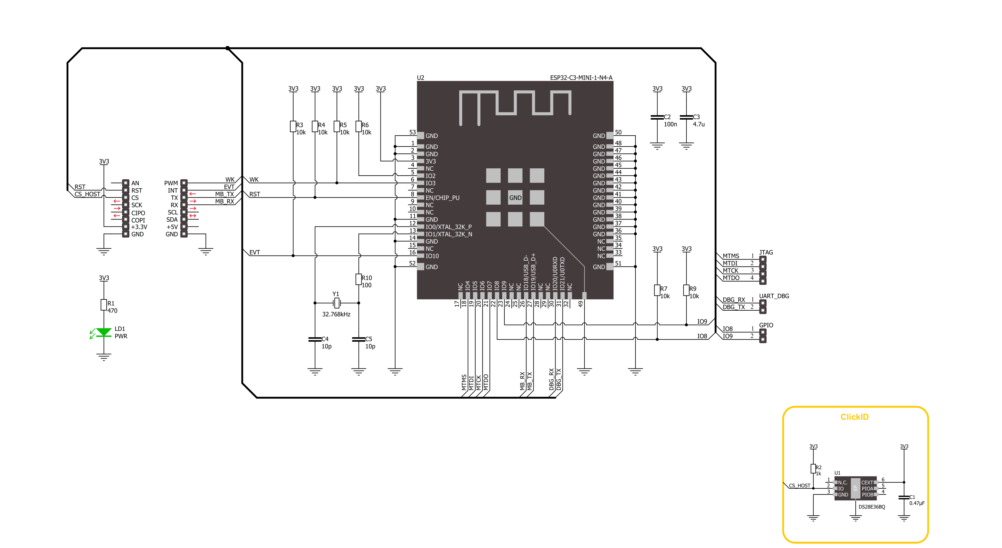
Click board™ 原理图
一步一步来
项目组装

从选择您的开发板和Click板™开始。以Nucleo 32 with STM32F031K6 MCU作为您的开发板开始。


实时跟踪您的结果
应用程序输出
1. 应用程序输出 - 在调试模式下,“应用程序输出”窗口支持实时数据监控,直接提供执行结果的可视化。请按照提供的教程正确配置环境,以确保数据正确显示。

2. UART 终端 - 使用UART Terminal通过USB to UART converter监视数据传输,实现Click board™与开发系统之间的直接通信。请根据项目需求配置波特率和其他串行设置,以确保正常运行。有关分步设置说明,请参考提供的教程。

3. Plot 输出 - Plot功能提供了一种强大的方式来可视化实时传感器数据,使趋势分析、调试和多个数据点的对比变得更加直观。要正确设置,请按照提供的教程,其中包含使用Plot功能显示Click board™读数的分步示例。在代码中使用Plot功能时,请使用以下函数:plot(insert_graph_name, variable_name);。这是一个通用格式,用户需要将“insert_graph_name”替换为实际图表名称,并将“variable_name”替换为要显示的参数。

软件支持
库描述
该库包含 IoT ExpressLink Click 驱动程序的 API。
关键功能:
iotexpresslink_reset_device- 该函数通过切换RST引脚状态来重置设备。iotexpresslink_send_cmd- 该函数通过使用UART串行接口发送命令字符串。
开源
代码示例
完整的应用程序代码和一个现成的项目可以通过NECTO Studio包管理器直接安装到NECTO Studio。 应用程序代码也可以在MIKROE的GitHub账户中找到。
/*!
 * @file main.c
 * @brief IoT ExpressLink Click Example.
 *
 * # Description
 * This example demonstrates the use of IoT ExpressLink click board by bridging the USB UART
 * to mikroBUS UART which allows the click board to establish a connection with
 * the IoT ExpressLink over the Quick Connect demo application without an AWS account.
 *
 * The demo application is composed of two sections :
 *
 * ## Application Init
 * Initializes the driver, resets the click board to factory default settings, reads
 * and displays the vendor model and thing name on the USB UART, sets the WiFi credentials,
 * and attempts to connect to the AWS Cloud. If the initial attempt fails and the error
 * message "Failed to access network" or "Failed to login AWS (MQTT) broker" appears,
 * check the WiFi credentials and try running the example again.
 *
 * ## Application Task
 * All data received from the USB UART will be forwarded to mikroBUS UART, and vice versa.
 * At this point you should disconnect from the UART terminal and run the Quick Connect
 * demo application.
 *
 * ## Additional Function
 * - static void iotexpresslink_clear_app_buf ( void )
 * - static err_t iotexpresslink_process ( uart_t *uart )
 * - static err_t iotexpresslink_read_response ( iotexpresslink_t *ctx )
 *
 * @note
 * To run the demo, follow the below steps:
 * 1. If you opened a terminal application in the previous step, be sure to disconnect that
 *    application from the serial port.
 * 2. Download the Quick Connect executable:
 *    Mac: https://quickconnectexpresslinkutility.s3.us-west-2.amazonaws.com/QuickConnect_v1.9_macos.x64.tar.gz
 *    Windows: https://quickconnectexpresslinkutility.s3.us-west-2.amazonaws.com/QuickConnect_v1.9_windows.x64.zip
 *    Linux: https://quickconnectexpresslinkutility.s3.us-west-2.amazonaws.com/QuickConnect_v1.9_linux.x64.tar.gz
 * 3. Unzip the package, and follow the steps from the README file.
 *
 * The demo will connect to IoT ExpressLink and give you an URL that you can use to visualize data
 * flowing from the device to the cloud using AT+SEND commands. The demo will run for up
 * to two minutes, and afterwards, you will be able to type AT+SEND commands yourself and
 * see the data coming in on the visualizer.
 *
 * @author Stefan Filipovic
 *
 */

#include "board.h"
#include "log.h"
#include "iotexpresslink.h"

#define PROCESS_BUFFER_SIZE 500

// Enter valid WiFi credentials below
#define WIFI_SSID   "MikroE Public"     // WiFi SSID
#define WIFI_PASS   "mikroe.guest"      // WiFi Password

static iotexpresslink_t iotexpresslink;
static log_t logger;

static uint8_t app_buf[ PROCESS_BUFFER_SIZE ] = { 0 };
static int32_t app_buf_len = 0;

/**
 * @brief IoT ExpressLink clearing application buffer.
 * @details This function clears memory of application buffer and reset its length.
 * @note None.
 */
static void iotexpresslink_clear_app_buf ( void );

/**
 * @brief IoT ExpressLink data reading function.
 * @details This function reads data from device and concatenates data to application buffer.
 * @param[in] ctx : Click context object.
 * See #iotexpresslink_t object definition for detailed explanation.
 * @return @li @c  0 - Read some data.
 *         @li @c -1 - Nothing is read.
 * See #err_t definition for detailed explanation.
 * @note None.
 */
static err_t iotexpresslink_process ( iotexpresslink_t *ctx ) ;

/**
 * @brief IoT ExpressLink read response function.
 * @details This function waits for a response message, reads and displays it on the USB UART.
 * @param[in] ctx : Click context object.
 * See #iotexpresslink_t object definition for detailed explanation.
 * @return @li @c  0 - OK response.
 *         @li @c -2 - Timeout error.
 *         @li @c -3 - Command error.
 *         @li @c -4 - Unknown error.
 * See #err_t definition for detailed explanation.
 * @note None.
 */
static err_t iotexpresslink_read_response ( iotexpresslink_t *ctx );

void application_init ( void )
{
    log_cfg_t log_cfg;  /**< Logger config object. */
    iotexpresslink_cfg_t iotexpresslink_cfg;  /**< Click config object. */

    /**
     * Logger initialization.
     * Default baud rate: 115200
     * Default log level: LOG_LEVEL_DEBUG
     * @note If USB_UART_RX and USB_UART_TX
     * are defined as HAL_PIN_NC, you will
     * need to define them manually for log to work.
     * See @b LOG_MAP_USB_UART macro definition for detailed explanation.
     */
    LOG_MAP_USB_UART( log_cfg );
    log_init( &logger, &log_cfg );
    log_info( &logger, " Application Init " );

    // Click initialization.
    iotexpresslink_cfg_setup( &iotexpresslink_cfg );
    IOTEXPRESSLINK_MAP_MIKROBUS( iotexpresslink_cfg, MIKROBUS_1 );
    if ( UART_ERROR == iotexpresslink_init( &iotexpresslink, &iotexpresslink_cfg ) )
    {
        log_error( &logger, " Communication init." );
        for ( ; ; );
    }

    log_printf( &logger, "Reset device\r\n\n" );
    iotexpresslink_reset_device ( &iotexpresslink );
    Delay_ms ( 2000 );
    log_printf( &logger, "Factory reset\r\n" );
    strcpy ( app_buf, IOTEXPRESSLINK_CMD_FACTORY_RESET );
    iotexpresslink_send_cmd ( &iotexpresslink, app_buf );
    iotexpresslink_read_response ( &iotexpresslink );
    Delay_ms ( 2000 );

    log_printf( &logger, "Vendor model\r\n" );
    strcpy ( app_buf, IOTEXPRESSLINK_CMD_CONF_CHECK );
    strcat ( app_buf, IOTEXPRESSLINK_CMD_SEPARATOR );
    strcat ( app_buf, IOTEXPRESSLINK_CONF_KEY_ABOUT );
    iotexpresslink_send_cmd ( &iotexpresslink, app_buf );
    iotexpresslink_read_response ( &iotexpresslink );

    log_printf( &logger, "Thing name\r\n" );
    strcpy ( app_buf, IOTEXPRESSLINK_CMD_CONF_CHECK );
    strcat ( app_buf, IOTEXPRESSLINK_CMD_SEPARATOR );
    strcat ( app_buf, IOTEXPRESSLINK_CONF_KEY_THING_NAME );
    iotexpresslink_send_cmd ( &iotexpresslink, app_buf );
    iotexpresslink_read_response ( &iotexpresslink );

    log_printf( &logger, "WiFi SSID\r\n" );
    strcpy ( app_buf, IOTEXPRESSLINK_CMD_CONF );
    strcat ( app_buf, IOTEXPRESSLINK_CMD_SEPARATOR );
    strcat ( app_buf, IOTEXPRESSLINK_CONF_KEY_SSID );
    strcat ( app_buf, IOTEXPRESSLINK_CMD_SIGN_EQUAL );
    strcat ( app_buf, WIFI_SSID );
    iotexpresslink_send_cmd ( &iotexpresslink, app_buf );
    iotexpresslink_read_response ( &iotexpresslink );

    log_printf( &logger, "WiFi Password\r\n" );
    strcpy ( app_buf, IOTEXPRESSLINK_CMD_CONF );
    strcat ( app_buf, IOTEXPRESSLINK_CMD_SEPARATOR );
    strcat ( app_buf, IOTEXPRESSLINK_CONF_KEY_PASSPHRASE );
    strcat ( app_buf, IOTEXPRESSLINK_CMD_SIGN_EQUAL );
    strcat ( app_buf, WIFI_PASS );
    iotexpresslink_send_cmd ( &iotexpresslink, app_buf );
    iotexpresslink_read_response ( &iotexpresslink );

    log_printf( &logger, "Try to connect\r\n" );
    strcpy ( app_buf, IOTEXPRESSLINK_CMD_CONNECT );
    iotexpresslink_send_cmd ( &iotexpresslink, app_buf );
    iotexpresslink_read_response ( &iotexpresslink );

    log_info( &logger, " Application Task " );

    log_printf( &logger, "Now close the UART terminal and switch to the QuickConnect app\r\n" );
    Delay_ms ( 1000 );

    uart_set_blocking( &logger.uart, false );
}

void application_task ( void )
{
    app_buf_len = uart_read( &logger.uart, app_buf, PROCESS_BUFFER_SIZE );
    if ( app_buf_len > 0 )
    {
        uart_write ( &iotexpresslink.uart, app_buf, app_buf_len );
        iotexpresslink_clear_app_buf( );
    }
    app_buf_len = uart_read( &iotexpresslink.uart, app_buf, PROCESS_BUFFER_SIZE );
    if ( app_buf_len > 0 )
    {
        uart_write ( &logger.uart, app_buf, app_buf_len );
        iotexpresslink_clear_app_buf( );
    }
}

void main ( void )
{
    application_init( );

    for ( ; ; )
    {
        application_task( );
    }
}

static void iotexpresslink_clear_app_buf ( void )
{
    memset( app_buf, 0, app_buf_len );
    app_buf_len = 0;
}

static err_t iotexpresslink_process ( iotexpresslink_t *ctx )
{
    uint8_t rx_buf[ PROCESS_BUFFER_SIZE ] = { 0 };
    int32_t rx_size = 0;
    rx_size = iotexpresslink_generic_read( ctx, rx_buf, PROCESS_BUFFER_SIZE );
    if ( rx_size > 0 )
    {
        int32_t buf_cnt = app_buf_len;
        if ( ( ( app_buf_len + rx_size ) > PROCESS_BUFFER_SIZE ) && ( app_buf_len > 0 ) )
        {
            buf_cnt = PROCESS_BUFFER_SIZE - ( ( app_buf_len + rx_size ) - PROCESS_BUFFER_SIZE );
            memmove ( app_buf, &app_buf[ PROCESS_BUFFER_SIZE - buf_cnt ], buf_cnt );
        }
        for ( int32_t rx_cnt = 0; rx_cnt < rx_size; rx_cnt++ )
        {
            if ( rx_buf[ rx_cnt ] )
            {
                app_buf[ buf_cnt++ ] = rx_buf[ rx_cnt ];
                if ( app_buf_len < PROCESS_BUFFER_SIZE )
                {
                    app_buf_len++;
                }
            }
        }
        return IOTEXPRESSLINK_OK;
    }
    return IOTEXPRESSLINK_ERROR;
}

static err_t iotexpresslink_read_response ( iotexpresslink_t *ctx )
{
    uint32_t timeout_cnt = 0;
    uint32_t timeout = 30000;
    memset( app_buf, 0, PROCESS_BUFFER_SIZE );
    app_buf_len = 0;
    iotexpresslink_process( ctx );
    while ( ( 0 == strstr( app_buf, IOTEXPRESSLINK_RSP_OK ) ) &&
            ( 0 == strstr( app_buf, IOTEXPRESSLINK_RSP_ERR ) ) )
    {
        iotexpresslink_process( ctx );
        if ( timeout_cnt++ > timeout )
        {
            iotexpresslink_clear_app_buf( );
            return IOTEXPRESSLINK_ERROR_TIMEOUT;
        }
        Delay_ms( 1 );
    }
    Delay_ms ( 100 );
    iotexpresslink_process( ctx );
    if ( app_buf_len > 0 )
    {
        log_printf( &logger, "%s\r\n", app_buf );
    }
    if ( strstr( app_buf, IOTEXPRESSLINK_RSP_OK ) )
    {
        iotexpresslink_clear_app_buf( );
        return IOTEXPRESSLINK_OK;
    }
    else if ( strstr( app_buf, IOTEXPRESSLINK_RSP_ERR ) )
    {
        iotexpresslink_clear_app_buf( );
        return IOTEXPRESSLINK_ERROR_CMD;
    }
    iotexpresslink_clear_app_buf( );
    return IOTEXPRESSLINK_ERROR_UNKNOWN;
}

// ------------------------------------------------------------------------ END


