使用MAX485和STM32F031K6在通信技术领域保持领先
数据传输的变革:RS485收发器的魔力

已发布 10月 01, 2024
点击板
RS485 5 Click
开发板
Nucleo 32 with STM32F031K6 MCU
编译器
NECTO Studio
微控制器单元
STM32F031K6
此解决方案的核心目的是建立一个稳健的长距离网络,促进高效的数据交换。
A
A
硬件概览
它是如何工作的?
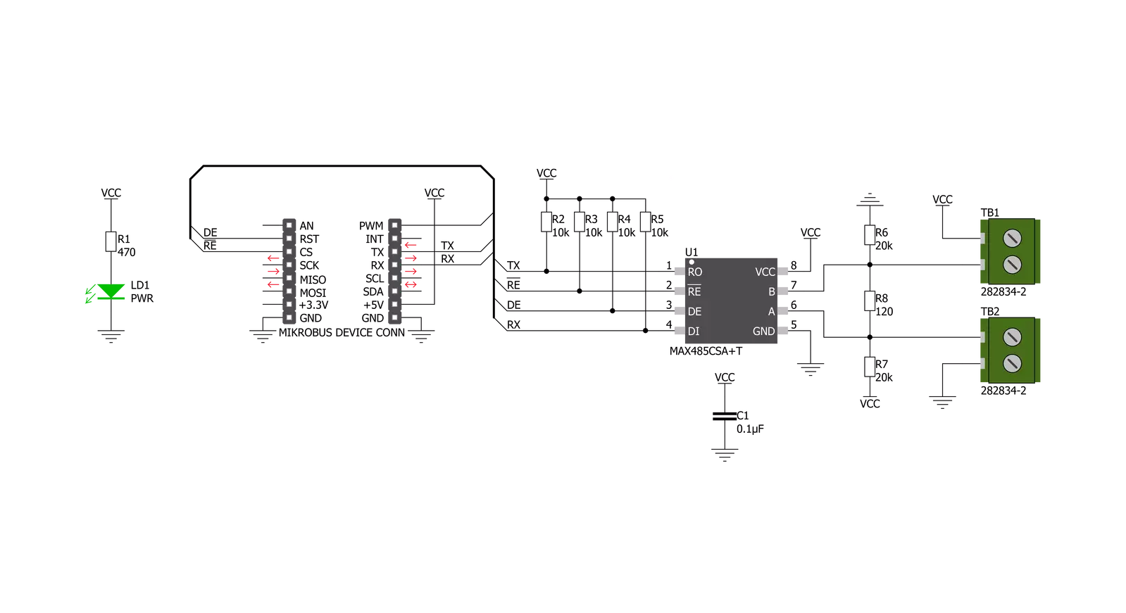
RS485 5 Click 基于 Analog Devices 的 MAX485,这是一款用于 RS-485 和 RS-422 通信的低功耗、速率限制的收发器,当未加载或完全加载且驱动器禁用时,其供电电流在 120µA 和 500µA 之间。所有部件都从单一的 5V 电源供电。驱动器具有短路电流限制,并通过热关断电路保护过度功耗,将驱动器输出置于高阻状态。接收器输入具有失效保护功能,确保如果输入开路,输出为逻辑高。MAX485 的转换速率没有限制,允许其以高达 2.5Mbps 的速度进行半双工通
信。通常,最大传输速度由总线长度决定,较长的总线线会导致较低的传输速度。RS485/422 线路应在其特性阻抗的两端终止,并且主线的分支长度应尽可能短,以最小化反射。RS-485/RS-422 标准涵盖最长 1220 米(4000 英尺)的线路长度。两种机制防止故障或总线争用引起的过大输出电流和功耗。输出级的折返电流限制在整个共模电压范围内提供对短路的即时保护。此外,如果温度过高,热关断电路将强制驱动器输出进入高阻态。板上有两个 2 极螺丝端子
(+、B、A、-)用于连接 RS422/485 总线双绞线电缆,以及 GND 和 VCC。标记为“A”和“B”的端子输入用于连接总线线。GND 和 VCC 导轨可用于为另一个节点提供电源。请注意,VCC 端子直接连接到 mikroBUS™ 的 5V 导轨。此 Click 板™ 仅能在 5V 逻辑电压水平下工作。在使用不同逻辑电平的 MCU 之前,必须进行适当的逻辑电压电平转换。此外,它还配备了一个包含功能和示例代码的库,可用作进一步开发的参考。


功能概述
开发板
Nucleo 32开发板搭载STM32F031K6 MCU,提供了一种经济且灵活的平台,适用于使用32引脚封装的STM32微控制器进行实验。该开发板具有Arduino™ Nano连接性,便于通过专用扩展板进行功能扩展,并且支持mbed,使其能够无缝集成在线资源。板载集成
ST-LINK/V2-1调试器/编程器,支持通过USB重新枚举,提供三种接口:虚拟串口(Virtual Com port)、大容量存储和调试端口。该开发板的电源供应灵活,可通过USB VBUS或外部电源供电。此外,还配备了三个LED指示灯(LD1用于USB通信,LD2用于电源
指示,LD3为用户可控LED)和一个复位按钮。STM32 Nucleo-32开发板支持多种集成开发环境(IDEs),如IAR™、Keil®和基于GCC的IDE(如AC6 SW4STM32),使其成为开发人员的多功能工具。

微控制器概述
MCU卡片 / MCU

建筑
ARM Cortex-M0
MCU 内存 (KB)
32
硅供应商
STMicroelectronics
引脚数
32
RAM (字节)
4096
你完善了我!
配件
Click Shield for Nucleo-32是扩展您的开发板功能的理想选择,专为STM32 Nucleo-32引脚布局设计。Click Shield for Nucleo-32提供了两个mikroBUS™插座,可以添加来自我们不断增长的Click板™系列中的任何功能。从传感器和WiFi收发器到电机控制和音频放大器,我们应有尽有。Click Shield for Nucleo-32与STM32 Nucleo-32开发板兼容,为用户提供了一种经济且灵活的方式,使用任何STM32微控制器快速创建原型,并尝试各种性能、功耗和功能的组合。STM32 Nucleo-32开发板无需任何独立的探针,因为它集成了ST-LINK/V2-1调试器/编程器,并随附STM32全面的软件HAL库和各种打包的软件示例。这个开发平台为用户提供了一种简便且通用的方式,将STM32 Nucleo-32兼容开发板与他们喜欢的Click板™结合,应用于即将开展的项目中。

使用的MCU引脚
mikroBUS™映射器
“仔细看看!”
Click board™ 原理图
一步一步来
项目组装

从选择您的开发板和Click板™开始。以Nucleo 32 with STM32F031K6 MCU作为您的开发板开始。


实时跟踪您的结果
应用程序输出
1. 应用程序输出 - 在调试模式下,“应用程序输出”窗口支持实时数据监控,直接提供执行结果的可视化。请按照提供的教程正确配置环境,以确保数据正确显示。

2. UART 终端 - 使用UART Terminal通过USB to UART converter监视数据传输,实现Click board™与开发系统之间的直接通信。请根据项目需求配置波特率和其他串行设置,以确保正常运行。有关分步设置说明,请参考提供的教程。

3. Plot 输出 - Plot功能提供了一种强大的方式来可视化实时传感器数据,使趋势分析、调试和多个数据点的对比变得更加直观。要正确设置,请按照提供的教程,其中包含使用Plot功能显示Click board™读数的分步示例。在代码中使用Plot功能时,请使用以下函数:plot(insert_graph_name, variable_name);。这是一个通用格式,用户需要将“insert_graph_name”替换为实际图表名称,并将“variable_name”替换为要显示的参数。

软件支持
库描述
该库包含 RS485 5 Click 驱动程序的 API。
关键功能:
rs4855_generic_write- 通用写入功能。rs4855_set_de_state- 设置 DE 引脚为高电平或低电平状态。rs4855_set_re_state- 设置 RE 引脚为高电平或低电平状态。
开源
代码示例
完整的应用程序代码和一个现成的项目可以通过NECTO Studio包管理器直接安装到NECTO Studio。 应用程序代码也可以在MIKROE的GitHub账户中找到。
/*!
 * \file
 * \brief Rs4855 Click example
 *
 * # Description
 * This example reads and processes data from RS485 5 clicks.
 *
 * The demo application is composed of two sections :
 *
 * ## Application Init
 * Initializes the driver and enables the selected mode.
 *
 * ## Application Task
 * Depending on the selected mode, it reads all the received data or sends the desired message
 * every 2 seconds.
 *
 * ## Additional Function
 * - rs4855_process ( ) - The general process of collecting the received data.
 *
 * \author MikroE Team
 *
 */
// ------------------------------------------------------------------- INCLUDES

#include "board.h"
#include "log.h"
#include "rs4855.h"
#include "string.h"

#define PROCESS_RX_BUFFER_SIZE 500

#define TEXT_TO_SEND "MikroE\r\n"

// ------------------------------------------------------------------ VARIABLES

#define DEMO_APP_RECEIVER
// #define DEMO_APP_TRANSMITTER

static rs4855_t rs4855;
static log_t logger;

// ------------------------------------------------------- ADDITIONAL FUNCTIONS

static void rs4855_process ( void )
{
    int32_t rsp_size;

    char uart_rx_buffer[ PROCESS_RX_BUFFER_SIZE ] = { 0 };
    uint8_t check_buf_cnt;

    rsp_size = rs4855_generic_read( &rs4855, uart_rx_buffer, PROCESS_RX_BUFFER_SIZE );

    if ( rsp_size >= strlen( TEXT_TO_SEND ) )
    {
        log_printf( &logger, "Received data: " );

        for ( check_buf_cnt = 0; check_buf_cnt < rsp_size; check_buf_cnt++ )
        {
            log_printf( &logger, "%c", uart_rx_buffer[ check_buf_cnt ] );
        }
    }
    Delay_ms ( 100 );
}

// ------------------------------------------------------ APPLICATION FUNCTIONS

void application_init ( void )
{
    log_cfg_t log_cfg;
    rs4855_cfg_t cfg;

    /**
     * Logger initialization.
     * Default baud rate: 115200
     * Default log level: LOG_LEVEL_DEBUG
     * @note If USB_UART_RX and USB_UART_TX
     * are defined as HAL_PIN_NC, you will
     * need to define them manually for log to work.
     * See @b LOG_MAP_USB_UART macro definition for detailed explanation.
     */
    LOG_MAP_USB_UART( log_cfg );
    log_init( &logger, &log_cfg );
    log_info( &logger, "---- Application Init ----" );

    //  Click initialization.

    rs4855_cfg_setup( &cfg );
    RS4855_MAP_MIKROBUS( cfg, MIKROBUS_1 );
    rs4855_init( &rs4855, &cfg );

    Delay_ms ( 100 );

#ifdef DEMO_APP_RECEIVER
    rs4855_set_re_state( &rs4855, RS4855_PIN_STATE_LOW );
    rs4855_set_de_state( &rs4855, RS4855_PIN_STATE_LOW );
    log_info( &logger, "---- Receiver mode ----" );
#endif
#ifdef DEMO_APP_TRANSMITTER
    rs4855_set_re_state( &rs4855, RS4855_PIN_STATE_HIGH );
    rs4855_set_de_state( &rs4855, RS4855_PIN_STATE_HIGH );
    log_info( &logger, "---- Transmitter mode ----" );
#endif
}

void application_task ( void )
{
#ifdef DEMO_APP_RECEIVER
    rs4855_process( );
#endif

#ifdef DEMO_APP_TRANSMITTER
    rs4855_generic_write( &rs4855, TEXT_TO_SEND, 8 );
    log_info( &logger, "---- Data sent ----" );
    Delay_ms ( 1000 );
    Delay_ms ( 1000 );
#endif
}

int main ( void )
{
    /* Do not remove this line or clock might not be set correctly. */
    #ifdef PREINIT_SUPPORTED
    preinit();
    #endif

    application_init( );

    for ( ; ; )
    {
        application_task( );
    }

    return 0;
}


// ------------------------------------------------------------------------ END


