通过基于INA260和STM32F031K6的数字VCP监控优化效率
您电流和功率卓越的数字指南!

已发布 10月 01, 2024
点击板
VCP Monitor Click
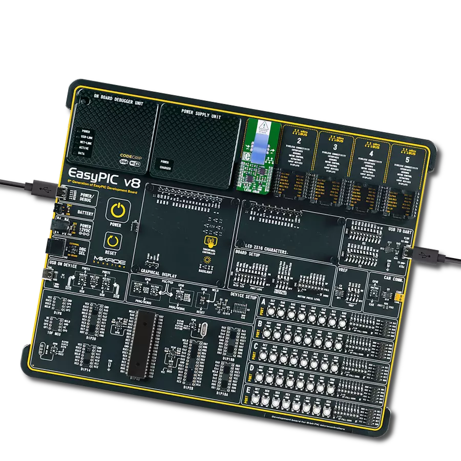
开发板
Nucleo 32 with STM32F031K6 MCU
编译器
NECTO Studio
微控制器单元
STM32F031K6
从实时诊断到性能优化,可能性无限。
A
A
硬件概览
它是如何工作的?
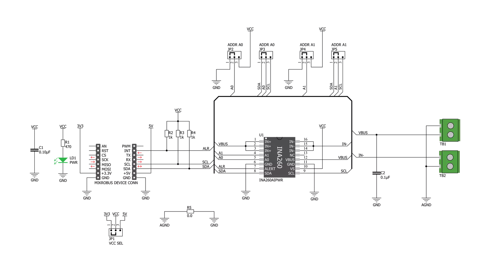
VCP Monitor Click 基于德州仪器的 INA260,这是一种功率监视解决方案,包括对电流、电压和功率的精确测量,漂移较小。电流传感电阻设计为 4 线连接电阻,通过力感应连接实现准确测量。INA260 内部校准,以确保电流传感电阻和放大器精确匹配。INA260 设备在电源总线上执行两个测量。LOAD 连接器上的电流测量通过测量跨越已知内部电流分流电阻的电压内部计算。该特性是一个物理电流分流电阻,可以承受高于连续处理限制的 15A 的电流水平,如果偶发情况,不会损坏电流传感电阻或电流传感放大器。SUPPLY 连接器上的电压测量是通过测量从外部 VBUS 引脚到地的电压计算的。所监测的电压
范围从 0V 到 36V。INA260 设备在电源总线上执行两个测量。LOAD 连接器上的电流测量通过测量跨越已知内部电流分流电阻的电压内部计算,SUPPLY 连接器上的电压测量是通过测量从外部 VBUS 引脚到地的电压计算的。VCP Monitor Click 兼容 I2C 通信协议。INA260 有两个从地址选择引脚,A0 和 A1。对于 I2C 从地址选择,VCP Monitor Click 有两个十字形跳线,第一个用于设置引脚 A0,第二个用于设置引脚 A1。一个十字形跳线有四个位置用于选择地址引脚,可以通过 SMD 0 欧姆电阻进行选择;地址引脚可以连接到 GND、VS、SCL 或 SDA 引脚。具有两个单独跳线的 VCP Monitor
Click 可以在 Click board™ 用户上设置所需的地址。INA260AIPWR 提供了 16 种不同 I2C 地址的可能性。INA260AIPWR 支持具有 ALERT 引脚的使用,该引脚连接到 mikroBUS™ 上的 INT 引脚,在发生警报情况时中断正在进行的 MCU 例程。INT 引脚可以编程以响应用户定义的事件或转换准备好的通知。这个 Click board™ 可以使用 VCC SEL 跳线选择 3.3V 或 5V 逻辑电压电平操作。这样,既可以使用 3.3V 又可以使用 5V 能力的 MCU 正确使用通信线路。此外,这个 Click board™ 配备了一个包含易于使用函数和示例代码的库,可以用作进一步开发的参考。


功能概述
开发板
Nucleo 32开发板搭载STM32F031K6 MCU,提供了一种经济且灵活的平台,适用于使用32引脚封装的STM32微控制器进行实验。该开发板具有Arduino™ Nano连接性,便于通过专用扩展板进行功能扩展,并且支持mbed,使其能够无缝集成在线资源。板载集成
ST-LINK/V2-1调试器/编程器,支持通过USB重新枚举,提供三种接口:虚拟串口(Virtual Com port)、大容量存储和调试端口。该开发板的电源供应灵活,可通过USB VBUS或外部电源供电。此外,还配备了三个LED指示灯(LD1用于USB通信,LD2用于电源
指示,LD3为用户可控LED)和一个复位按钮。STM32 Nucleo-32开发板支持多种集成开发环境(IDEs),如IAR™、Keil®和基于GCC的IDE(如AC6 SW4STM32),使其成为开发人员的多功能工具。

微控制器概述
MCU卡片 / MCU

建筑
ARM Cortex-M0
MCU 内存 (KB)
32
硅供应商
STMicroelectronics
引脚数
32
RAM (字节)
4096
你完善了我!
配件
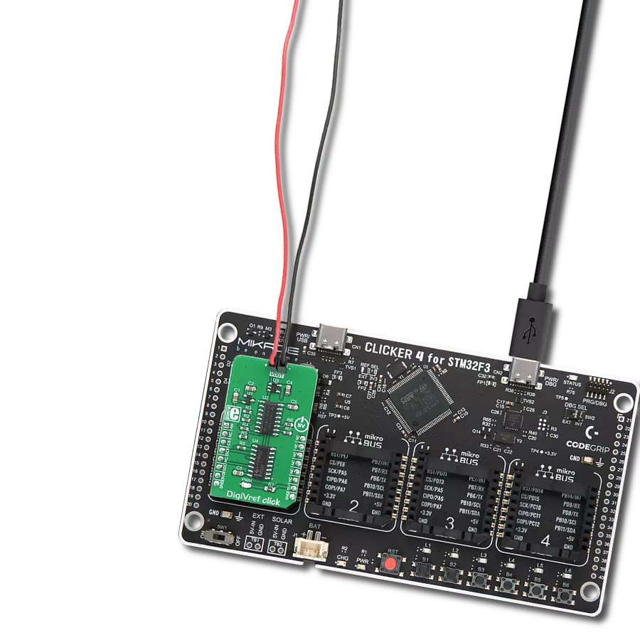
Click Shield for Nucleo-32是扩展您的开发板功能的理想选择,专为STM32 Nucleo-32引脚布局设计。Click Shield for Nucleo-32提供了两个mikroBUS™插座,可以添加来自我们不断增长的Click板™系列中的任何功能。从传感器和WiFi收发器到电机控制和音频放大器,我们应有尽有。Click Shield for Nucleo-32与STM32 Nucleo-32开发板兼容,为用户提供了一种经济且灵活的方式,使用任何STM32微控制器快速创建原型,并尝试各种性能、功耗和功能的组合。STM32 Nucleo-32开发板无需任何独立的探针,因为它集成了ST-LINK/V2-1调试器/编程器,并随附STM32全面的软件HAL库和各种打包的软件示例。这个开发平台为用户提供了一种简便且通用的方式,将STM32 Nucleo-32兼容开发板与他们喜欢的Click板™结合,应用于即将开展的项目中。

使用的MCU引脚
mikroBUS™映射器
“仔细看看!”
Click board™ 原理图
一步一步来
项目组装

从选择您的开发板和Click板™开始。以Nucleo 32 with STM32F031K6 MCU作为您的开发板开始。


实时跟踪您的结果
应用程序输出
1. 应用程序输出 - 在调试模式下,“应用程序输出”窗口支持实时数据监控,直接提供执行结果的可视化。请按照提供的教程正确配置环境,以确保数据正确显示。

2. UART 终端 - 使用UART Terminal通过USB to UART converter监视数据传输,实现Click board™与开发系统之间的直接通信。请根据项目需求配置波特率和其他串行设置,以确保正常运行。有关分步设置说明,请参考提供的教程。

3. Plot 输出 - Plot功能提供了一种强大的方式来可视化实时传感器数据,使趋势分析、调试和多个数据点的对比变得更加直观。要正确设置,请按照提供的教程,其中包含使用Plot功能显示Click board™读数的分步示例。在代码中使用Plot功能时,请使用以下函数:plot(insert_graph_name, variable_name);。这是一个通用格式,用户需要将“insert_graph_name”替换为实际图表名称,并将“variable_name”替换为要显示的参数。

软件支持
库描述
该库包含 VCP Monitor Click 驱动程序的 API。
关键功能:
vcpmonitor_get_current- 此函数读取以毫安 (mA) 表示的电流数据。vcpmonitor_get_power- 此函数读取以毫瓦 (mW) 表示的功率数据。vcpmonitor_get_voltage- 此函数读取以毫伏 (mV) 表示的电压数据。
开源
代码示例
完整的应用程序代码和一个现成的项目可以通过NECTO Studio包管理器直接安装到NECTO Studio。 应用程序代码也可以在MIKROE的GitHub账户中找到。
/*!
 * \file
 * \brief VCPmonitor Click example
 *
 * # Description
 * The VCP Monitor Click is add-on board power monitor system. This Click board is
 * based on precision digital current and power monitor with low-drift, integrated
 * precision shunt resistor.
 *
 * The demo application is composed of two sections :
 *
 * ## Application Init
 * Initiaizes the driver, and checks the communication by reading the device and manufacture IDs.
 * After that, performs the device default configuration.
 *
 * ## Application Task
 * Displays the voltage, current, and power measured by the sensor on the USB UART every 2 seconds.
 *
 * \author MikroE Team
 *
 */
// ------------------------------------------------------------------- INCLUDES

#include "board.h"
#include "log.h"
#include "vcpmonitor.h"

// ------------------------------------------------------------------ VARIABLES

static vcpmonitor_t vcpmonitor;
static log_t logger;
static uint16_t manufacture_id;
static uint16_t did_id;

// ------------------------------------------------------ APPLICATION FUNCTIONS

void application_init ( void )
{
    log_cfg_t log_cfg;
    vcpmonitor_cfg_t cfg;

    /**
     * Logger initialization.
     * Default baud rate: 115200
     * Default log level: LOG_LEVEL_DEBUG
     * @note If USB_UART_RX and USB_UART_TX
     * are defined as HAL_PIN_NC, you will
     * need to define them manually for log to work.
     * See @b LOG_MAP_USB_UART macro definition for detailed explanation.
     */
    LOG_MAP_USB_UART( log_cfg );
    log_init( &logger, &log_cfg );
    log_info( &logger, "---- Application Init ----" );

    vcpmonitor_cfg_setup( &cfg );
    VCPMONITOR_MAP_MIKROBUS( cfg, MIKROBUS_1 );
    vcpmonitor_init( &vcpmonitor, &cfg );

    if ( VCPMONITOR_OK == vcpmonitor_get_id_value( &vcpmonitor, &manufacture_id, &did_id ) )
    {
        log_printf( &logger, ">> Manufacture ID: 0x%.4X\r\n", manufacture_id );
        log_printf( &logger, ">> Device ID: 0x%.4X\r\n", did_id );
    }
    else
    {
        log_error( &logger, " WRONG ID READ! " );
        log_printf( &logger, "Please restart your system.\r\n" );
        for ( ; ; );
    }

    vcpmonitor_default_cfg(&vcpmonitor );
    Delay_ms ( 500 );
}

void application_task ( void )
{
    float current_data;
    float voltage_data;
    float power_data;

    current_data = vcpmonitor_get_current( &vcpmonitor );
    log_printf( &logger, ">> Current : %.2f mA\r\n", current_data );

    voltage_data = vcpmonitor_get_voltage( &vcpmonitor );
    log_printf( &logger, ">> Voltage : %.2f mV\r\n", voltage_data );

    power_data = vcpmonitor_get_power( &vcpmonitor );
    log_printf( &logger, ">> Power : %.2f mW\r\n", power_data );

    log_printf( &logger, "-------------------------------\r\n" );
    Delay_ms ( 1000 );
    Delay_ms ( 1000 );
}

int main ( void )
{
    /* Do not remove this line or clock might not be set correctly. */
    #ifdef PREINIT_SUPPORTED
    preinit();
    #endif

    application_init( );

    for ( ; ; )
    {
        application_task( );
    }

    return 0;
}


// ------------------------------------------------------------------------ END