使用TLE4966K和STM32G431RB打造无缝运动控制体验
方向检测如何改变您的DIY电子产品
已发布 11月 08, 2024
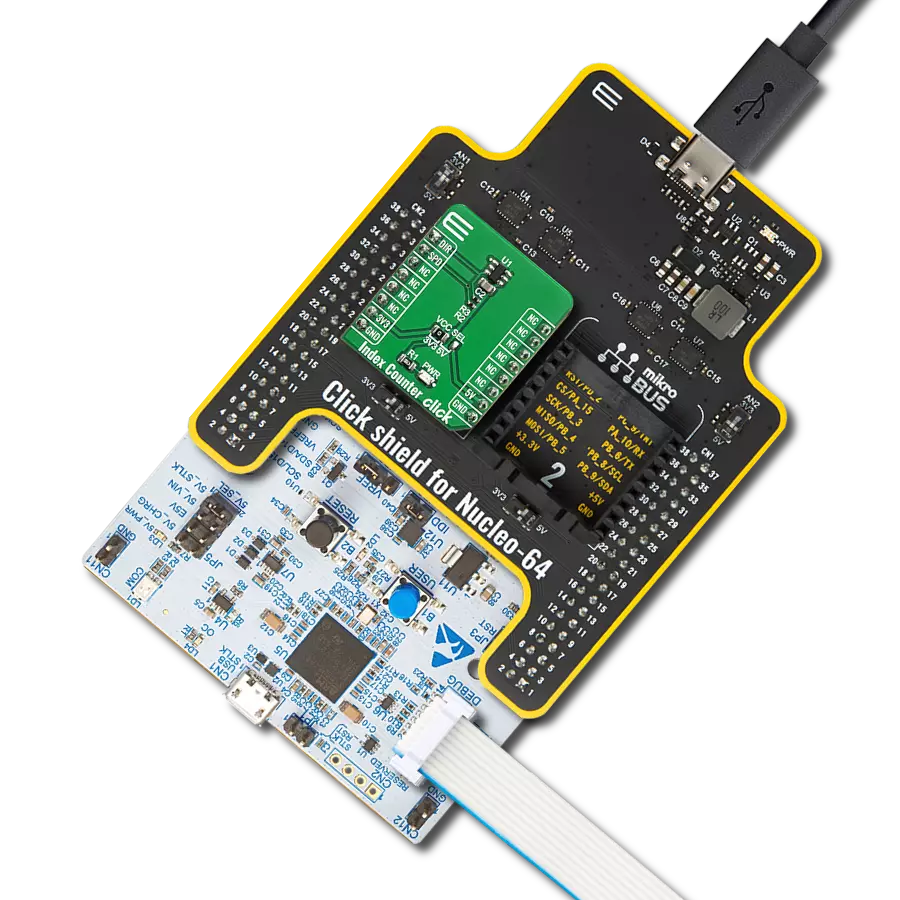
点击板
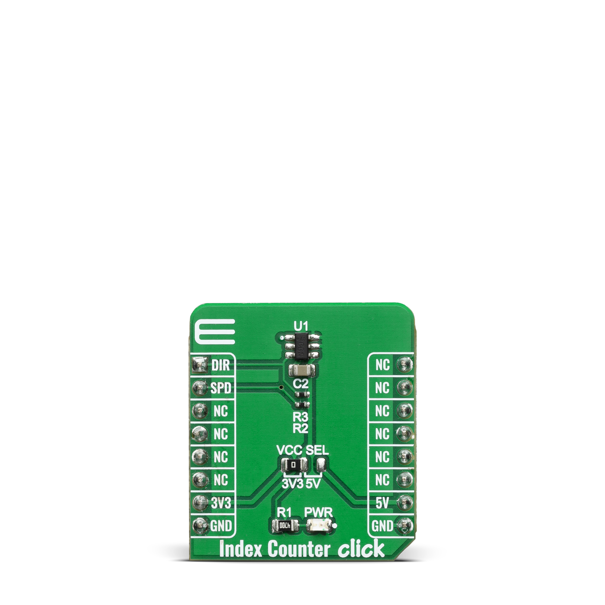
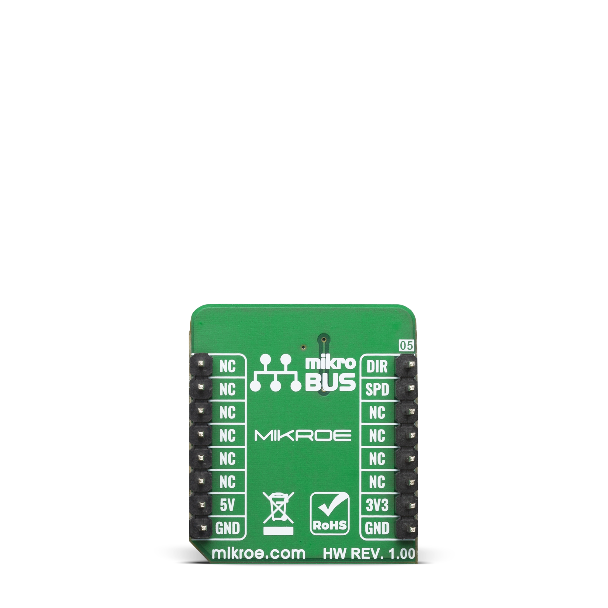
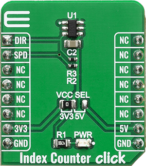
Index Counter Click
开发板
Nucleo 64 with STM32G431RB MCU
编译器
NECTO Studio
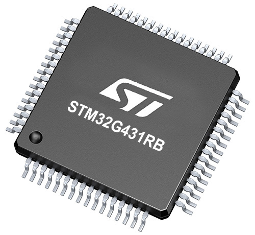
微控制器单元
STM32G431RB
释放您的创造力,开发突破性的解决方案,使用具有方向感应能力的高精度霍尔效应开关。
A
A
硬件概览
它是如何工作的?
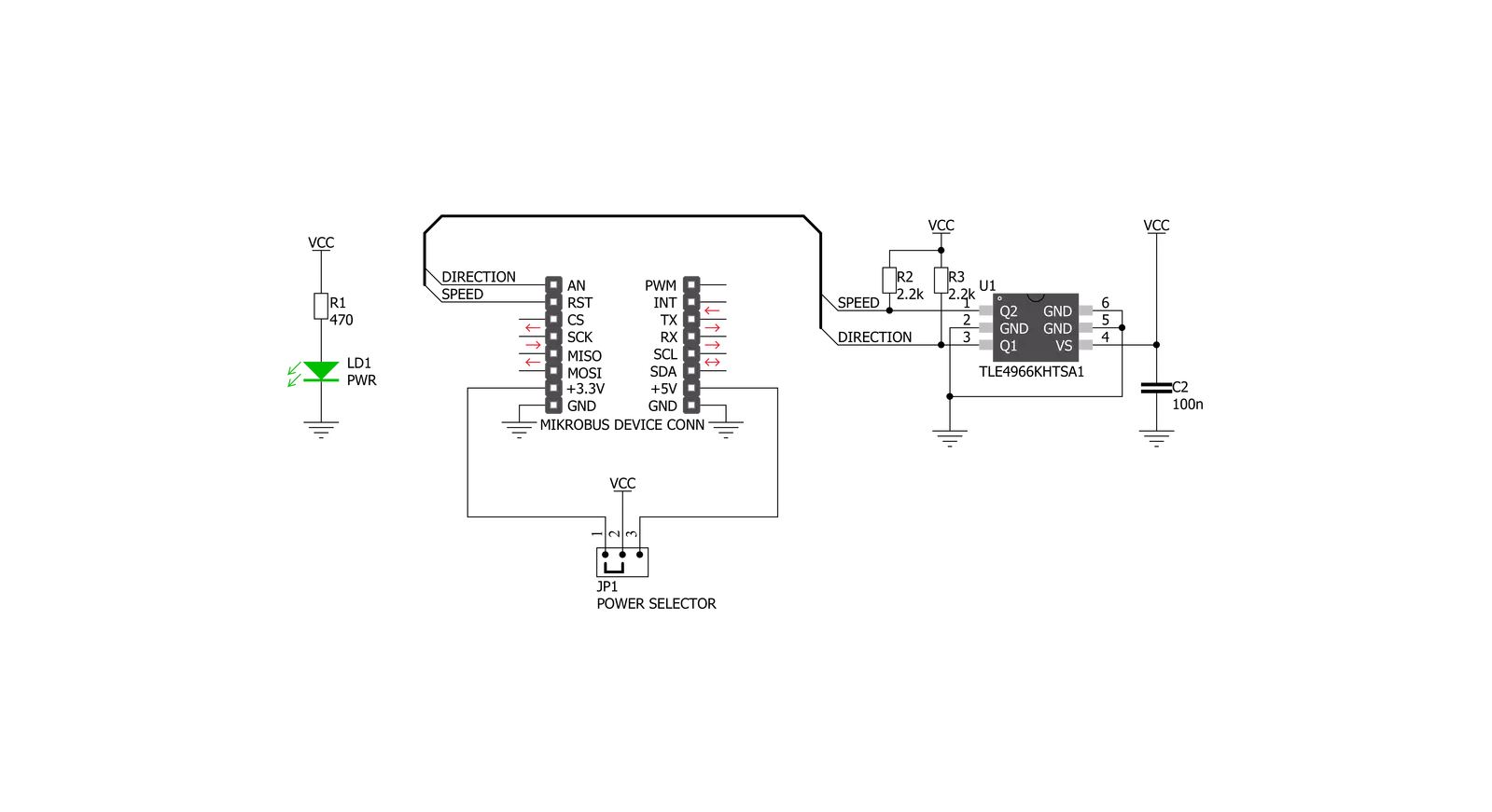
Index Counter Click基于Infineon的TLE4966K,这是一款具有反向电池保护的高灵敏度和高稳定性的磁性开关点传感器。该传感器具有许多特性,使其成为小型设计(如Index Counter Click板™)的完美解决方案。其中一个特点是其高度集成,允许最少的外部组件。TLE4966K提供出色的温度补偿能力,以在温度变化时保持输出稳定。它专为每个磁极对提供速度信号以及方向信息的高精度应用而设计。
TLE4966 Hall传感器具有两个集成和校准的传感器元件,用于检测方向和计数索引。这一特性消除了第二个传感器的需求,降低了工程和生产成本。使用一个传感器还提高了系统质量和可靠性。切换的双霍尔开关包括两个霍尔探头、偏置发生器、补偿电路、振荡器和输出晶体管。偏置发生器为霍尔探头和有源电路提供电流。补偿电路稳定温度行为并减少技术变化。有源误差补偿消除了信号阶段的
偏移以及由模塑和焊接过程以及封装中的其他热应力引起的对霍尔探头的机械应力影响。这种斩波技术与阈值发生器和比较器一起确保了高精度的磁开关点。该Click板™可以在3.3V或5V逻辑电压水平下工作,通过VCC SEL跳线选择。这种方式,3.3V和5V能力的MCU都可以正确使用通信线。此外,该Click板™配备了一个包含易于使用的功能和示例代码的库,可作为进一步开发的参考。
功能概述
开发板
Nucleo-64 搭载 STM32G431RB MCU 提供了一种经济高效且灵活的平台,供开发者探索新想法并原型设计他们的项目。该板利用 STM32 微控制器的多功能性,使用户能够为他们的项目选择最佳的性能与功耗平衡。它配备了 LQFP64 封装的 STM32 微控制器,并包含了如用户 LED(同时作为 ARDUINO® 信号)、用户和复位按钮,以及 32.768kHz 晶体振荡器用于精确的计时操作等基本组件。Nucleo-64 板设计考虑到扩展性和灵活性,它特有的 ARDUINO® Uno
V3 扩展连接器和 ST morpho 扩展引脚头,提供了对 STM32 I/O 的完全访问,以实现全面的项目整合。电源供应选项灵活,支持 ST-LINK USB VBUS 或外部电源,确保在各种开发环境中的适应性。该板还配备了一个具有 USB 重枚举功能的板载 ST-LINK 调试器/编程器,简化了编程和调试过程。此外,该板设计旨在简化高级开发,它的外部 SMPS 为 Vcore 逻辑供电提供高效支持,支持 USB 设备全速或 USB SNK/UFP 全速,并内置加密功能,提升了项目的功效
和安全性。通过外部 SMPS 实验的专用连接器、 用于 ST-LINK 的 USB 连接器以及 MIPI® 调试连接器,提供了更多的硬件接口和实验可能性。开发者将通过 STM32Cube MCU Package 提供的全面免费软件库和示例得到广泛支持。这些,加上与多种集成开发环境(IDE)的兼容性,包括 IAR Embedded Workbench®、MDK-ARM 和 STM32CubeIDE,确保了流畅且高效的开发体验,使用户能够充分利用 Nucleo-64 板在他们的项目中的能力。

微控制器概述
MCU卡片 / MCU
建筑
ARM Cortex-M4
MCU 内存 (KB)
128
硅供应商
STMicroelectronics
引脚数
64
RAM (字节)
32k
你完善了我!
配件
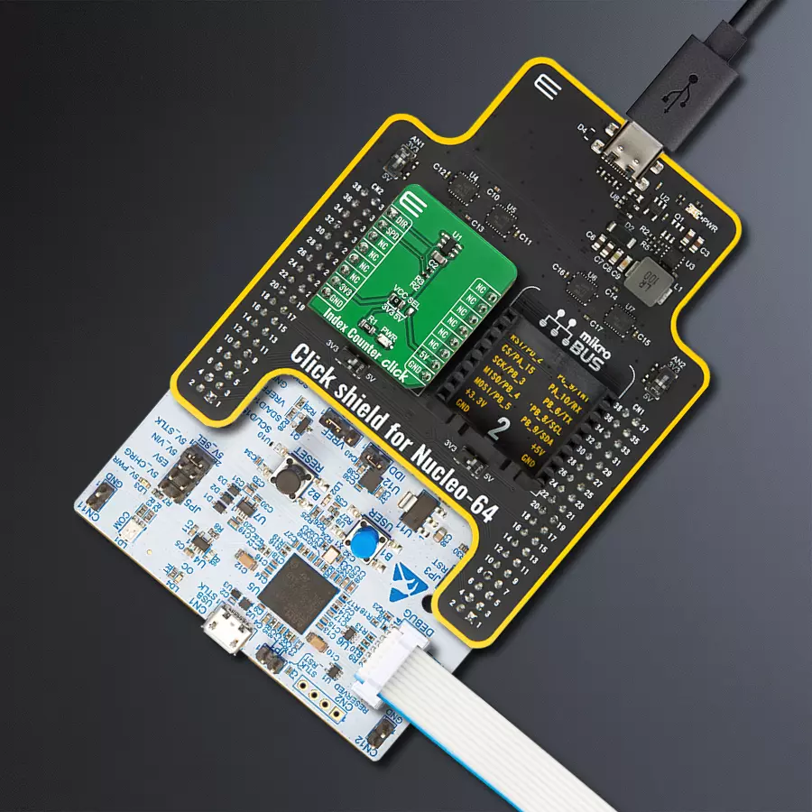
Click Shield for Nucleo-64 配备了两个专有的 mikroBUS™ 插座,使得所有的 Click board™ 设备都可以轻松地与 STM32 Nucleo-64 开发板连接。这样,Mikroe 允许其用户从不断增长的 Click boards™ 范围中添加任何功能,如 WiFi、GSM、GPS、蓝牙、ZigBee、环境传感器、LED、语音识别、电机控制、运动传感器等。您可以使用超过 1537 个 Click boards™,这些 Click boards™ 可以堆叠和集成。STM32 Nucleo-64 开发板基于 64 引脚封装的微控制器,采用 32 位 MCU,配备 ARM Cortex M4 处理器,运行速度为 84MHz,具有 512Kb Flash 和 96KB SRAM,分为两个区域,顶部区域代表 ST-Link/V2 调试器和编程器,而底部区域是一个实际的开发板。通过 USB 连接方便地控制和供电这些板子,以便直接对 Nucleo-64 开发板进行编程和高效调试,其中还需要额外的 USB 线连接到板子上的 USB 迷你接口。大多数 STM32 微控制器引脚都连接到了板子左右边缘的 IO 引脚上,然后连接到两个现有的 mikroBUS™ 插座上。该 Click Shield 还有几个开关,用于选择 mikroBUS™ 插座上模拟信号的逻辑电平和 mikroBUS™ 插座本身的逻辑电压电平。此外,用户还可以通过现有的双向电平转换器,使用任何 Click board™,无论 Click board™ 是否在 3.3V 或 5V 逻辑电压电平下运行。一旦将 STM32 Nucleo-64 开发板与我们的 Click Shield for Nucleo-64 连接,您就可以访问数百个工作于 3.3V 或 5V 逻辑电压电平的 Click boards™。

使用的MCU引脚
mikroBUS™映射器
“仔细看看!”
Click board™ 原理图
一步一步来
项目组装
从选择您的开发板和Click板™开始。以Nucleo 64 with STM32G431RB MCU作为您的开发板开始。


实时跟踪您的结果
应用程序输出
1. 应用程序输出 - 在调试模式下,“应用程序输出”窗口支持实时数据监控,直接提供执行结果的可视化。请按照提供的教程正确配置环境,以确保数据正确显示。

2. UART 终端 - 使用UART Terminal通过USB to UART converter监视数据传输,实现Click board™与开发系统之间的直接通信。请根据项目需求配置波特率和其他串行设置,以确保正常运行。有关分步设置说明,请参考提供的教程。

3. Plot 输出 - Plot功能提供了一种强大的方式来可视化实时传感器数据,使趋势分析、调试和多个数据点的对比变得更加直观。要正确设置,请按照提供的教程,其中包含使用Plot功能显示Click board™读数的分步示例。在代码中使用Plot功能时,请使用以下函数:plot(insert_graph_name, variable_name);。这是一个通用格式,用户需要将“insert_graph_name”替换为实际图表名称,并将“variable_name”替换为要显示的参数。

软件支持
库描述
该库包含 Index Counter Click 驱动程序的 API。
关键功能:
indexcounter_get_dir- 此功能返回方向DIR(AN)引脚的状态indexcounter_get_speed- 此功能返回速度SPD(RST)引脚的状态
开源
代码示例
完整的应用程序代码和一个现成的项目可以通过NECTO Studio包管理器直接安装到NECTO Studio。 应用程序代码也可以在MIKROE的GitHub账户中找到。
/*!
 * \file
 * \brief Index Counter Click example
 *
 * # Description
 * This application enables usage of Index counter Click board which can be used to measure rotational speed.
 *
 *
 * The demo application is composed of two sections :
 *
 * ## Application Init
 * Initilaziation of GPIO and write log.
 *
 * ## Application Task
 * This is an example which demonstrates the use of the Index Counter Click board.
 * This example shows the direction of movement, Rotations Per Minute ( RPM or speed )
 * of the three pairs of rotating poles positioned in the sensor operating range.
 * Results are being sent to the Usart Terminal where you can track their changes.
 *
 * *note:*
 * Additional Functions :
 *   - void log_display ( float rpm_val ) - The function displays all results
 *     and a float value with a comma with two decimal places.
 *
 * \author MikroE Team
 *
 */
// ------------------------------------------------------------------- INCLUDES

#include "board.h"
#include "log.h"
#include "indexcounter.h"

// ------------------------------------------------------------------ VARIABLES

static indexcounter_t indexcounter;
static log_t logger;

uint8_t dir_state;
uint8_t speed_state;
uint8_t enable_speed = INDEXCOUNTER_SPEED_ENABLE;
uint8_t n_pole_pairs = 3;
uint32_t time_cnt = 0;
uint32_t pulse_ms;
uint32_t start_timer = 1;
float speed_rpm;

// ------------------------------------------------------- ADDITIONAL FUNCTIONS

void log_display ( float rpm_val )
{
    uint16_t disp_float;

    disp_float = ( uint16_t ) rpm_val;

    log_printf( &logger, " Direction :" );

    if ( dir_state == 0 )
    {
        log_printf( &logger, " Forward \r\n" );
    }
    else
    {
        log_printf( &logger, " Reverse \r\n" );
    }

    log_printf( &logger, " Speed     : %d.", disp_float );

    disp_float = ( uint16_t ) ( rpm_val * 100 );

    log_printf( &logger, "%d rpm\r\n", disp_float );

    log_printf( &logger, " Time      : %ld  ms \r\n", time_cnt );

    log_printf ( &logger, "-----------------------" );
}

// ------------------------------------------------------ APPLICATION FUNCTIONS

void application_init ( void )
{
    log_cfg_t log_cfg;
    indexcounter_cfg_t cfg;

    /**
     * Logger initialization.
     * Default baud rate: 115200
     * Default log level: LOG_LEVEL_DEBUG
     * @note If USB_UART_RX and USB_UART_TX
     * are defined as HAL_PIN_NC, you will
     * need to define them manually for log to work.
     * See @b LOG_MAP_USB_UART macro definition for detailed explanation.
     */
    LOG_MAP_USB_UART( log_cfg );
    log_init( &logger, &log_cfg );
    log_info(&logger, "---- Application Init ----");

    //  Click initialization.

    indexcounter_cfg_setup( &cfg );
    INDEXCOUNTER_MAP_MIKROBUS( cfg, MIKROBUS_1 );
    indexcounter_init( &indexcounter, &cfg );
}

void application_task ( void )
{
    //  Task implementation.

    speed_state = indexcounter_get_speed( &indexcounter );
    dir_state = indexcounter_get_dir( &indexcounter );

    if ( enable_speed && speed_state )
    {
        pulse_ms = time_cnt - start_timer;
        start_timer = time_cnt;
        speed_rpm = INDEXCOUNTER_ONE_MIN_CONV_MS / ( pulse_ms * n_pole_pairs );
        enable_speed = INDEXCOUNTER_SPEED_DISABLE;

        log_display ( speed_rpm );
    }

    if ( ( !enable_speed ) && ( !speed_state ) )
    {
        enable_speed = INDEXCOUNTER_SPEED_ENABLE;
    }

    Delay_1ms();
    time_cnt++;
}

int main ( void )
{
    /* Do not remove this line or clock might not be set correctly. */
    #ifdef PREINIT_SUPPORTED
    preinit();
    #endif

    application_init( );

    for ( ; ; )
    {
        application_task( );
    }

    return 0;
}


// ------------------------------------------------------------------------ END


