使用MICRF220和STM32G431RB接收和处理RF信号
具有RSSI和静噪功能的ASK/OOK 315MHz RF接收器
已发布 11月 08, 2024
点击板
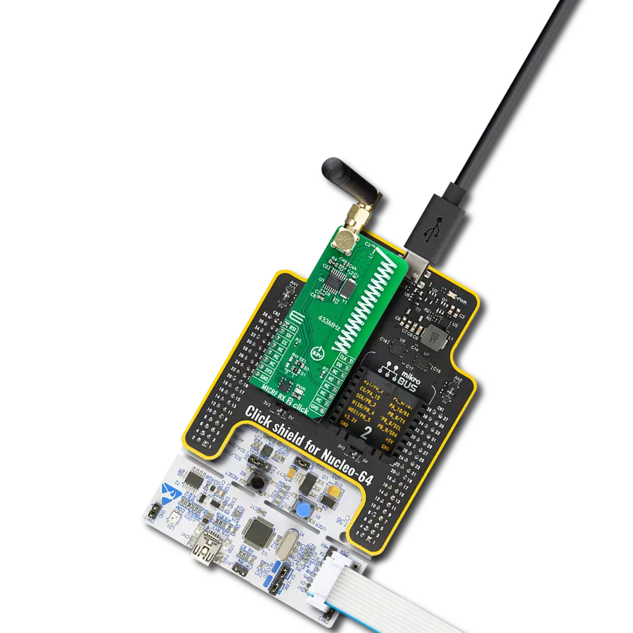
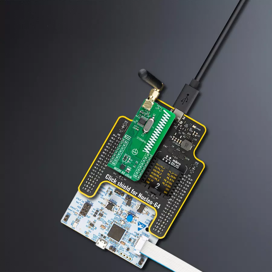
MICRF RX Click
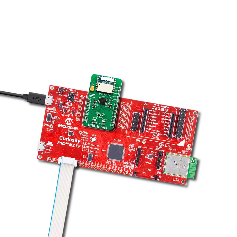
开发板
Nucleo 64 with STM32G431RB MCU
编译器
NECTO Studio
微控制器单元
STM32G431RB
开发解决方案,使各种设备的远程控制成为可能,例如家庭自动化系统或工业机械。
A
A
硬件概览
它是如何工作的?
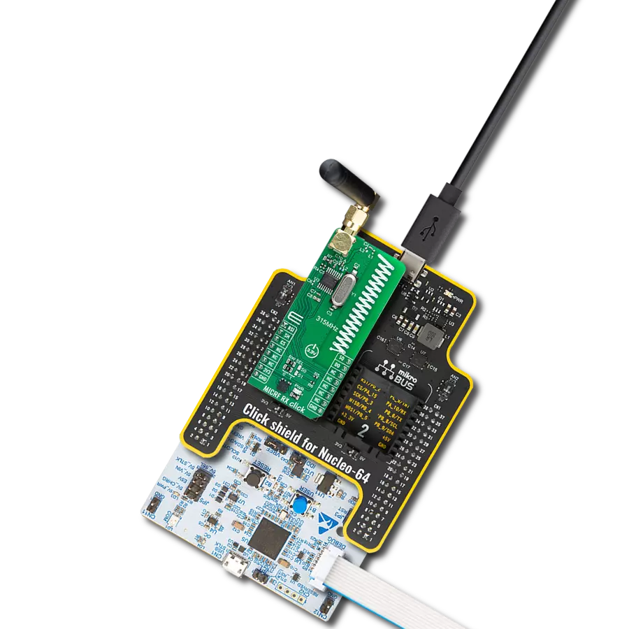
MICRF RX Click 基于来自Microchip的MICRF220,这是一款带有RSSI和静噪的ASK/OOK接收器。这款超外差、抗镜像 RF 接收器经过设计,只需一个晶体即可运行,在本例中是板载的9.81563MHz,并且只需要一组最少的外部元件。它适用于各种应用,例如低功耗远程无钥匙进入(RKE)、轮胎压力监测系统(TPMS)和远程操作系统。在性能方面,MICRF220 以-110dBm的灵敏度、1kbps和0.1%的比特错误率(BER)脱颖而出,并配备了四种可选择的解调器滤波器带宽,范围从1170Hz到
在9400Hz。通过将 BW SEL 跳线放置相应的位置(0或1),可以选择滤波器带宽,根据附带的 MICRF220 数据表中的真值表(Table 2.)选择相应的频率。此功能允许设备容纳高达14.4kbps的比特率(从1.8kbps到14.4kbps)。它在来自mikroBUS™电源轨的3.3V供电下运行,经过优化以进行315MHz操作,典型供电电流为4.3mA。此外,MICRF220 具有低功耗关机模式,通过 SH 引脚可控制,将供电电流降低到令人印象深刻的0.1µA。它还具有一个通过 SQ 引脚访问的静噪功能,可最小化 DO 引脚上的数据
输出活动,直到检测到有效比特而不影响接收机灵敏度。该板还集成了一个 RSI 引脚,用于指示接收信号强度。对于天线配置,该板允许使用专门调谐到315MHz的板载PCB天线或通过SMA连接器使用外部天线,通过调节SMA连接器附近位置 A 到位置 B 的电容器进行选择。此 Click board™ 只能使用3.3V逻辑电压级别。在使用具有不同逻辑电平的MCU之前,板必须执行适当的逻辑电压级别转换。此外,它配备了一个包含函数和示例代码的库,可用作进一步开发的参考。

功能概述
开发板
Nucleo-64 搭载 STM32G431RB MCU 提供了一种经济高效且灵活的平台,供开发者探索新想法并原型设计他们的项目。该板利用 STM32 微控制器的多功能性,使用户能够为他们的项目选择最佳的性能与功耗平衡。它配备了 LQFP64 封装的 STM32 微控制器,并包含了如用户 LED(同时作为 ARDUINO® 信号)、用户和复位按钮,以及 32.768kHz 晶体振荡器用于精确的计时操作等基本组件。Nucleo-64 板设计考虑到扩展性和灵活性,它特有的 ARDUINO® Uno
V3 扩展连接器和 ST morpho 扩展引脚头,提供了对 STM32 I/O 的完全访问,以实现全面的项目整合。电源供应选项灵活,支持 ST-LINK USB VBUS 或外部电源,确保在各种开发环境中的适应性。该板还配备了一个具有 USB 重枚举功能的板载 ST-LINK 调试器/编程器,简化了编程和调试过程。此外,该板设计旨在简化高级开发,它的外部 SMPS 为 Vcore 逻辑供电提供高效支持,支持 USB 设备全速或 USB SNK/UFP 全速,并内置加密功能,提升了项目的功效
和安全性。通过外部 SMPS 实验的专用连接器、 用于 ST-LINK 的 USB 连接器以及 MIPI® 调试连接器,提供了更多的硬件接口和实验可能性。开发者将通过 STM32Cube MCU Package 提供的全面免费软件库和示例得到广泛支持。这些,加上与多种集成开发环境(IDE)的兼容性,包括 IAR Embedded Workbench®、MDK-ARM 和 STM32CubeIDE,确保了流畅且高效的开发体验,使用户能够充分利用 Nucleo-64 板在他们的项目中的能力。

微控制器概述
MCU卡片 / MCU
建筑
ARM Cortex-M4
MCU 内存 (KB)
128
硅供应商
STMicroelectronics
引脚数
64
RAM (字节)
32k
你完善了我!
配件
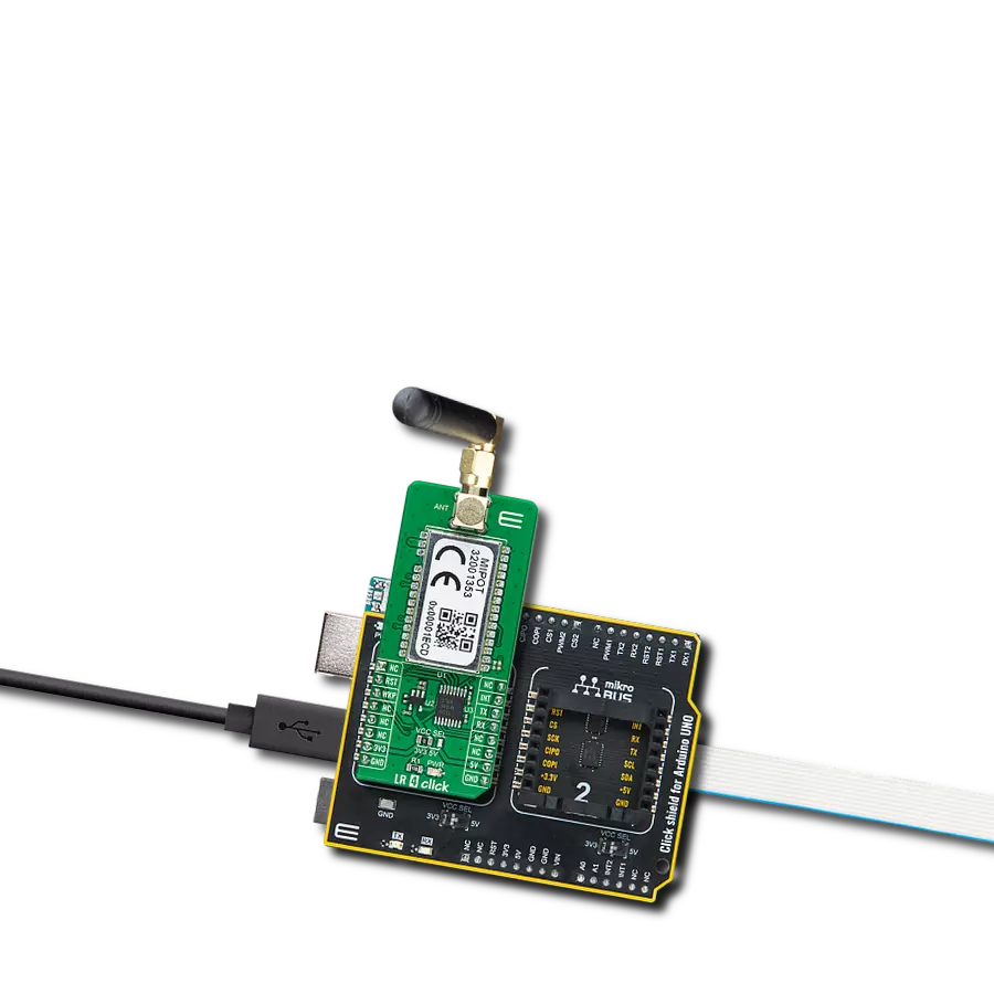
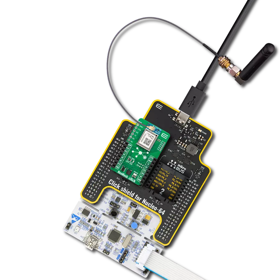
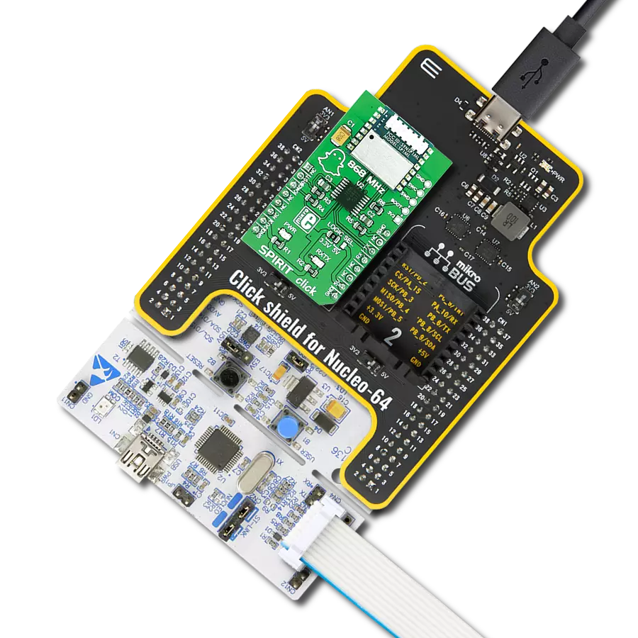
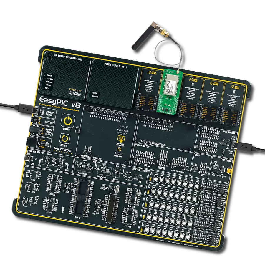
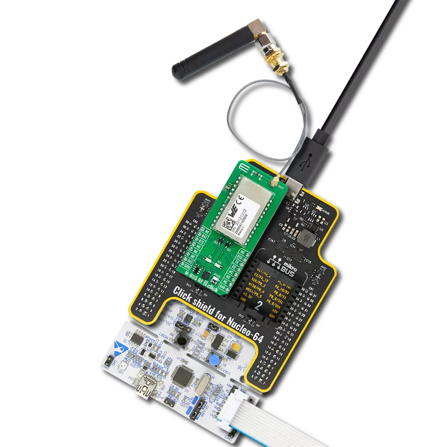
Click Shield for Nucleo-64 配备了两个专有的 mikroBUS™ 插座,使得所有的 Click board™ 设备都可以轻松地与 STM32 Nucleo-64 开发板连接。这样,Mikroe 允许其用户从不断增长的 Click boards™ 范围中添加任何功能,如 WiFi、GSM、GPS、蓝牙、ZigBee、环境传感器、LED、语音识别、电机控制、运动传感器等。您可以使用超过 1537 个 Click boards™,这些 Click boards™ 可以堆叠和集成。STM32 Nucleo-64 开发板基于 64 引脚封装的微控制器,采用 32 位 MCU,配备 ARM Cortex M4 处理器,运行速度为 84MHz,具有 512Kb Flash 和 96KB SRAM,分为两个区域,顶部区域代表 ST-Link/V2 调试器和编程器,而底部区域是一个实际的开发板。通过 USB 连接方便地控制和供电这些板子,以便直接对 Nucleo-64 开发板进行编程和高效调试,其中还需要额外的 USB 线连接到板子上的 USB 迷你接口。大多数 STM32 微控制器引脚都连接到了板子左右边缘的 IO 引脚上,然后连接到两个现有的 mikroBUS™ 插座上。该 Click Shield 还有几个开关,用于选择 mikroBUS™ 插座上模拟信号的逻辑电平和 mikroBUS™ 插座本身的逻辑电压电平。此外,用户还可以通过现有的双向电平转换器,使用任何 Click board™,无论 Click board™ 是否在 3.3V 或 5V 逻辑电压电平下运行。一旦将 STM32 Nucleo-64 开发板与我们的 Click Shield for Nucleo-64 连接,您就可以访问数百个工作于 3.3V 或 5V 逻辑电压电平的 Click boards™。

这款右角433MHz橡胶天线具有433MHz频率范围,确保在此频谱内实现最佳性能。其50欧姆阻抗有助于实现高效的信号传输。天线的垂直极化增强了特定方向的信号接收。具有1.5dB增益,可以在一定程度上提高信号强度。该天线可承受最大50W的输入功率,适用于各种应用。其紧凑的50mm长度使其空间要求最小化。配备SMA公头连接器,可轻松与兼容设备连接。这款天线是无线通信需求的灵活解决方案,尤其在垂直极化至关重要时。

使用的MCU引脚
mikroBUS™映射器
“仔细看看!”
Click board™ 原理图

一步一步来
项目组装
从选择您的开发板和Click板™开始。以Nucleo 64 with STM32G431RB MCU作为您的开发板开始。


软件支持
库描述
该库包含 MICRF RX Click 驱动程序的 API。
关键功能:
micrfrx_enable_device- 此函数通过将SHD引脚设置为低逻辑状态来启用设备。micrfrx_wait_ready- 此函数等待所有训练字节到达,表示数据已准备好。micrfrx_read_packet- 此函数仅在成功接收MICRFRX_PREAMBLE字节时读取数据包并将其存储在packet_buf中。
开源
代码示例
完整的应用程序代码和一个现成的项目可以通过NECTO Studio包管理器直接安装到NECTO Studio。 应用程序代码也可以在MIKROE的GitHub账户中找到。
/*!
 * @file main.c
 * @brief MICRF RX Click Example.
 *
 * # Description
 * This example demonstrates the use of MICRF RX Click board by reading and parsing
 * packet messages received from the transmitter.
 *
 * The demo application is composed of two sections :
 *
 * ## Application Init
 * Initializes the driver and enables the device and squelch mode.
 *
 * ## Application Task
 * Waits for a data ready indication, then reads all packet data, verifies the CRC
 * bytes in a packet, and displays its data as well as the RSSI value on the USB UART.
 *
 * @note
 * The MICRF TX Click board is a compatible transmitter for the MICRF RX Click.
 * Here are a few steps for troubleshooting if you are experiencing issues running
 * this example:
 *  - Make sure the MICRF TX Click is set to ASK mode with on-board jumpers.
 *  - Check the MCU clock configuration, use an external oscillator instead of the MCU's
 * internal one for better accuracy on manchester data rate delay.
 *  - Measure the actual data rate on the data line and adjust the MICRFRX_MAN_BIT_LEN_US
 * value accordingly.
 *
 * @author Stefan Filipovic
 *
 */

#include "board.h"
#include "log.h"
#include "micrfrx.h"

#define MICRFRX_PREAMBLE    0x5AA5  /**< Packet preamble word. */

static micrfrx_t micrfrx;   /**< MICRF RX Click driver object. */
static log_t logger;        /**< Logger object. */
static uint8_t packet_buf[ MICRFRX_MAX_DATA_LEN + 5 ] = { 0 };  /**< Packet buffer. */

/**
 * @brief MICRF RX wait ready function.
 * @details This function waits for all training bytes to arrive which indicates data ready.
 * @param[in] ctx : Click context object.
 * See #micrfrx_t object definition for detailed explanation.
 * @return None.
 * @note None.
 */
static void micrfrx_wait_ready ( micrfrx_t *ctx );

/**
 * @brief MICRF RX read packet function.
 * @details This function reads data packet and stores it in a packet_buf only if
 * the MICRFRX_PREAMBLE bytes are received successfully.
 * @param[in] ctx : Click context object.
 * See #micrfrx_t object definition for detailed explanation.
 * @return Number of data bytes stored in a packet_buf.
 * @note The expected packet format is as follows (MSB first, manchester IEEE 802.3):
 * TRAINING_BYTES (at least two bytes of 0xAA), PREABMLE, LEN, DATA_IN, CRC16 (calculated
 * from whole packet excluding training bytes). Training bytes are excluded from packet_buf.
 * This function must be called immediately after calling micrfrx_wait_ready.
 */
static uint8_t micrfrx_read_packet ( micrfrx_t *ctx );

/**
 * @brief Reflect bits.
 * @details This function reflects a desired number of bits in data.
 * @return Reflected data.
 * @note None.
 */
static uint16_t micrfrx_reflect_bits( uint16_t data_in, uint8_t len );

/**
 * @brief CRC-16/MAXIM calculation for CRC16 function.
 * @details This function calculates CRC16 with parameteres:
 * @li @c  Width 16 bit
 * @li @c  Polynomial 0x8005 ( x16 + x15 + x2 + x0 )
 * @li @c  Initialization 0x0000
 * @li @c  Reflect input True
 * @li @c  Reflect output True
 * @li @c  Final Xor 0xFFFF
 * @li @c  Example { 69, 00 } - 0xAFD1
 * @param[in] data_buf : Array of bytes to calculate crc from.
 * @param[in] len : Number of bytes to calculate crc from.
 * @return Calculated CRC.
 * @note None.
 */
static uint16_t micrfrx_calculate_crc16 ( uint8_t *data_buf, uint16_t len );

void application_init ( void )
{
    log_cfg_t log_cfg;  /**< Logger config object. */
    micrfrx_cfg_t micrfrx_cfg;  /**< Click config object. */

    /**
     * Logger initialization.
     * Default baud rate: 115200
     * Default log level: LOG_LEVEL_DEBUG
     * @note If USB_UART_RX and USB_UART_TX
     * are defined as HAL_PIN_NC, you will
     * need to define them manually for log to work.
     * See @b LOG_MAP_USB_UART macro definition for detailed explanation.
     */
    LOG_MAP_USB_UART( log_cfg );
    log_init( &logger, &log_cfg );
    log_info( &logger, " Application Init " );

    // Click initialization.
    micrfrx_cfg_setup( &micrfrx_cfg );
    MICRFRX_MAP_MIKROBUS( micrfrx_cfg, MIKROBUS_1 );
    if ( DIGITAL_OUT_UNSUPPORTED_PIN == micrfrx_init( &micrfrx, &micrfrx_cfg ) )
    {
        log_error( &logger, " Communication init." );
        for ( ; ; );
    }

    micrfrx_enable_squelch ( &micrfrx );
    micrfrx_enable_device ( &micrfrx );

    log_info( &logger, " Application Task " );
}

void application_task ( void )
{
    static float rssi_v = 0;
    static uint8_t packet_len = 0;
    static uint8_t msg_cnt = 0;
    static uint16_t crc = 0;

    log_printf( &logger, "\r\n Waiting for data ready...\r\n" );
    micrfrx_wait_ready ( &micrfrx );
    packet_len = micrfrx_read_packet ( &micrfrx );
    if ( packet_len )
    {
        micrfrx_read_rssi_voltage ( &micrfrx, &rssi_v );
        crc = ( ( uint16_t ) packet_buf[ packet_len - 2 ] << 8 ) | packet_buf[ packet_len - 1 ];
        if ( crc == micrfrx_calculate_crc16 ( packet_buf, packet_len - 2 ) )
        {
            log_printf( &logger, " Received message: " );
            for ( msg_cnt = 0; msg_cnt < packet_buf[ 2 ]; msg_cnt++ )
            {
                log_printf( &logger, "%c", ( uint16_t ) packet_buf[ msg_cnt + 3 ] );
            }
            log_printf( &logger, "\r\n RSSI: %.1f dBm\r\n", MICRFRX_RSSI_V_TO_DBM ( rssi_v ) );
        }
    }
    Delay_ms ( 100 );
}

int main ( void )
{
    /* Do not remove this line or clock might not be set correctly. */
    #ifdef PREINIT_SUPPORTED
    preinit();
    #endif

    application_init( );

    for ( ; ; )
    {
        application_task( );
    }

    return 0;
}

static void micrfrx_wait_ready ( micrfrx_t *ctx )
{
    uint16_t time_cnt = 0;
    uint16_t training_high_cnt = 0;
    uint16_t training_low_cnt = 0;
    // Loop until at least two 0xAA bytes of training data is detected
    for ( ; ; )
    {
        // Measure time in steps of MICRFRX_MAN_BIT_LEN_US / 40 for high signal
        for ( time_cnt = 0; micrfrx_get_data_pin ( ctx ); time_cnt++ )
        {
            Delay_us ( MICRFRX_MAN_BIT_LEN_US / 40 );
        }
        if ( time_cnt > 30 )
        {
            // Increment training_high_cnt if signal width is at least 75% of MICRFRX_MAN_BIT_LEN_US
            training_high_cnt++;
        }
        else
        {
            // Reset counters if any invalid signal is detected
            training_high_cnt = 0;
            training_low_cnt = 0;
        }

        // Measure time in steps of MICRFRX_MAN_BIT_LEN_US / 40 for low signal
        for ( time_cnt = 0; ( training_high_cnt > 0 ) && !micrfrx_get_data_pin ( ctx ); time_cnt++ )
        {
            Delay_us ( MICRFRX_MAN_BIT_LEN_US / 40 );
        }
        if ( time_cnt > 30 )
        {
            // Increment training_low_cnt if signal width is at least 75% of MICRFRX_MAN_BIT_LEN_US
            training_low_cnt++;
        }
        else if ( ( training_high_cnt >= 8 ) && ( training_high_cnt == ( training_low_cnt + 1 ) ) )
        {
            // At least two 0xAA bytes are detected ending with shorter low signal, so break the loop here.
            // Waiting for 12.5% of MICRFRX_MAN_BIT_LEN_US as an offset for packet reading.
            Delay_us ( MICRFRX_MAN_BIT_LEN_US / 8 );
            break;
        }
    }
}

static uint8_t micrfrx_read_packet ( micrfrx_t *ctx )
{
    uint8_t byte_cnt = 0;
    uint8_t bit_cnt = 0;
    // Loop until all data bytes are received or a bad PREAMBLE word is detected
    for ( ; ; )
    {
        if ( !micrfrx_get_data_pin ( ctx ) )
        {
            // Store data in packet_buf in manchester IEEE 802.3 format, MSB first
            packet_buf[ byte_cnt ] |= ( 0x80 >> bit_cnt );
        }

        if ( 8 == ++bit_cnt )
        {
            // Reset bit counter and increment byte counter if 8 bits are received
            bit_cnt = 0;
            byte_cnt++;
        }

        if ( 2 == byte_cnt )
        {
            // Two bytes are received, check PREAMBLE word
            if ( MICRFRX_PREAMBLE != ( ( ( uint16_t ) packet_buf[ 0 ] << 8 ) | packet_buf[ 1 ] ) )
            {
                byte_cnt = 0;
                break;
            }
        }
        else if ( ( packet_buf[ 2 ] + 5 ) == byte_cnt )
        {
            // Break the loop if all packet data are received (PREAMBLE + DATA_LEN + DATA + CRC)
            break;
        }

        // Move to the next manchester clock high state by delaying for MICRFRX_MAN_BIT_LEN_US
        Delay_us ( MICRFRX_MAN_BIT_LEN_US );
    }
    return byte_cnt;
}

static uint16_t micrfrx_reflect_bits( uint16_t data_in, uint8_t len )
{
    uint16_t data_out = 0;
    for ( uint16_t cnt = 0; cnt < len; cnt++ )
    {
        data_out |= ( ( data_in >> cnt ) & 1 ) << ( len - cnt - 1 );
    }
    return data_out;
}

static uint16_t micrfrx_calculate_crc16( uint8_t *data_buf, uint16_t len )
{
    uint16_t crc16 = 0x0000;
    for ( uint16_t cnt = 0; cnt < len; cnt++ )
    {
        crc16 ^= ( micrfrx_reflect_bits( data_buf[ cnt ], 8 ) << 8 );
        for ( uint8_t bit_cnt = 0; bit_cnt < 8; bit_cnt++ )
        {
            if ( crc16 & 0x8000 )
            {
                crc16 = ( crc16 << 1 ) ^ 0x8005;
            }
            else
            {
                crc16 <<= 1;
            }
        }
    }
    return micrfrx_reflect_bits( crc16, 16 ) ^ 0xFFFF;
}

// ------------------------------------------------------------------------ END
额外支持
资源
类别:1GHz以下收发器