Experience precise motor control with Toshiba's TB62262FTG and PIC18LF45K40
The motor control solution that won't drive you crazy
Published Nov 01, 2023
Click board™
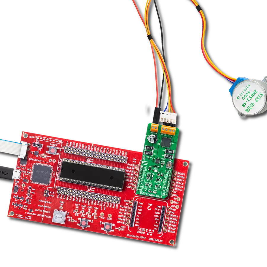
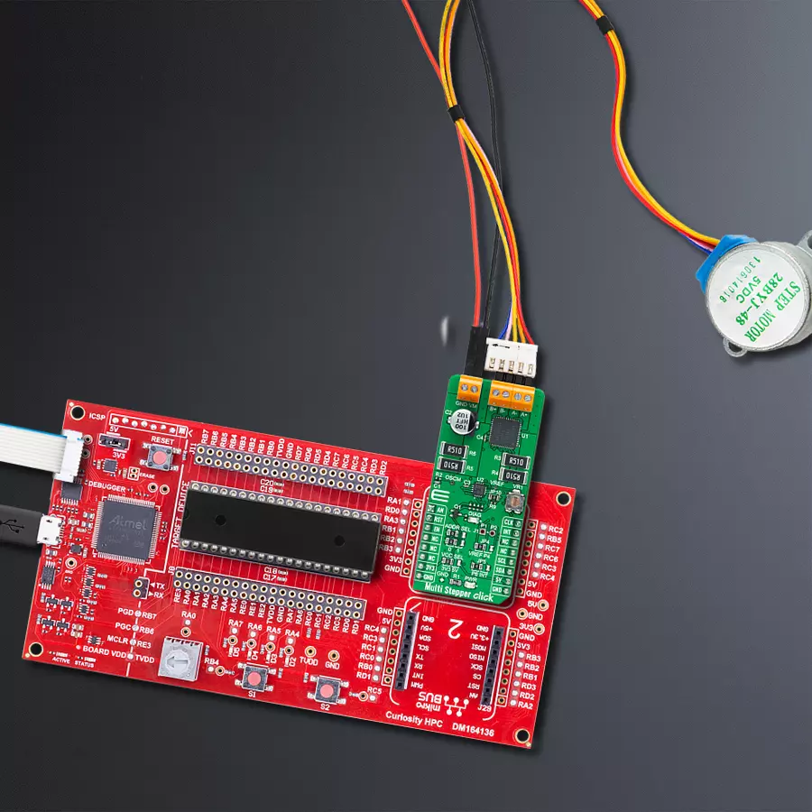
Multi Stepper Click - TB62262
Dev. board
Curiosity HPC
Compiler
NECTO Studio
MCU
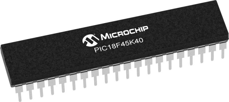
PIC18LF45K40
Unlock the full potential of your motors with our advanced stepper driver - delivering unrivaled control, accuracy, and quiet operation
A
A
Hardware Overview
How does it work?
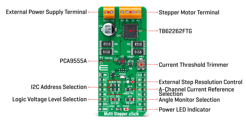
Multi Stepper Click is based on the TB62262FTG, a two-phase bipolar stepping motor driver using a PWM chopper (customized by external resistance R2 and capacitor C1) from Toshiba Semiconductor. The TB62262FTG has a built-in clock-in decoder (CLOCK-in controlled), which means that each up-edge of the CLK signal is routed to the PWM pin of the mikroBUS™ socket, will shift the motor's electrical angle per step. It also incorporates a low on-resistance MOSFET output stage, which can deliver a 1.2A current with a motor output voltage rating of 38V, in addition to integrated protection mechanisms such as over-current and over-temperature detection. In addition, it allows full-, half-, and quarter-step resolution, with the help of which motor noise can be significantly reduced with smoother operation and more precise control. As mentioned, the TB62262FTG supports various step resolution configurations through its control signals. These control signals are provided through the PCA9555A port expander, which establishes communication with the MCU via the I2C serial interface. This Click board™ also allows a connection of external step-resolution control signals on the onboard header J1 on pins labeled as P1 and P2 for the device's DMODE1 and DMODE2 control. The PCA9555A also allows choosing the least significant bit
(LSB) of its I2C slave address by positioning SMD jumpers labeled ADDR SEL to an appropriate position marked as 0 and 1. The output channel's current value can be set manually using an onboard trimmer labeled VR1, which sets the reference voltage from 0V to 3.3V. The default configuration of the JP4 jumper is the VREF position that sets both channels' output current via the VR1 trimmer. In this case, avoid position P4 on a jumper JP4 since the VREFA pin requires an analog signal for setting. Also, this Click board™ has a Standby function, activated when step-resolution control signals are in their low logic state, used to switch to Standby mode by setting all motor control pins to a low logic state. When the Standby mode is active, the TB62262FTG stops supplying the power to the internal oscillating circuit and motor output part (the motor drive cannot be performed). In addition to the I2C communication, several GPIO pins connected to the mikroBUS™ socket are also used. The Enable pin, labeled as EN and routed to the CS pin of the mikroBUS™ socket, optimizes power consumption used for power ON/OFF purposes. Also, a simple rotation direction function routed to the AN pin on the mikroBUS™ socket allows MCU to manage the direction of the stepper motor (clockwise or counterclockwise), while the RST pin of the mikroBUS™
socket initializes an electrical angle in the internal counter to set an initial position. Regarding angle monitoring, this driver has a dual way of monitoring selected by positioning the SMD jumper labeled JP5 to an appropriate position marked as P6 or INT, which chooses to monitor via the expander or INT pin of the mikroBUS™ socket. In the case of the selected INT position of the JP5 jumper, the JP10 jumper needs to be unpopulated. This Click board™ also has an additional LED for anomaly indication, but since this version of the stepper driver does not support this feature, this indicator cannot be used. Multi Stepper Click supports an external power supply for the TB62262FTG, which can be connected to the input terminal labeled as VM and should be within the range of 10V to 38V, while the stepper motor coils can be connected to the terminals labeled as B+, B-, A-, and A+. This Click board™ can operate with either 3.3V or 5V logic voltage levels selected via the VCC SEL jumper. This way, both 3.3V and 5V capable MCUs can use the communication lines properly. However, the Click board™ comes equipped with a library containing easy-to-use functions and an example code that can be used, as a reference, for further development.
Features overview
Development board
Curiosity HPC, standing for Curiosity High Pin Count (HPC) development board, supports 28- and 40-pin 8-bit PIC MCUs specially designed by Microchip for the needs of rapid development of embedded applications. This board has two unique PDIP sockets, surrounded by dual-row expansion headers, allowing connectivity to all pins on the populated PIC MCUs. It also contains a powerful onboard PICkit™ (PKOB), eliminating the need for an external programming/debugging tool, two mikroBUS™ sockets for Click board™ connectivity, a USB connector, a set of indicator LEDs, push button switches and a variable potentiometer. All
these features allow you to combine the strength of Microchip and Mikroe and create custom electronic solutions more efficiently than ever. Each part of the Curiosity HPC development board contains the components necessary for the most efficient operation of the same board. An integrated onboard PICkit™ (PKOB) allows low-voltage programming and in-circuit debugging for all supported devices. When used with the MPLAB® X Integrated Development Environment (IDE, version 3.0 or higher) or MPLAB® Xpress IDE, in-circuit debugging allows users to run, modify, and troubleshoot their custom software and hardware
quickly without the need for additional debugging tools. Besides, it includes a clean and regulated power supply block for the development board via the USB Micro-B connector, alongside all communication methods that mikroBUS™ itself supports. Curiosity HPC development board allows you to create a new application in just a few steps. Natively supported by Microchip software tools, it covers many aspects of prototyping thanks to many number of different Click boards™ (over a thousand boards), the number of which is growing daily.

Microcontroller Overview
MCU Card / MCU
Architecture
PIC
MCU Memory (KB)
32
Silicon Vendor
Microchip
Pin count
40
RAM (Bytes)
2048
You complete me!
Accessories
The 28BYJ-48 is an adaptable 5VDC stepper motor with a compact design, ideal for various applications. It features four phases, a speed variation ratio of 1/64, and a stride angle of 5.625°/64 steps, allowing precise control. The motor operates at a frequency of 100Hz and has a DC resistance of 50Ω ±7% at 25°C. It boasts an idle in-traction frequency greater than 600Hz and an idle out-traction frequency exceeding 1000Hz, ensuring reliability in different scenarios. With a self-positioning torque and in-traction torque both exceeding 34.3mN.m at 120Hz, the 28BYJ-48 offers robust performance. Its friction torque ranges from 600 to 1200 gf.cm, while the pull-in torque is 300 gf.cm. This motor makes a reliable and efficient choice for your stepper motor needs.

Used MCU Pins
mikroBUS™ mapper
Take a closer look
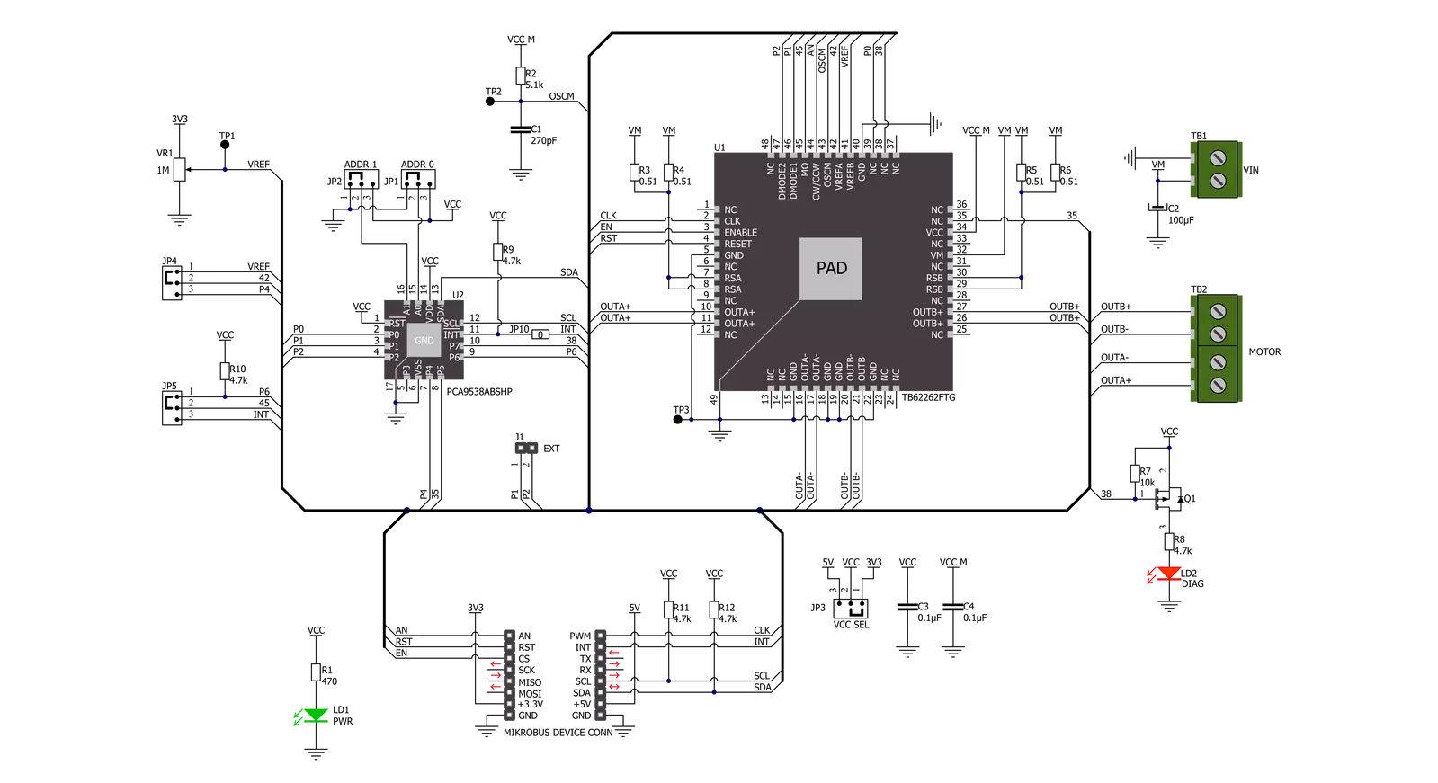
Click board™ Schematic
Step by step
Project assembly

Start by selecting your development board and Click board™. Begin with the Curiosity HPC as your development board.


Track your results in real time
Application Output
1. Application Output - In Debug mode, the 'Application Output' window enables real-time data monitoring, offering direct insight into execution results. Ensure proper data display by configuring the environment correctly using the provided tutorial.

2. UART Terminal - Use the UART Terminal to monitor data transmission via a USB to UART converter, allowing direct communication between the Click board™ and your development system. Configure the baud rate and other serial settings according to your project's requirements to ensure proper functionality. For step-by-step setup instructions, refer to the provided tutorial.

3. Plot Output - The Plot feature offers a powerful way to visualize real-time sensor data, enabling trend analysis, debugging, and comparison of multiple data points. To set it up correctly, follow the provided tutorial, which includes a step-by-step example of using the Plot feature to display Click board™ readings. To use the Plot feature in your code, use the function: plot(*insert_graph_name*, variable_name);. This is a general format, and it is up to the user to replace 'insert_graph_name' with the actual graph name and 'variable_name' with the parameter to be displayed.

Software Support
Library Description
This library contains API for Multi Stepper TB62262 Click driver.
Key functions:
multisteppertb62262_set_step_modeThis function sets the step mode resolution settings.multisteppertb62262_drive_motorThis function drives the motor for the specific number of steps at the selected speed.multisteppertb62262_set_directionThis function sets the motor direction by setting the AN pin logic state.
Open Source
Code example
The complete application code and a ready-to-use project are available through the NECTO Studio Package Manager for direct installation in the NECTO Studio. The application code can also be found on the MIKROE GitHub account.
/*!
 * @file main.c
 * @brief MultiStepperTB62262 Click example
 *
 * # Description
 * This example demonstrates the use of the Multi Stepper TB62262 Click board by driving the
 * motor in both directions for a desired number of steps.
 *
 * The demo application is composed of two sections :
 *
 * ## Application Init
 * Initializes the driver and performs the Click default configuration.
 *
 * ## Application Task
 * Drives the motor clockwise for 200 steps and then counter-clockiwse for 100 steps with
 * 2 seconds delay before changing the direction.
 * Each step will be logged on the USB UART where you can track the program flow.
 *
 * @author Stefan Filipovic
 *
 */

#include "board.h"
#include "log.h"
#include "multisteppertb62262.h"

static multisteppertb62262_t multisteppertb62262;
static log_t logger;

void application_init ( void )
{
    log_cfg_t log_cfg;  /**< Logger config object. */
    multisteppertb62262_cfg_t multisteppertb62262_cfg;  /**< Click config object. */

    /**
     * Logger initialization.
     * Default baud rate: 115200
     * Default log level: LOG_LEVEL_DEBUG
     * @note If USB_UART_RX and USB_UART_TX
     * are defined as HAL_PIN_NC, you will
     * need to define them manually for log to work.
     * See @b LOG_MAP_USB_UART macro definition for detailed explanation.
     */
    LOG_MAP_USB_UART( log_cfg );
    log_init( &logger, &log_cfg );
    log_info( &logger, " Application Init " );

    // Click initialization.
    multisteppertb62262_cfg_setup( &multisteppertb62262_cfg );
    MULTISTEPPERTB62262_MAP_MIKROBUS( multisteppertb62262_cfg, MIKROBUS_1 );
    if ( I2C_MASTER_ERROR == multisteppertb62262_init( &multisteppertb62262, &multisteppertb62262_cfg ) )
    {
        log_error( &logger, " Communication init." );
        for ( ; ; );
    }

    if ( MULTISTEPPERTB62262_ERROR == multisteppertb62262_default_cfg ( &multisteppertb62262 ) )
    {
        log_error( &logger, " Default configuration." );
        for ( ; ; );
    }

    log_info( &logger, " Application Task " );
}

void application_task ( void )
{
    log_printf ( &logger, " Move 200 steps clockwise \r\n\n" );
    multisteppertb62262_set_direction ( &multisteppertb62262, MULTISTEPPERTB62262_DIR_CW );
    multisteppertb62262_drive_motor ( &multisteppertb62262, 200, MULTISTEPPERTB62262_SPEED_FAST );
    Delay_ms ( 1000 );
    Delay_ms ( 1000 );

    log_printf ( &logger, " Move 100 steps counter-clockwise \r\n\n" );
    multisteppertb62262_set_direction ( &multisteppertb62262, MULTISTEPPERTB62262_DIR_CCW );
    multisteppertb62262_drive_motor ( &multisteppertb62262, 100, MULTISTEPPERTB62262_SPEED_FAST );
    Delay_ms ( 1000 );
    Delay_ms ( 1000 );
}

int main ( void )
{
    /* Do not remove this line or clock might not be set correctly. */
    #ifdef PREINIT_SUPPORTED
    preinit();
    #endif

    application_init( );

    for ( ; ; )
    {
        application_task( );
    }

    return 0;
}

// ------------------------------------------------------------------------ END
Additional Support
Resources
Category:Stepper


