Provide highly accurate real-time clock and calendar functions with the DS1307 and STM32L496AG
Battery-backed real-time clock solution for continuous tracking
Published Jul 22, 2025
Click board™
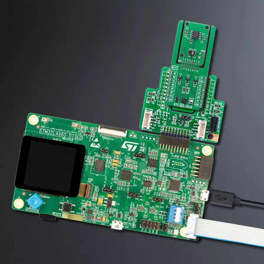
RTC 24 Click
Dev. board
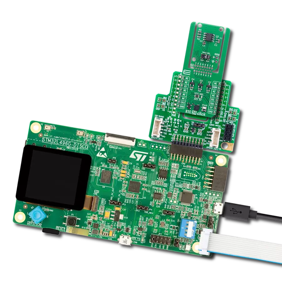
Discovery kit with STM32L496AG MCU
Compiler
NECTO Studio
MCU
STM32L496AG
Ensure your data loggers and metering systems maintain accurate timestamps with robust real-time clock capabilities
A
A
Hardware Overview
How does it work?
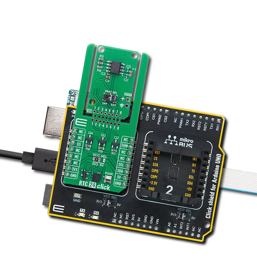
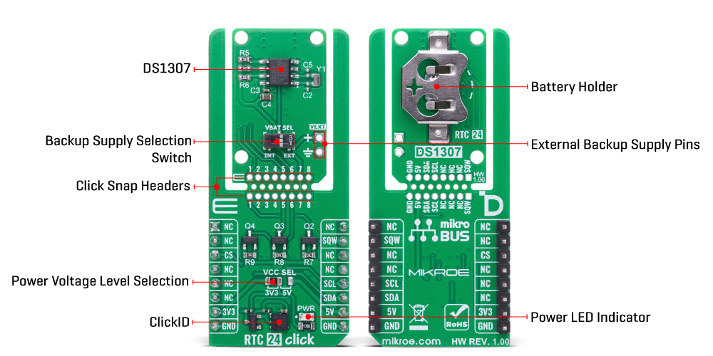
RTC 24 Click is based on the DS1307, a serial real-time clock (RTC) module from Analog Devices, which features a 64x8 bit battery-backed NV SRAM alongside its full binary-coded decimal (BCD) clock/calendar functionality. This board provides highly accurate real-time clock and calendar functions for embedded applications, enabling precise timekeeping even during power interruptions. The clock/calendar maintains complete time data, including seconds, minutes, hours, day, date, month, and year, with built-in logic to automatically adjust the date at the end of each month, accounting for months with fewer than 31 days and incorporating leap-year compensation valid up to the year 2100. The device supports both 24-hour and 12-hour formats with an AM/PM indicator, making it flexible for various regional and application-specific requirements. This Click board™ is designed in a unique format supporting the newly introduced MIKROE feature called "Click Snap." Unlike the standardized version of Click
boards, this feature allows the main sensor area to become movable by breaking the PCB, opening up many new possibilities for implementation. Thanks to the Snap feature, the DS1307 can operate autonomously by accessing its signals directly on the pins marked 1-8. Additionally, the Snap part includes a specified and fixed screw hole position, enabling users to secure the Snap board in their desired location. Communication with the host MCU is established through a standard I2C interface, allowing for straightforward integration and reliable data transfer. In addition to the standard I2C pins, RTC 24 Click uses the SQW pin, which can output one of four selectable square-wave frequencies: 1Hz, 4kHz, 8kHz, or 32kHz, allowing the board to provide an accurate clock signal or act as an output driver for synchronization purposes in complex systems. The board also integrates a VBAT SEL switch that allows users to select the backup power source for the RTC module. This switch enables the selection between the onboard lithium cell battery
or an external 3V backup supply provided via the VEXT pin, located directly next to the switch, ensuring uninterrupted operation and flexible power management depending on system design requirements. A built-in power-sense circuit within the DS1307 automatically detects power failures and switches to the selected backup supply, preserving timekeeping data at all times. This combination of features makes RTC 24 Click an ideal solution for applications such as data loggers, metering systems, industrial automation, and any embedded system that requires dependable and continuous real-time tracking. This Click board™ can operate with either 3.3V or 5V logic voltage levels selected via the VCC SEL jumper. This way, both 3.3V and 5V capable MCUs can use the communication lines properly. Also, this Click board™ comes equipped with a library containing easy-to-use functions and an example code that can be used as a reference for further development.
Features overview
Development board
The 32L496GDISCOVERY Discovery kit serves as a comprehensive demonstration and development platform for the STM32L496AG microcontroller, featuring an Arm® Cortex®-M4 core. Designed for applications that demand a balance of high performance, advanced graphics, and ultra-low power consumption, this kit enables seamless prototyping for a wide range of embedded solutions. With its innovative energy-efficient
architecture, the STM32L496AG integrates extended RAM and the Chrom-ART Accelerator, enhancing graphics performance while maintaining low power consumption. This makes the kit particularly well-suited for applications involving audio processing, graphical user interfaces, and real-time data acquisition, where energy efficiency is a key requirement. For ease of development, the board includes an onboard ST-LINK/V2-1
debugger/programmer, providing a seamless out-of-the-box experience for loading, debugging, and testing applications without requiring additional hardware. The combination of low power features, enhanced memory capabilities, and built-in debugging tools makes the 32L496GDISCOVERY kit an ideal choice for prototyping advanced embedded systems with state-of-the-art energy efficiency.

Microcontroller Overview
MCU Card / MCU

Architecture
ARM Cortex-M4
MCU Memory (KB)
1024
Silicon Vendor
STMicroelectronics
Pin count
169
RAM (Bytes)
327680
Used MCU Pins
mikroBUS™ mapper
Take a closer look
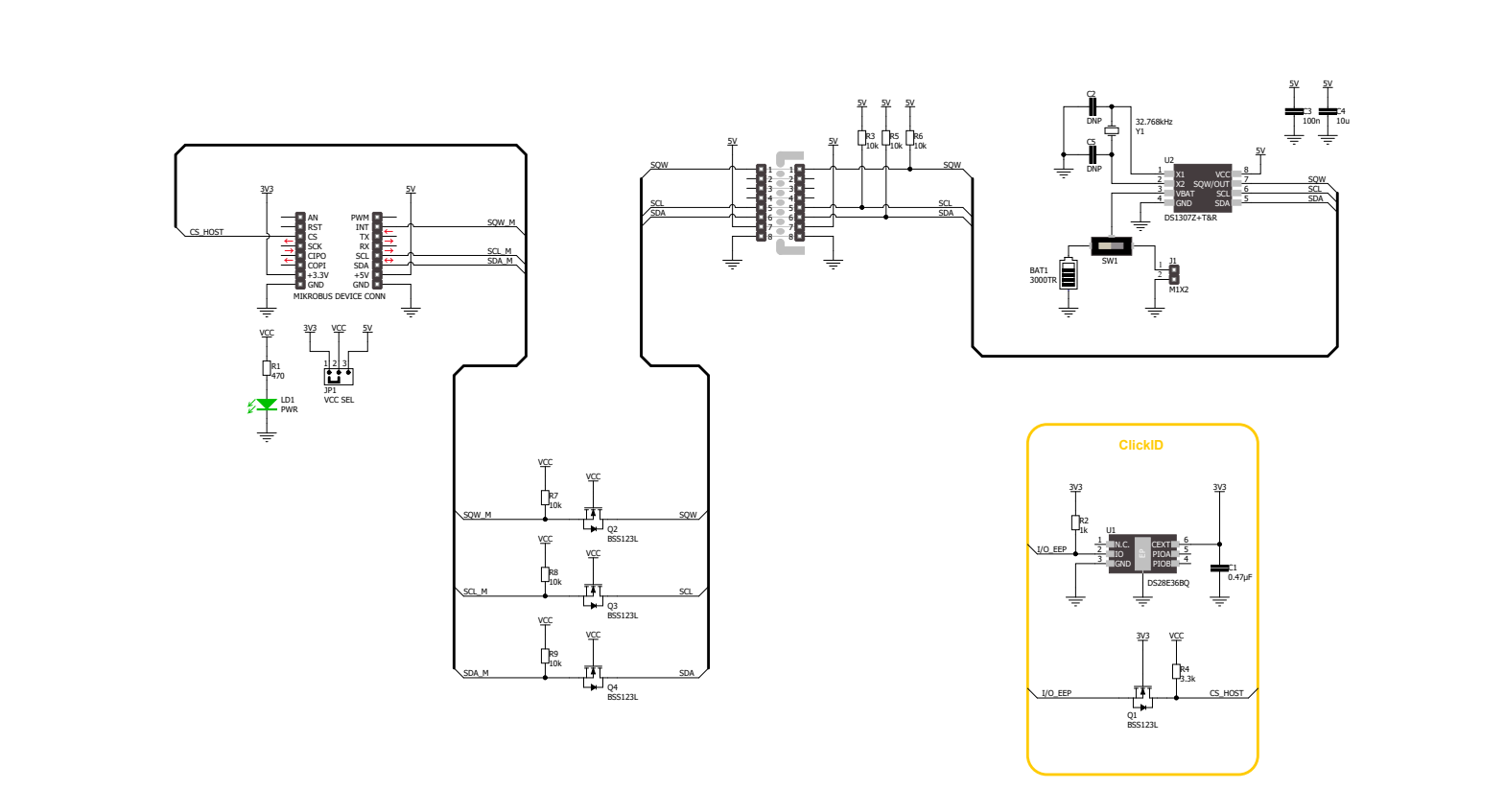
Click board™ Schematic
Step by step
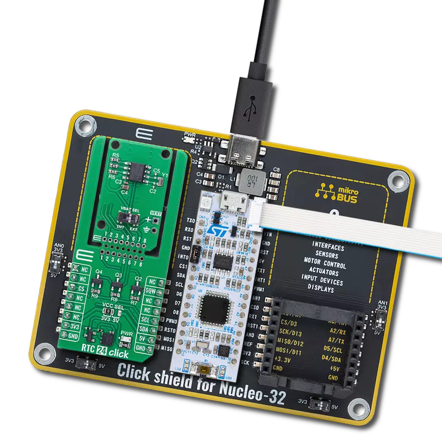
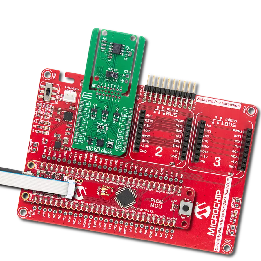
Project assembly

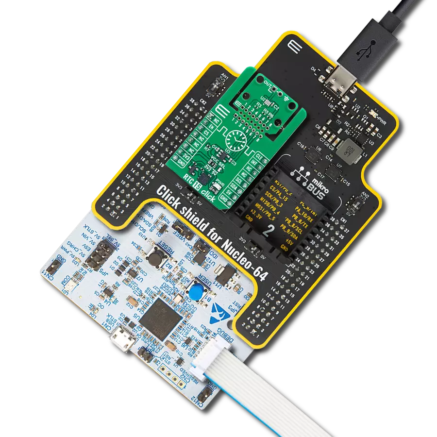
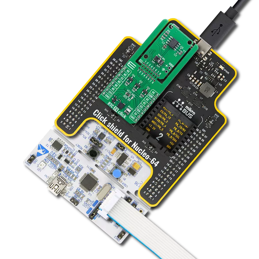
Start by selecting your development board and Click board™. Begin with the Discovery kit with STM32L496AG MCU as your development board.


Software Support
Library Description
RTC 24 Click demo application is developed using the NECTO Studio, ensuring compatibility with mikroSDK's open-source libraries and tools. Designed for plug-and-play implementation and testing, the demo is fully compatible with all development, starter, and mikromedia boards featuring a mikroBUS™ socket.
Example Description
This example demonstrates the use of the RTC 24 Click board by initializing the device and setting up the current time and date. It continuously reads and displays the updated time and date every second using the square wave pin.
Key functions:
rtc24_cfg_setup- This function initializes Click configuration structure to initial values.rtc24_init- This function initializes all necessary pins and peripherals used for this Click board.rtc24_default_cfg- This function executes a default configuration of RTC 24 Click board.rtc24_set_time- This function sets the current time (hours, minutes, seconds) in the RTC.rtc24_read_time- This function reads the current time (hours, minutes, seconds) from the RTC.rtc24_read_date- This function reads the current date (day, day of week, month, year) from the RTC.
Application Init
Initializes the logger and the RTC 24 Click driver, applies the default configuration, and sets the starting time and date.
Application Task
Waits for a 1 Hz square wave signal and then reads and displays the current time and date.
Open Source
Code example
The complete application code and a ready-to-use project are available through the NECTO Studio Package Manager for direct installation in the NECTO Studio. The application code can also be found on the MIKROE GitHub account.
/*!
 * @file main.c
 * @brief RTC 24 Click example
 *
 * # Description
 * This example demonstrates the use of the RTC 24 Click board by initializing
 * the device and setting up the current time and date. It continuously
 * reads and displays the updated time and date every second using the square wave pin.
 *
 * The demo application is composed of two sections:
 *
 * ## Application Init
 * Initializes the logger and the RTC 24 Click driver, applies the default configuration,
 * and sets the starting time and date.
 *
 * ## Application Task
 * Waits for a 1 Hz square wave signal and then reads and displays the current time and date.
 *
 * @author Stefan Filipovic
 *
 */

#include "board.h"
#include "log.h"
#include "rtc24.h"

static rtc24_t rtc24;
static log_t logger;
static rtc24_time_t time;
static rtc24_date_t date;

/**
 * @brief RTC 24 get day of week name function.
 * @details This function returns the name of day of the week as a string.
 * @param[in] ctx : Click context object.
 * See #rtc24_t object definition for detailed explanation.
 * @param[in] day_of_week : Day of week decimal value.
 * @return Name of day as a string.
 * @note None.
 */
static uint8_t *rtc24_get_day_of_week_name ( uint8_t day_of_week );

void application_init ( void )
{
    log_cfg_t log_cfg;  /**< Logger config object. */
    rtc24_cfg_t rtc24_cfg;  /**< Click config object. */

    /**
     * Logger initialization.
     * Default baud rate: 124200
     * Default log level: LOG_LEVEL_DEBUG
     * @note If USB_UART_RX and USB_UART_TX
     * are defined as HAL_PIN_NC, you will
     * need to define them manually for log to work.
     * See @b LOG_MAP_USB_UART macro definition for detailed explanation.
     */
    LOG_MAP_USB_UART( log_cfg );
    log_init( &logger, &log_cfg );
    log_info( &logger, " Application Init " );

    // Click initialization.
    rtc24_cfg_setup( &rtc24_cfg );
    RTC24_MAP_MIKROBUS( rtc24_cfg, MIKROBUS_1 );
    if ( I2C_MASTER_ERROR == rtc24_init( &rtc24, &rtc24_cfg ) )
    {
        log_error( &logger, " Communication init." );
        for ( ; ; );
    }

    if ( RTC24_ERROR == rtc24_default_cfg ( &rtc24 ) )
    {
        log_error( &logger, " Default configuration." );
        for ( ; ; );
    }

    time.hour = 23;
    time.minute = 59;
    time.second = 50;
    if ( RTC24_OK == rtc24_set_time ( &rtc24, &time ) )
    {
        log_printf( &logger, " Set time: %.2u:%.2u:%.2u\r\n",
                    ( uint16_t ) time.hour, ( uint16_t ) time.minute, ( uint16_t ) time.second );
    }
    date.day_of_week = RTC24_TUESDAY;
    date.day = 31;
    date.month = 12;
    date.year = 24;
    if ( RTC24_OK == rtc24_set_date ( &rtc24, &date ) )
    {
        log_printf( &logger, " Set date: %s, %.2u.%.2u.20%.2u.\r\n",
                    rtc24_get_day_of_week_name ( date.day_of_week ),
                    ( uint16_t ) date.day, ( uint16_t ) date.month, ( uint16_t ) date.year );
    }

    log_info( &logger, " Application Task " );
}

void application_task ( void )
{
    // Wait for a square wave output configured at 1 Hz
    while ( rtc24_get_sqw_pin ( &rtc24 ) );
    while ( !rtc24_get_sqw_pin ( &rtc24 ) );

    if ( RTC24_OK == rtc24_read_time ( &rtc24, &time ) )
    {
        log_printf( &logger, " Time: %.2u:%.2u:%.2u\r\n",
                    ( uint16_t ) time.hour, ( uint16_t ) time.minute, ( uint16_t ) time.second );
    }
    if ( RTC24_OK == rtc24_read_date ( &rtc24, &date ) )
    {
        log_printf( &logger, " Date: %s, %.2u.%.2u.20%.2u.\r\n\n",
                    rtc24_get_day_of_week_name ( date.day_of_week ),
                    ( uint16_t ) date.day, ( uint16_t ) date.month, ( uint16_t ) date.year );
    }
}

int main ( void )
{
    /* Do not remove this line or clock might not be set correctly. */
    #ifdef PREINIT_SUPPORTED
    preinit();
    #endif

    application_init( );

    for ( ; ; )
    {
        application_task( );
    }

    return 0;
}

static uint8_t *rtc24_get_day_of_week_name ( uint8_t day_of_week )
{
    switch ( day_of_week )
    {
        case RTC24_MONDAY:
        {
            return "Monday";
        }
        case RTC24_TUESDAY:
        {
            return "Tuesday";
        }
        case RTC24_WEDNESDAY:
        {
            return "Wednesday";
        }
        case RTC24_THURSDAY:
        {
            return "Thursday";
        }
        case RTC24_FRIDAY:
        {
            return "Friday";
        }
        case RTC24_SATURDAY:
        {
            return "Saturday";
        }
        case RTC24_SUNDAY:
        {
            return "Sunday";
        }
        default:
        {
            return "Unknown";
        }
    }
}

// ------------------------------------------------------------------------ END
Additional Support
Resources
Category:RTC