Experience high-quality wireless audio streaming over Bluetooth 5.4 with the IDC777-1 and PIC32MZ1024EFH064
High-quality Bluetooth 5.4 (LE Audio) solution for advanced wireless audio streaming and communication
Published Aug 11, 2025
Click board™
BT Audio 4 Click
Dev. board
PIC32MZ clicker
Compiler
NECTO Studio
MCU
PIC32MZ1024EFH064
High-quality wireless audio streaming and Bluetooth communication with full headset functionality in both Classic and LE Audio modes
A
A
Hardware Overview
How does it work?
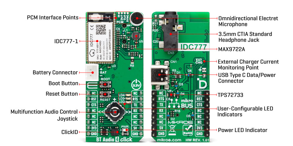
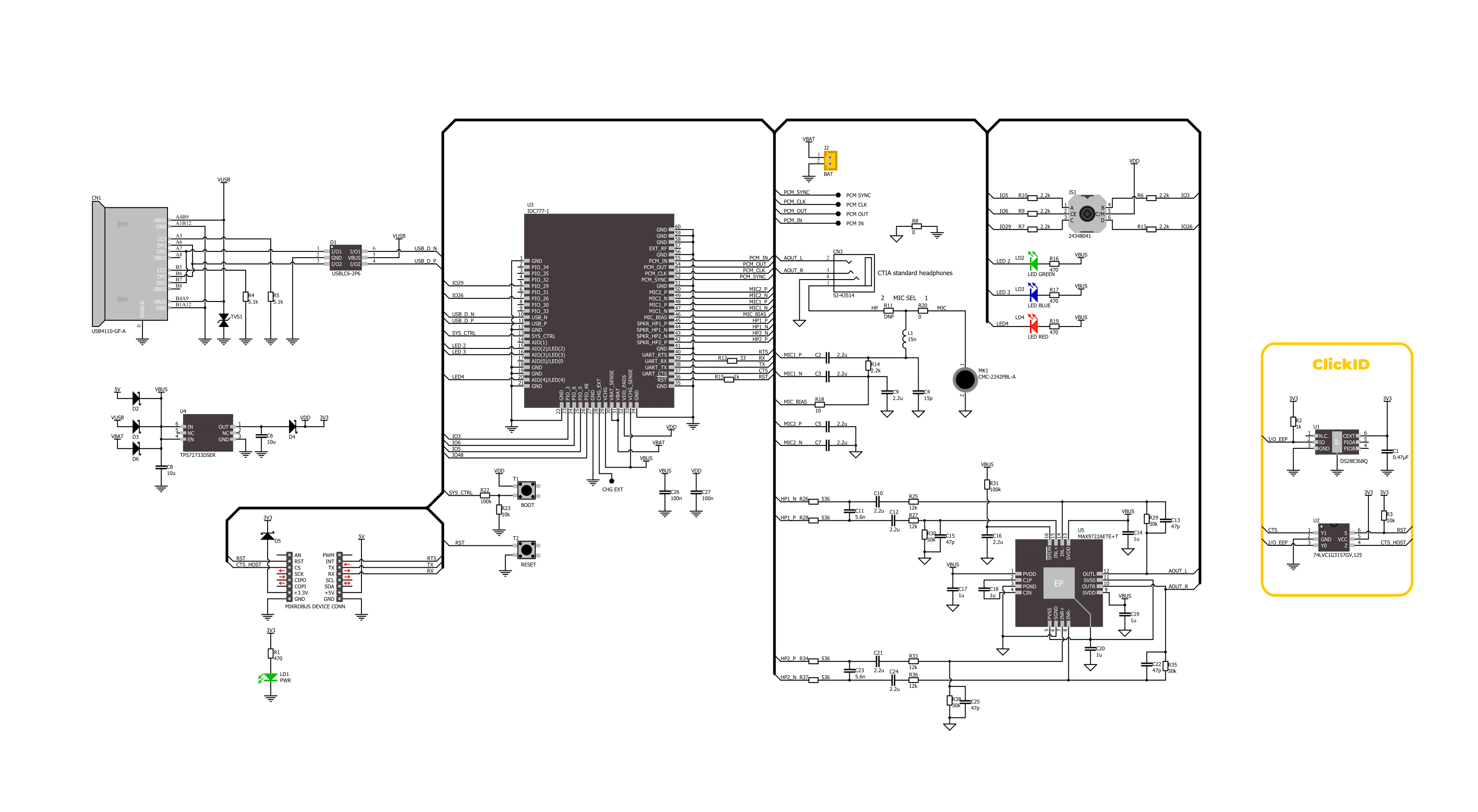
BT Audio 4 Click is based on the IDC777-1 module from IOT747 that enables high-quality wireless audio and data communication over Bluetooth. This fully integrated solution supports both Bluetooth Classic and LE Audio modes, including the latest LE Audio Unicast and Auracast (Broadcast) functionalities using the advanced LC3 codec. The IDC777-1 is controlled via a simple UART interface that also handles data transmission, and supports multiple simultaneous connections and profiles such as HFP, A2DP (Sink and Source), AVRCP, SPP, and BLE, making it ideal for both receiver and transmitter roles in complex audio systems, including audio-visual products, industrial audio and data interfaces, automotive and aerospace applications, teleconferencing equipment, and various retail, sports, and leisure devices. The module offers extremely low power consumption, making it ideal for battery-powered applications. With a typical RF sensitivity of -97dBm and a maximum transmit power of 9dBm, the IDC777-1 ensures stable connectivity within a 25-meter range. Audio interfaces include both analog and digital options such as I2S, PCM, and SPDIF, and the module supports advanced audio standards including aptX, aptX HD, aptX Lossless, AAC, and Wide Band Speech. Certified for global use with approvals including FCC (US), RED (Europe), MIC (Japan), KCC (Korea), and SRRC (China), the module is also supplied with reference Android and iOS apps to accelerate development. The IDC777-1 operates exclusively at 3.3V, while the board
accepts power from multiple sources, including the 5V mikroBUS™ rail, USB connector, or an external battery via the BAT connector. A low-dropout regulator, the TPS72733, converts these inputs to a clean and stable 3.3V supply required for the module’s optimal operation. The BT Audio 4 Click supports both digital and analog audio paths, enabling versatile Bluetooth audio applications. The IDC777-1 provides a PCM interface for connecting to external digital audio devices, with signals routed to clearly labeled test points on the board. It supports sample rates up to 384kHz for DAC and up to 96kHz for ADC, allowing integration with high-quality audio systems. In addition to digital audio, the board also features the MAX9722A stereo headphone amplifier paired with a CTIA-compliant 3.5mm jack for driving standard headphones with microphone support, and a CMC-2242PBL-A omnidirectional electret microphone for voice input, enabling hands-free calls, voice control, or audio streaming. Combined with the IDC777-1’s processing, the board functions as a complete Bluetooth headset or audio interface for both playback and voice transmission. Communication between the IDC777-1 and the host MCU is made through a UART interface, using standard UART RX and TX pins and hardware flow control pins (CTS/RTS- Clear to Send/Ready to Send) for efficient data transfer. The module defaults to a communication speed of 115200bps, allowing data exchange over AT commands. Along with the communication and control pins, this Click board™
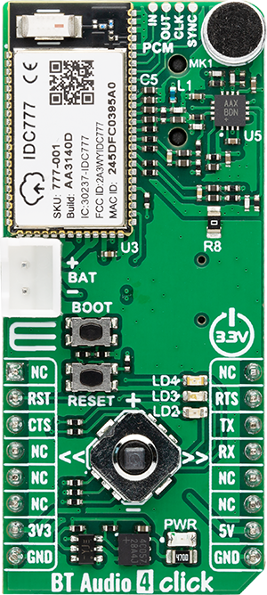
also includes a reset pin (RST) and a RESET button, enabling easy module resetting, and a BOOT button. The BOOT button can be used to initiate the module’s boot sequence or to wake it from a dormant or sleep state, providing convenient control during development, pairing, or low-power operation scenarios. BT Audio 4 Click features three user-configurable LEDs in red, blue, and green, which can be used to indicate device status, connection state, streaming activity, or other custom functions, depending on application requirements. It also includes a multifunctional 5-directional joystick that provides intuitive audio control, allowing the user to adjust volume (up/down), navigate tracks (left/right), and control playback with a press for play/pause functionality. On the back side of the board, a dedicated test point labeled EXT CHG is available, reserved for external charger current monitoring. Although not used in this design, it is provided for optional measurement or debugging, as recommended in the IDC777-1 datasheet. While both mikroBUS™ power rails are available, BT Audio 4 Click operates exclusively on a 3.3V logic level, which is required by the IDC777-1 module. Therefore, level shifting must be performed when interfacing with MCUs that use different logic voltages. The board also comes equipped with a library containing functions and example code that can be used as a reference for further development.
Features overview
Development board
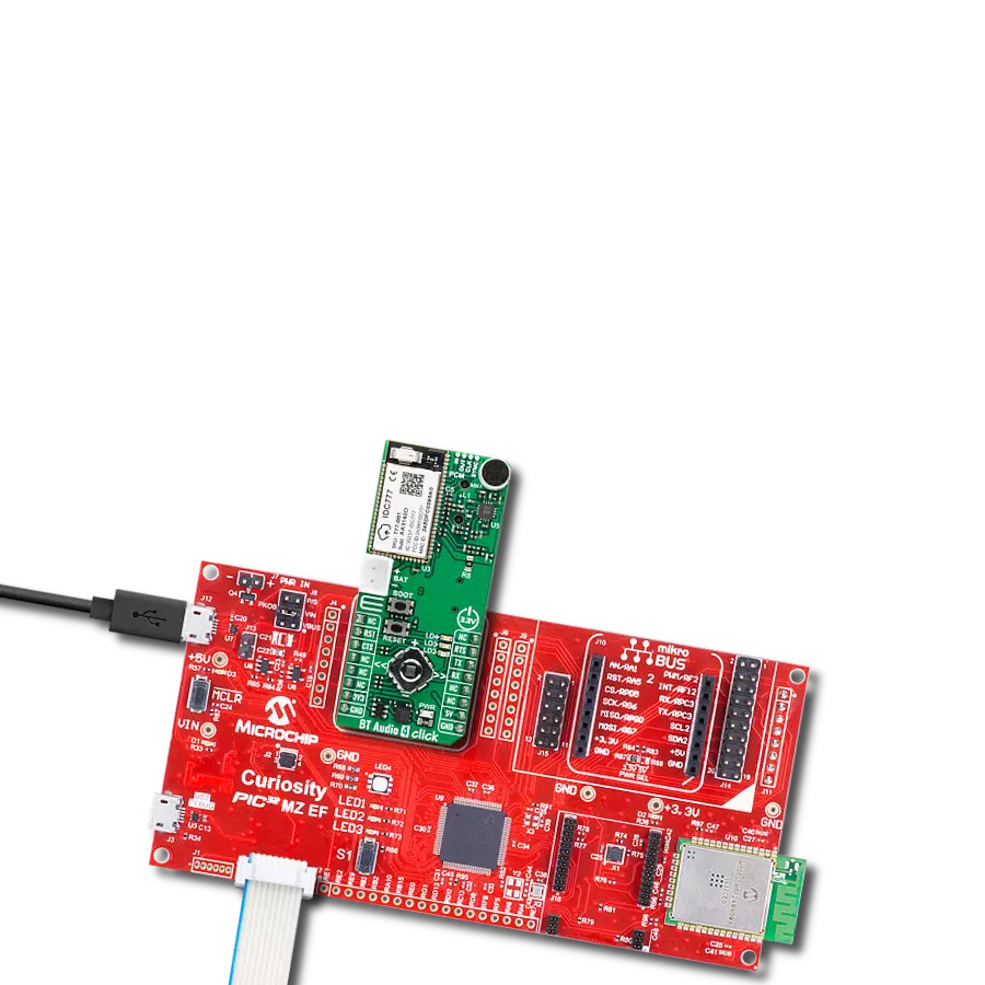
PIC32MZ Clicker is a compact starter development board that brings the flexibility of add-on Click boards™ to your favorite microcontroller, making it a perfect starter kit for implementing your ideas. It comes with an onboard 32-bit PIC32MZ microcontroller with FPU from Microchip, a USB connector, LED indicators, buttons, a mikroProg connector, and a header for interfacing with external electronics. Thanks to its compact design with clear and easy-recognizable silkscreen markings, it provides a fluid and immersive working experience, allowing access anywhere and under
any circumstances. Each part of the PIC32MZ Clicker development kit contains the components necessary for the most efficient operation of the same board. In addition to the possibility of choosing the PIC32MZ Clicker programming method, using USB HID mikroBootloader, or through an external mikroProg connector for PIC, dsPIC, or PIC32 programmer, the Clicker board also includes a clean and regulated power supply module for the development kit. The USB Micro-B connection can provide up to 500mA of current, which is more than enough to operate all onboard
and additional modules. All communication methods that mikroBUS™ itself supports are on this board, including the well-established mikroBUS™ socket, reset button, and several buttons and LED indicators. PIC32MZ Clicker is an integral part of the Mikroe ecosystem, allowing you to create a new application in minutes. Natively supported by Mikroe software tools, it covers many aspects of prototyping thanks to a considerable number of different Click boards™ (over a thousand boards), the number of which is growing every day.

Microcontroller Overview
MCU Card / MCU

Architecture
PIC32
MCU Memory (KB)
1024
Silicon Vendor
Microchip
Pin count
64
RAM (Bytes)
524288
You complete me!
Accessories
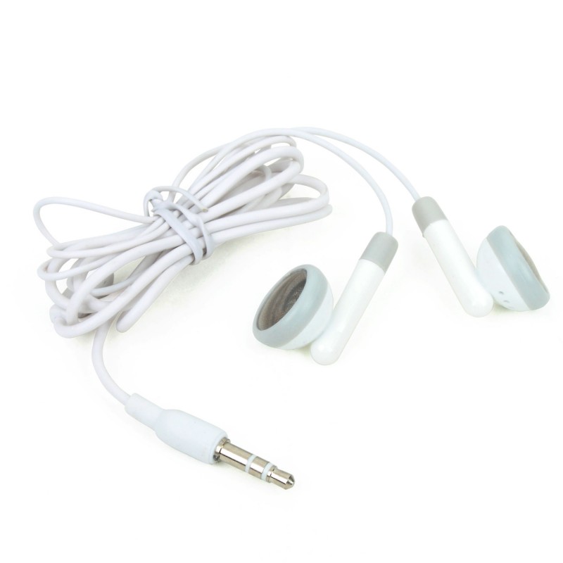
These standard small stereo earphones offer a high-quality listening experience with their top-notch stereo cable and connector. Designed for universal compatibility, they effortlessly connect to all MIKROE mikromedia and multimedia boards, making them an ideal choice for your electronic projects. With a rated power of 100mW, the earphones provide crisp audio across a broad frequency range from 20Hz to 20kHz. They boast a sensitivity of 100 ± 5dB and an impedance of 32Ω ± 15%, ensuring optimal sound quality. The Φ15mm speaker delivers clear and immersive audio. Cost-effective and versatile, these earphones are perfect for testing your prototype devices, offering an affordable and reliable audio solution to complement your projects.
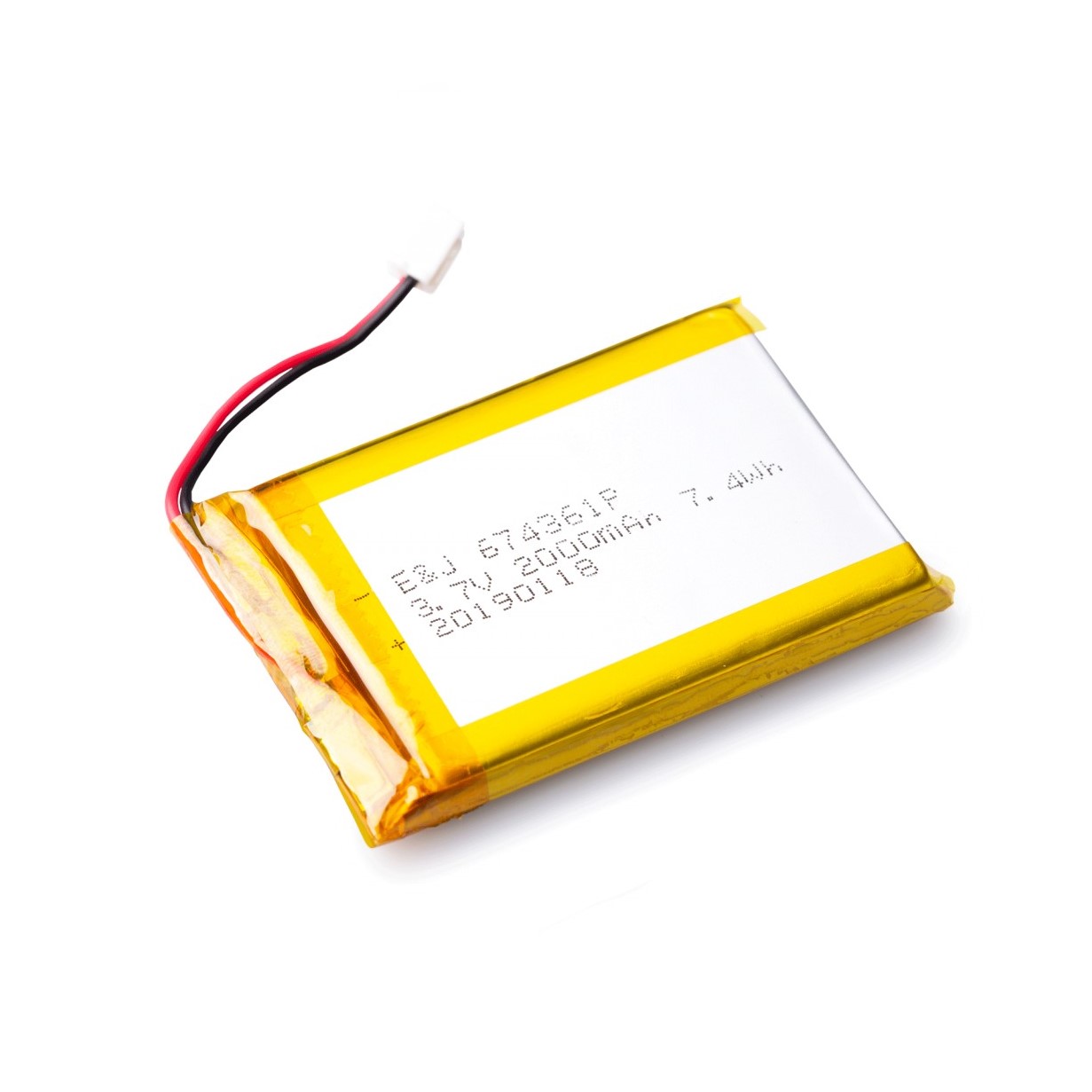
Li-Polymer Battery is the ideal solution for devices that demand a dependable and long-lasting power supply while emphasizing mobility. Its compatibility with mikromedia boards ensures easy integration without additional modifications. With a voltage output of 3.7V, the battery meets the standard requirements of many electronic devices. Additionally, boasting a capacity of 2000mAh, it can store a substantial amount of energy, providing sustained power for extended periods. This feature minimizes the need for frequent recharging or replacement. Overall, the Li-Polymer Battery is a reliable and autonomous power source, ideally suited for devices requiring a stable and enduring energy solution.
Used MCU Pins
mikroBUS™ mapper
Take a closer look
Click board™ Schematic
Step by step
Project assembly

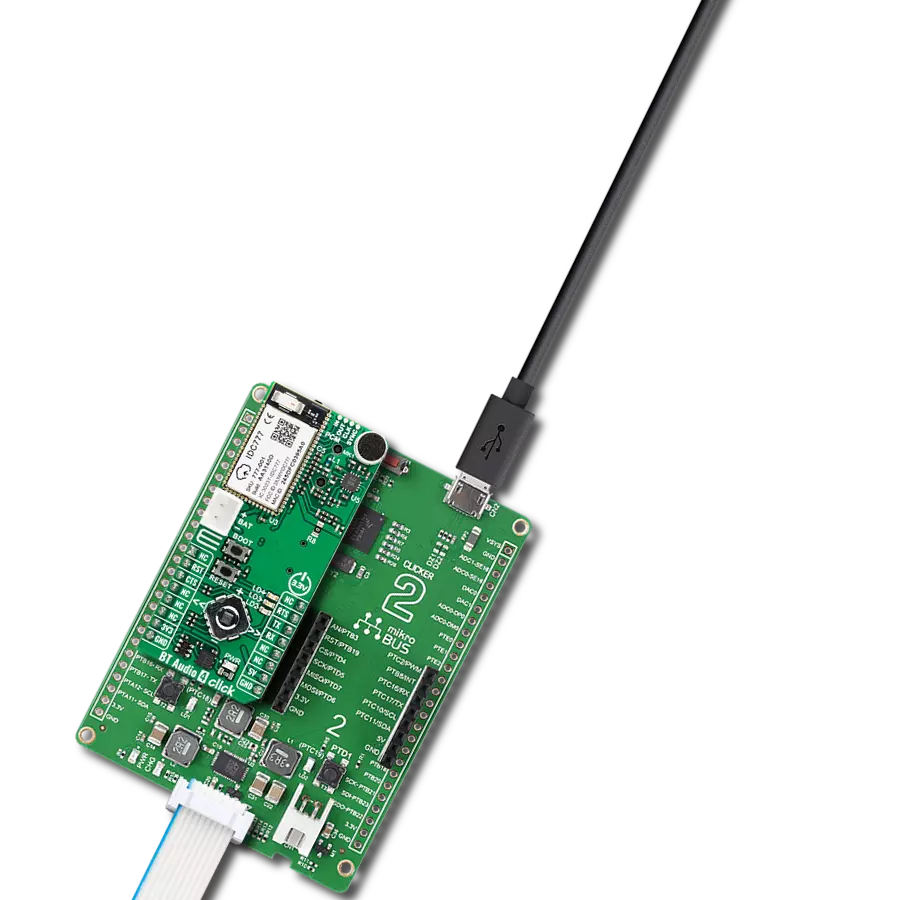
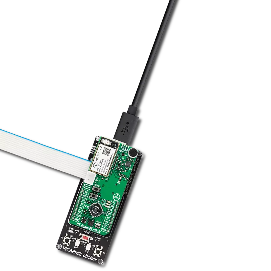
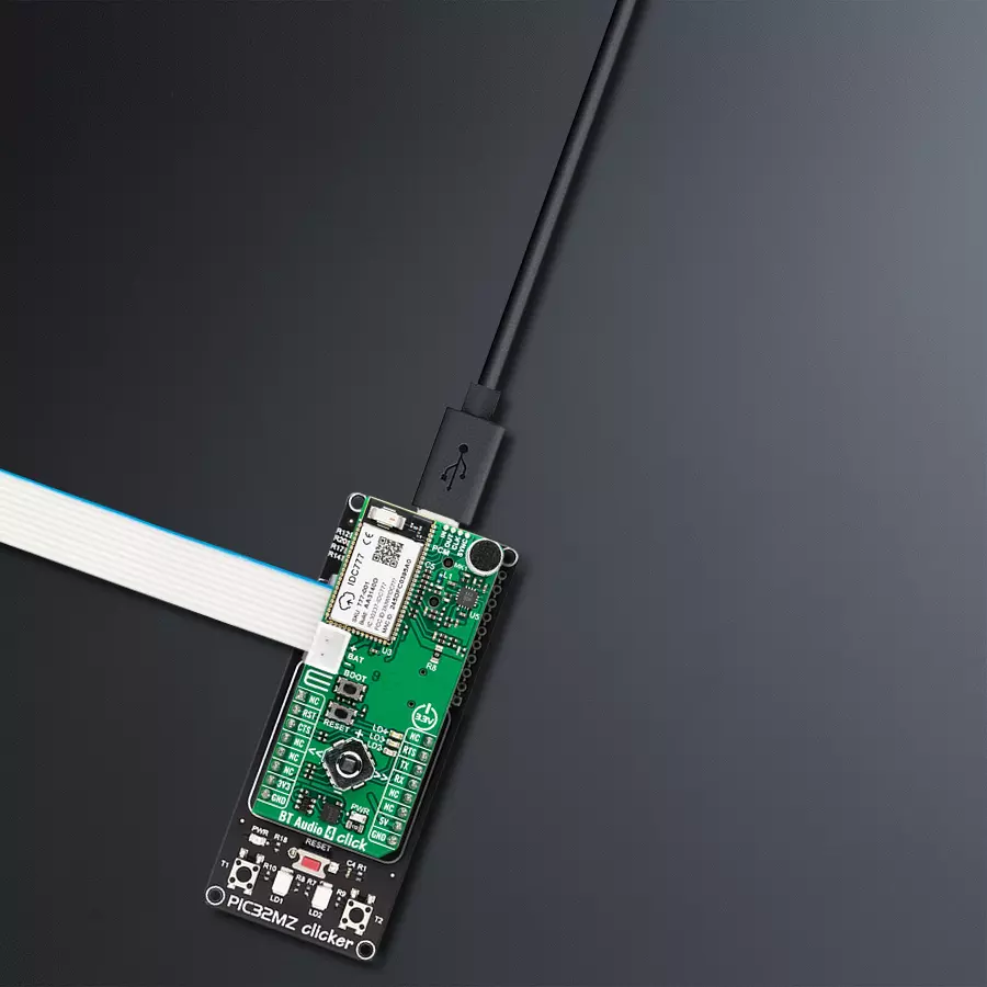
Start by selecting your development board and Click board™. Begin with the PIC32MZ clicker as your development board.


Software Support
Library Description
BT Audio 4 Click demo application is developed using the NECTO Studio, ensuring compatibility with mikroSDK's open-source libraries and tools. Designed for plug-and-play implementation and testing, the demo is fully compatible with all development, starter, and mikromedia boards featuring a mikroBUS™ socket.
Example Description
This example demonstrates how to communicate with the BT Audio 4 Click board over UART. It initializes the device, resets it, retrieves the device name, and then continuously processes and logs any incoming UART messages from the device.
Key functions:
btaudio4_cfg_setup- This function initializes Click configuration structure to initial values.btaudio4_init- This function initializes all necessary pins and peripherals used for this Click board.btaudio4_cmd_run- This function sends a specified command to the Click module.btaudio4_cmd_set- This function sets a value to a specified command parameter of the Click module.btaudio4_cmd_get- This function is used to get the value of a given command parameter from the Click module.
Application Init
Initializes the logger and the BT Audio 4 Click driver, performs a device reset, and reads the device name.
Application Task
Continuously processes UART data received from the Click board and logs it to the terminal. Acts as a passive receiver of incoming messages, useful for monitoring notifications.
Open Source
Code example
The complete application code and a ready-to-use project are available through the NECTO Studio Package Manager for direct installation in the NECTO Studio. The application code can also be found on the MIKROE GitHub account.
/*!
 * @file main.c
 * @brief BT Audio 4 Click Example.
 *
 * # Description
 * This example demonstrates how to communicate with the BT Audio 4 Click board over UART.
 * It initializes the device, resets it, retrieves the device name, and then continuously
 * processes and logs any incoming UART messages from the device.
 *
 * The demo application is composed of two sections :
 *
 * ## Application Init
 * Initializes the logger and the BT Audio 4 Click driver, performs a device reset,
 * and reads the device name.
 *
 * ## Application Task
 * Continuously processes UART data received from the Click board and logs it to the terminal.
 * Acts as a passive receiver of incoming messages, useful for monitoring notifications.
 *
 * ## Additional Function
 * - static void btaudio4_clear_app_buf ( void )
 * - static void btaudio4_log_app_buf ( void )
 * - static err_t btaudio4_process ( btaudio4_t *ctx )
 * - static err_t btaudio4_read_response ( btaudio4_t *ctx, uint8_t *rsp )
 *
 * @author Stefan Filipovic
 *
 */

#include "board.h"
#include "log.h"
#include "btaudio4.h"

// Application buffer size
#define APP_BUFFER_SIZE      200
#define PROCESS_BUFFER_SIZE  100

static btaudio4_t btaudio4;
static log_t logger;

static uint8_t app_buf[ APP_BUFFER_SIZE ] = { 0 };
static int32_t app_buf_len = 0;

/**
 * @brief BT Audio 4 clearing application buffer.
 * @details This function clears memory of application buffer and reset its length.
 * @note None.
 */
static void btaudio4_clear_app_buf ( void );

/**
 * @brief BT Audio 4 log application buffer.
 * @details This function logs data from application buffer to USB UART.
 * @note None.
 */
static void btaudio4_log_app_buf ( void );

/**
 * @brief BT Audio 4 data reading function.
 * @details This function reads data from device and concatenates data to application buffer.
 * @param[in] ctx : Click context object.
 * See #btaudio4_t object definition for detailed explanation.
 * @return @li @c  0 - Read some data.
 *         @li @c -1 - Nothing is read.
 * See #err_t definition for detailed explanation.
 * @note None.
 */
static err_t btaudio4_process ( btaudio4_t *ctx );

/**
 * @brief BT Audio 4 read response function.
 * @details This function waits for a response message, reads and displays it on the USB UART.
 * @param[in] ctx : Click context object.
 * See #btaudio4_t object definition for detailed explanation.
 * @param[in] rsp : Expected response.
 * @return @li @c  0 - OK response.
 *         @li @c -2 - Timeout error.
 *         @li @c -3 - Command error.
 * See #err_t definition for detailed explanation.
 * @note None.
 */
static err_t btaudio4_read_response ( btaudio4_t *ctx, uint8_t *rsp );

void application_init ( void )
{
    log_cfg_t log_cfg;  /**< Logger config object. */
    btaudio4_cfg_t btaudio4_cfg;  /**< Click config object. */

    /**
     * Logger initialization.
     * Default baud rate: 115200
     * Default log level: LOG_LEVEL_DEBUG
     * @note If USB_UART_RX and USB_UART_TX
     * are defined as HAL_PIN_NC, you will
     * need to define them manually for log to work.
     * See @b LOG_MAP_USB_UART macro definition for detailed explanation.
     */
    LOG_MAP_USB_UART( log_cfg );
    log_init( &logger, &log_cfg );
    log_info( &logger, " Application Init " );

    // Click initialization.
    btaudio4_cfg_setup( &btaudio4_cfg );
    BTAUDIO4_MAP_MIKROBUS( btaudio4_cfg, MIKROBUS_1 );
    if ( UART_ERROR == btaudio4_init( &btaudio4, &btaudio4_cfg ) )
    {
        log_error( &logger, " Communication init." );
        for ( ; ; );
    }

    log_printf( &logger, ">>> Reset Device\r\n" );
    btaudio4_reset_device ( &btaudio4 );
    btaudio4_read_response ( &btaudio4, BTAUDIO4_RSP_READY );

    log_printf( &logger, ">>> Get Device Name\r\n" );
    btaudio4_cmd_get ( &btaudio4, BTAUDIO4_PARAM_NAME );
    btaudio4_read_response ( &btaudio4, BTAUDIO4_RSP_OK );
    btaudio4_clear_app_buf ( );

    log_info( &logger, " Application Task " );
}

void application_task ( void )
{
    if ( BTAUDIO4_OK == btaudio4_process ( &btaudio4 ) )
    {
        btaudio4_log_app_buf ( );
        btaudio4_clear_app_buf ( );
    }
}

int main ( void )
{
    /* Do not remove this line or clock might not be set correctly. */
    #ifdef PREINIT_SUPPORTED
    preinit();
    #endif

    application_init( );

    for ( ; ; )
    {
        application_task( );
    }

    return 0;
}

static void btaudio4_clear_app_buf ( void )
{
    memset( app_buf, 0, app_buf_len );
    app_buf_len = 0;
}

static void btaudio4_log_app_buf ( void )
{
    for ( int32_t buf_cnt = 0; buf_cnt < app_buf_len; buf_cnt++ )
    {
        log_printf( &logger, "%c", app_buf[ buf_cnt ] );
    }
}

static err_t btaudio4_process ( btaudio4_t *ctx )
{
    uint8_t rx_buf[ PROCESS_BUFFER_SIZE ] = { 0 };
    int32_t overflow_bytes = 0;
    int32_t rx_cnt = 0;
    int32_t rx_size = btaudio4_generic_read( ctx, rx_buf, PROCESS_BUFFER_SIZE );
    if ( ( rx_size > 0 ) && ( rx_size <= APP_BUFFER_SIZE ) )
    {
        if ( ( app_buf_len + rx_size ) > APP_BUFFER_SIZE )
        {
            overflow_bytes = ( app_buf_len + rx_size ) - APP_BUFFER_SIZE;
            app_buf_len = APP_BUFFER_SIZE - rx_size;
            for ( int32_t buf_cnt = 0; buf_cnt < overflow_bytes; buf_cnt++ )
            {
                log_printf( &logger, "%c", app_buf[ buf_cnt ] );
            }
            memmove ( app_buf, &app_buf[ overflow_bytes ], app_buf_len );
            memset ( &app_buf[ app_buf_len ], 0, overflow_bytes );
        }
        for ( rx_cnt = 0; rx_cnt < rx_size; rx_cnt++ )
        {
            if ( rx_buf[ rx_cnt ] )
            {
                app_buf[ app_buf_len++ ] = rx_buf[ rx_cnt ];
            }
        }
        return BTAUDIO4_OK;
    }
    return BTAUDIO4_ERROR;
}

static err_t btaudio4_read_response ( btaudio4_t *ctx, uint8_t *rsp )
{
    #define READ_RESPONSE_TIMEOUT_MS 120000
    uint32_t timeout_cnt = 0;
    btaudio4_clear_app_buf ( );
    btaudio4_process( ctx );
    while ( ( 0 == strstr( app_buf, rsp ) ) &&
            ( 0 == strstr( app_buf, BTAUDIO4_RSP_ERROR ) ) )
    {
        btaudio4_process( ctx );
        if ( timeout_cnt++ > READ_RESPONSE_TIMEOUT_MS )
        {
            btaudio4_log_app_buf( );
            btaudio4_clear_app_buf( );
            log_error( &logger, " Timeout!" );
            return BTAUDIO4_ERROR_TIMEOUT;
        }
        Delay_ms ( 1 );
    }
    Delay_ms ( 200 );
    btaudio4_process( ctx );
    btaudio4_log_app_buf( );
    if ( strstr( app_buf, rsp ) )
    {
        log_printf( &logger, "--------------------------------\r\n" );
        return BTAUDIO4_OK;
    }
    return BTAUDIO4_ERROR_CMD;
}

// ------------------------------------------------------------------------ END
Additional Support
Resources
Category:Speech recognition