Achieve smooth and quiet stepper motor control with MAX22210 and STM32F302VC
2-phase stepper motor control solution for any application requiring stepper motor positioning and movement
Published Jul 23, 2025
Click board™
Stepper 27 Click
Dev. board
CLICKER 4 for STM32F302VCT6
Compiler
NECTO Studio
MCU
STM32F302VC
Perfect for industrial automation systems requiring accurate, fine-tuned stepper motor control
A
A
Hardware Overview
How does it work?
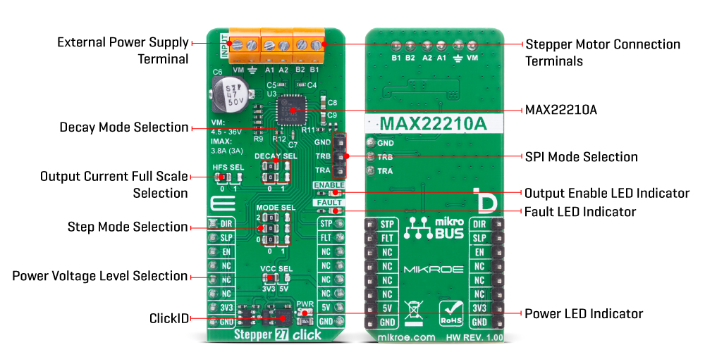
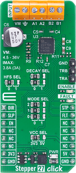
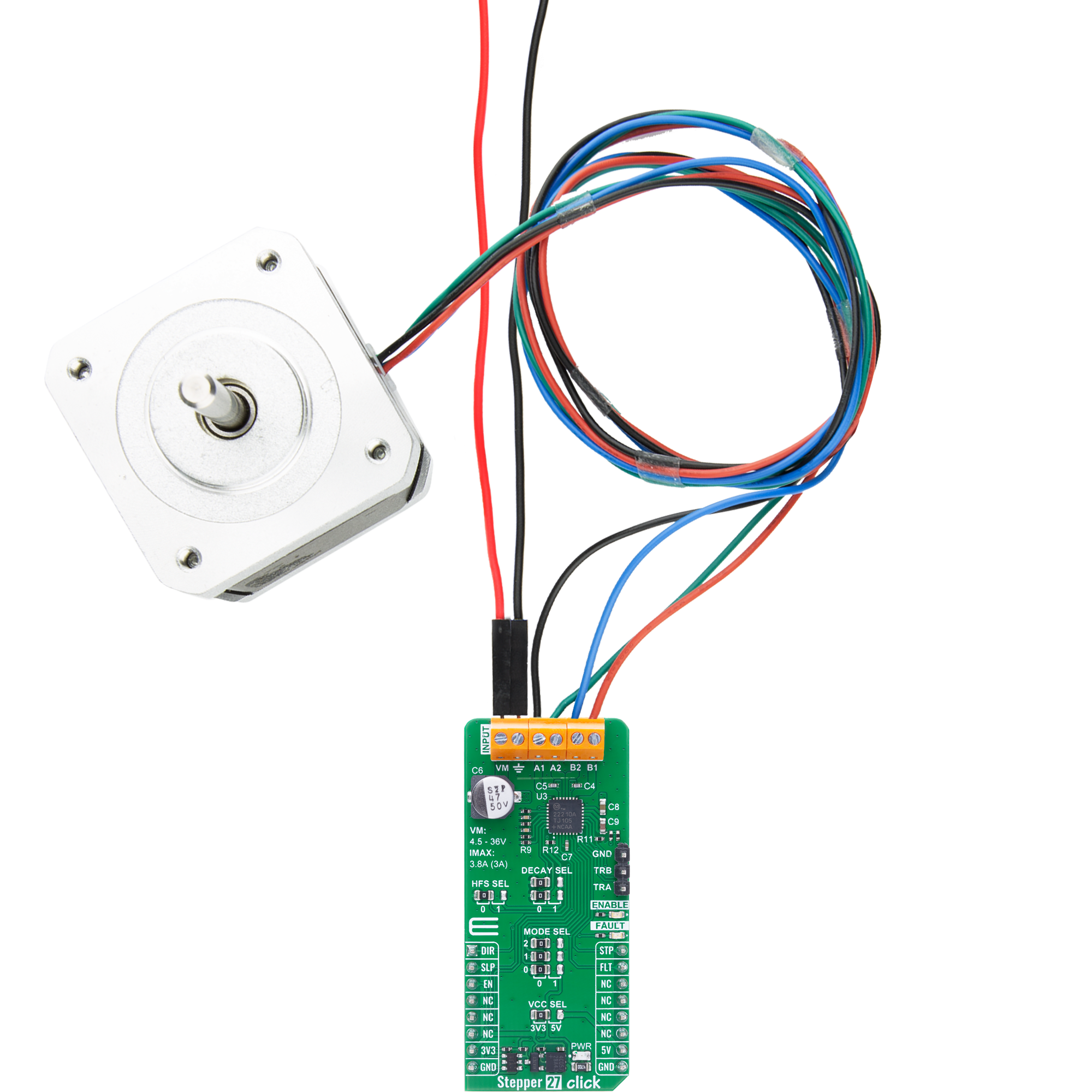
Stepper 27 Click is based on the MAX22210, a 2-phase stepper motor driver from Analog Devices. This highly integrated driver includes two low-impedance H-bridges with a typical total RON of just 0.25Ω (high side + low side), resulting in minimal power dissipation and efficient motor operation. The device incorporates an accurate current regulation system combined with a 128-microstep indexer that is controlled via a standard STEP/DIR interface, using the STP and DIR pins on the mikroBUS™ socket, and further configurable through MODE SEL jumpers. This advanced control logic enables smooth, quiet motor motion and makes it an ideal choice for precision motion applications. The current through the motor is monitored using non-dissipative Integrated Current Sensing (ICS) on the low-side FETs, which is compared to a programmed threshold. Once the current exceeds this threshold, the MAX22210 activates a decay phase using one of three selectable decay modes: slow, mixed, or adaptive. These decay modes are user-configurable through
DECAY SEL jumpers, offering flexibility depending on the motor and load behavior. The board is powered from an external power supply via the VM terminal and supports a wide input voltage range from 4.5V to 36V. It delivers up to 3.8A of impulsive current for small capacitive loads, or up to 3A full-scale regulated current with built-in overcurrent protection to safeguard the driver and motor. For use cases requiring high precision at lower currents - typically under 1.5A - the HFS SEL jumper can be configured to halve the full-scale current limit, doubling the low-side FET resistance and thus improving current control accuracy at the lower end of the range. Stepper 27 Click also includes robust fault protection features, such as thermal shutdown (TSD), undervoltage lockout (UVLO), and overcurrent protection. The SLP pin enables low-power Sleep mode by shutting down all internal biasing and outputs, while the EN pin controls the activation of the motor outputs. Fault detection is handled via the FLT pin, which is open-drain and active-low, and is triggered in response to thermal,
undervoltage, or overcurrent conditions. Visual feedback is provided by two onboard LEDs: a red FAULT LED and a yellow ENABLE LED, corresponding to FLT and EN pins respectively. Additionally, the MAX22210 provides two open-drain TRIGA and TRIGB output signals, which can be used to trigger external ADCs for synchronized current measurements. These TRIGx signals reflect the internal PWM activity and can be used for real-time diagnostics such as detecting motor stalls or abnormal stepper behavior, offering valuable insight into the driver’s performance during operation. This Click board™ can operate with either 3.3V or 5V logic voltage levels selected via the VCC SEL jumper. This way, both 3.3V and 5V capable MCUs can use the communication lines properly. Also, this Click board™ comes equipped with a library containing easy-to-use functions and an example code that can be used as a reference for further development.
Features overview
Development board
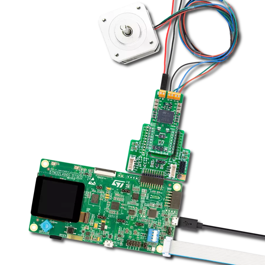
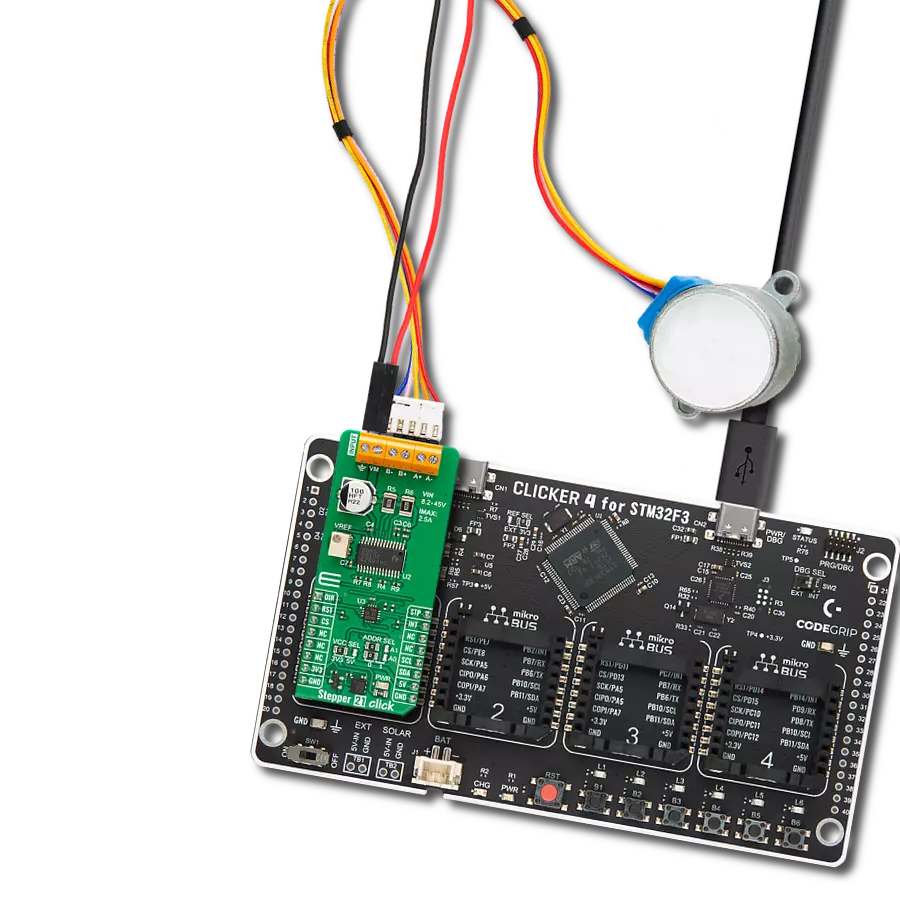
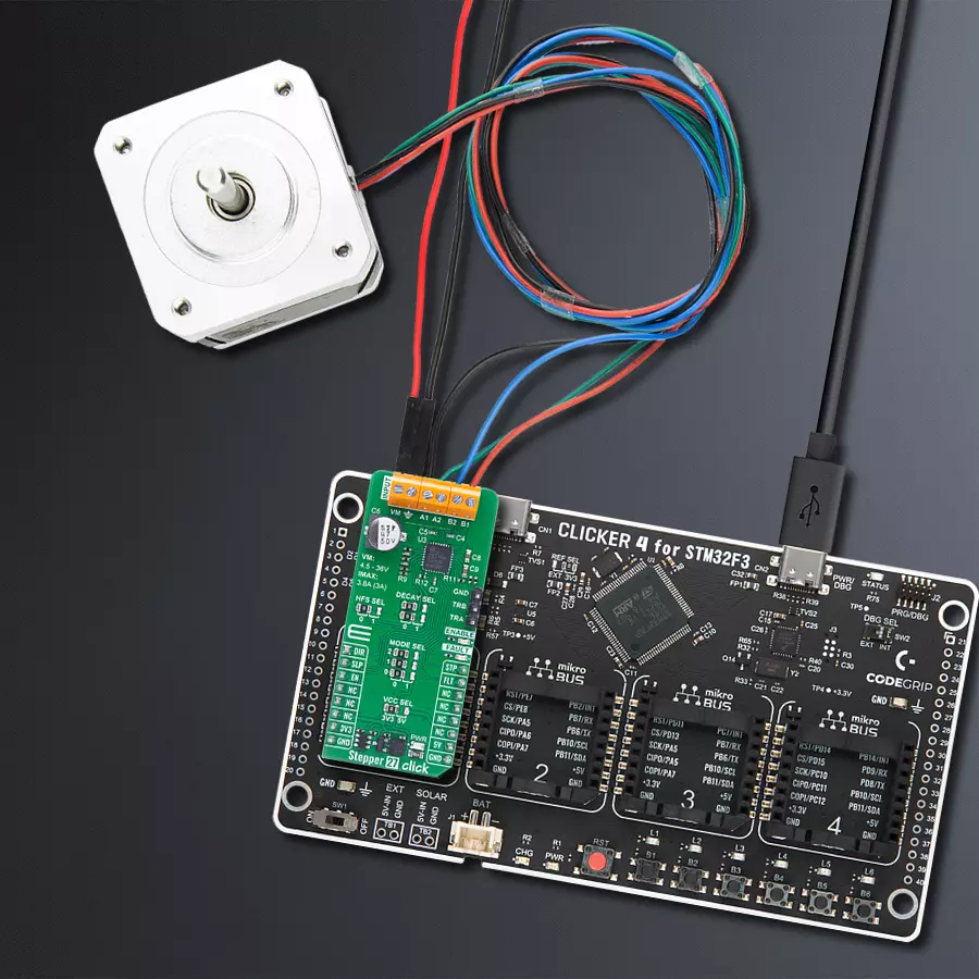
Clicker 4 for STM32F3 is a compact development board designed as a complete solution, you can use it to quickly build your own gadgets with unique functionalities. Featuring a STM32F302VCT6, four mikroBUS™ sockets for Click boards™ connectivity, power managment, and more, it represents a perfect solution for the rapid development of many different types of applications. At its core, there is a STM32F302VCT6 MCU, a powerful microcontroller by STMicroelectronics, based on the high-
performance Arm® Cortex®-M4 32-bit processor core operating at up to 168 MHz frequency. It provides sufficient processing power for the most demanding tasks, allowing Clicker 4 to adapt to any specific application requirements. Besides two 1x20 pin headers, four improved mikroBUS™ sockets represent the most distinctive connectivity feature, allowing access to a huge base of Click boards™, growing on a daily basis. Each section of Clicker 4 is clearly marked, offering an intuitive and clean interface. This makes working with the development
board much simpler and thus, faster. The usability of Clicker 4 doesn’t end with its ability to accelerate the prototyping and application development stages: it is designed as a complete solution which can be implemented directly into any project, with no additional hardware modifications required. Four mounting holes [4.2mm/0.165”] at all four corners allow simple installation by using mounting screws. For most applications, a nice stylish casing is all that is needed to turn the Clicker 4 development board into a fully functional, custom design.

Microcontroller Overview
MCU Card / MCU

Architecture
ARM Cortex-M4
MCU Memory (KB)
256
Silicon Vendor
STMicroelectronics
Pin count
100
RAM (Bytes)
40960
You complete me!
Accessories
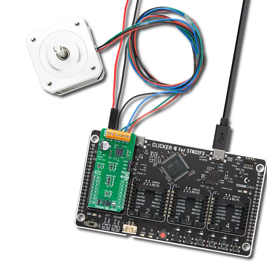
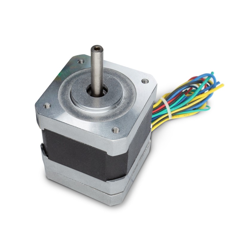
The 17HD40005-22B stepper motor is a two-phase hybrid motor for high torque, high speed, and low noise performance. It features a 1m wire with optional ports on the connection end and heat shrink tubing to prevent tangling. The motor's D-shaped axle is 22mm in length. This motor operates with a chopping wave constant current drive and has a two-phase 4-wire exciting mode, allowing for both forward and reverse rotation. The power order follows AB-BC-CD-DA, viewed as clockwise from the shaft end. It has a rated current of 1.3A DC, a rated voltage of 2.4V, and a stepping angle of 1.8°, with an insulation grade of B. This stepper motor is ideal for applications requiring precise movement control and reliability.
Used MCU Pins
mikroBUS™ mapper
Take a closer look
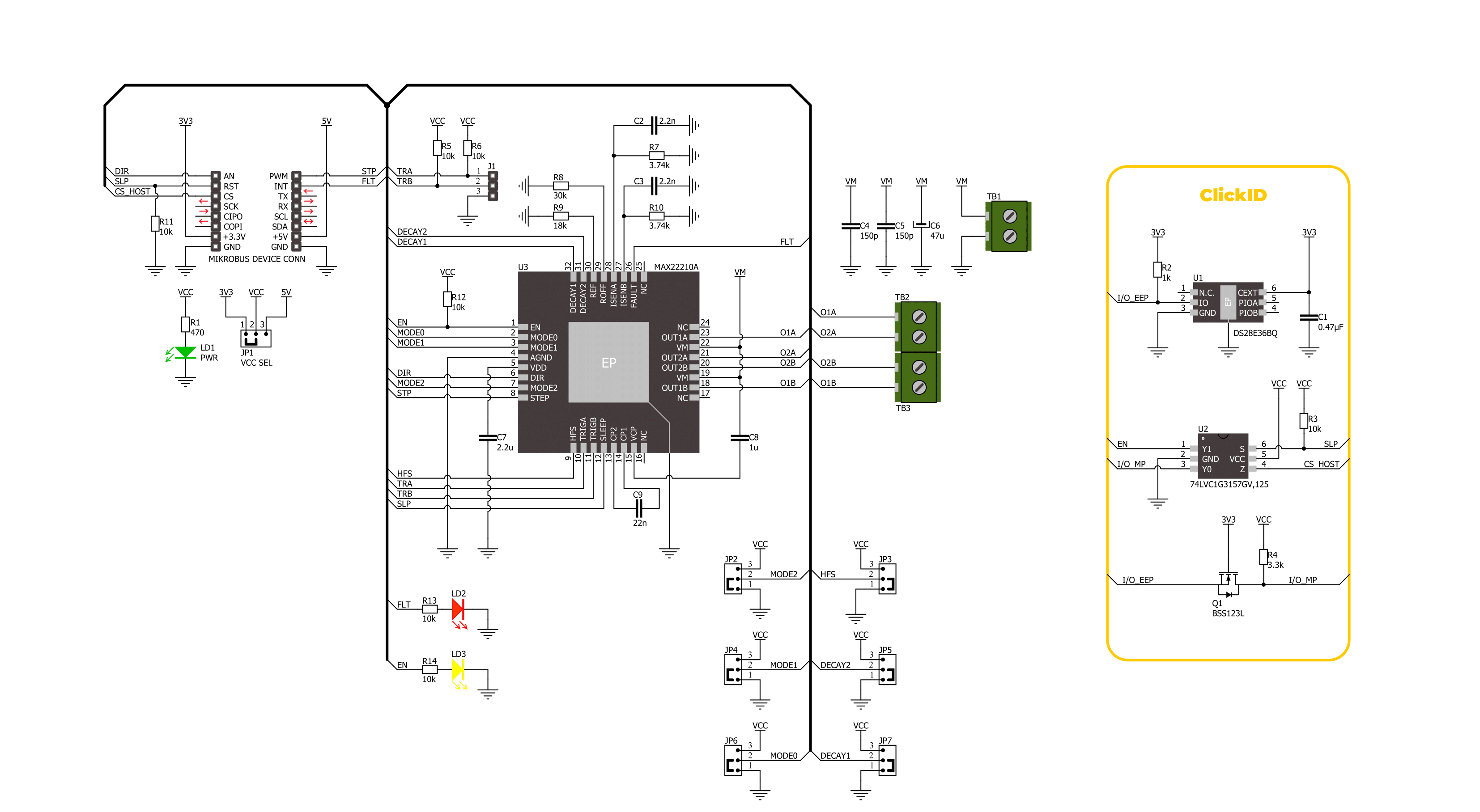
Click board™ Schematic
Step by step
Project assembly

Start by selecting your development board and Click board™. Begin with the CLICKER 4 for STM32F302VCT6 as your development board.


Track your results in real time
Application Output
1. Application Output - In Debug mode, the 'Application Output' window enables real-time data monitoring, offering direct insight into execution results. Ensure proper data display by configuring the environment correctly using the provided tutorial.

2. UART Terminal - Use the UART Terminal to monitor data transmission via a USB to UART converter, allowing direct communication between the Click board™ and your development system. Configure the baud rate and other serial settings according to your project's requirements to ensure proper functionality. For step-by-step setup instructions, refer to the provided tutorial.

3. Plot Output - The Plot feature offers a powerful way to visualize real-time sensor data, enabling trend analysis, debugging, and comparison of multiple data points. To set it up correctly, follow the provided tutorial, which includes a step-by-step example of using the Plot feature to display Click board™ readings. To use the Plot feature in your code, use the function: plot(*insert_graph_name*, variable_name);. This is a general format, and it is up to the user to replace 'insert_graph_name' with the actual graph name and 'variable_name' with the parameter to be displayed.

Software Support
Library Description
Stepper 27 Click demo application is developed using the NECTO Studio, ensuring compatibility with mikroSDK's open-source libraries and tools. Designed for plug-and-play implementation and testing, the demo is fully compatible with all development, starter, and mikromedia boards featuring a mikroBUS™ socket.
Example Description
This example demonstrates the use of the Stepper 27 Click board by driving the motor in both directions for a desired number of steps.
Key functions:
stepper27_cfg_setup- This function initializes Click configuration structure to initial values.stepper27_init- This function initializes all necessary pins and peripherals used for this Click board.stepper27_set_direction- This function sets the motor direction by setting the DIR pin logic state.stepper27_drive_motor- This function drives the motor for the specific number of steps at the selected speed.
Application Init
Initializes the driver and resets the device.
Application Task
Drives the motor clockwise for 100 slow steps and 300 medium speed steps and then counter-clockwise for 400 fast steps with a 1 second delay on driving mode change. All data is being logged on the USB UART where you can track the program flow.
Open Source
Code example
The complete application code and a ready-to-use project are available through the NECTO Studio Package Manager for direct installation in the NECTO Studio. The application code can also be found on the MIKROE GitHub account.
/*!
 * @file main.c
 * @brief Stepper 27 Click Example.
 *
 * # Description
 * This example demonstrates the use of the Stepper 27 Click board by driving the
 * motor in both directions for a desired number of steps.
 *
 * The demo application is composed of two sections :
 *
 * ## Application Init
 * Initializes the driver and resets the device.
 *
 * ## Application Task
 * Drives the motor clockwise for 100 slow steps and 300 medium speed steps and
 * then counter-clockwise for 400 fast steps with a 1 second delay on driving mode change.
 * All data is being logged on the USB UART where you can track the program flow.
 *
 * @author Stefan Filipovic
 *
 */

#include "board.h"
#include "log.h"
#include "stepper27.h"

static stepper27_t stepper27;
static log_t logger;

void application_init ( void )
{
    log_cfg_t log_cfg;  /**< Logger config object. */
    stepper27_cfg_t stepper27_cfg;  /**< Click config object. */

    /**
     * Logger initialization.
     * Default baud rate: 115200
     * Default log level: LOG_LEVEL_DEBUG
     * @note If USB_UART_RX and USB_UART_TX
     * are defined as HAL_PIN_NC, you will
     * need to define them manually for log to work.
     * See @b LOG_MAP_USB_UART macro definition for detailed explanation.
     */
    LOG_MAP_USB_UART( log_cfg );
    log_init( &logger, &log_cfg );
    log_info( &logger, " Application Init " );

    // Click initialization.
    stepper27_cfg_setup( &stepper27_cfg );
    STEPPER27_MAP_MIKROBUS( stepper27_cfg, MIKROBUS_1 );
    if ( DIGITAL_OUT_UNSUPPORTED_PIN == stepper27_init( &stepper27, &stepper27_cfg ) )
    {
        log_error( &logger, " Communication init." );
        for ( ; ; );
    }

    stepper27_reset_device ( &stepper27 );

    log_info( &logger, " Application Task " );
}

void application_task ( void )
{
    log_printf ( &logger, " Move 100 steps clockwise, speed: slow\r\n\n" );
    stepper27_set_direction ( &stepper27, STEPPER27_DIR_CW );
    stepper27_drive_motor ( &stepper27, 100, STEPPER27_SPEED_SLOW );
    Delay_ms ( 1000 );

    log_printf ( &logger, " Move 300 steps clockwise, speed: medium\r\n\n" );
    stepper27_set_direction ( &stepper27, STEPPER27_DIR_CW );
    stepper27_drive_motor ( &stepper27, 300, STEPPER27_SPEED_MEDIUM );
    Delay_ms ( 1000 );

    log_printf ( &logger, " Move 400 steps counter-clockwise, speed: fast\r\n\n" );
    stepper27_set_direction ( &stepper27, STEPPER27_DIR_CCW );
    stepper27_drive_motor ( &stepper27, 400, STEPPER27_SPEED_FAST );
    Delay_ms ( 1000 );
}

int main ( void )
{
    /* Do not remove this line or clock might not be set correctly. */
    #ifdef PREINIT_SUPPORTED
    preinit();
    #endif

    application_init( );

    for ( ; ; )
    {
        application_task( );
    }

    return 0;
}

// ------------------------------------------------------------------------ END
Additional Support
Resources
Category:Stepper