Connect devices across Europe with LTE Cat 1 communication using SIM7500E and PIC32MX470F512H
Reliable LTE connectivity for European IoT

Published Apr 02, 2025
Click board™
LTE Cat.1 8 Click
Dev. board
6LoWPAN clicker
Compiler
NECTO Studio
MCU
PIC32MX470F512H
Reliable LTE Cat 1 connectivity perfect for telematics, industrial routers, and remote diagnostics
A
A
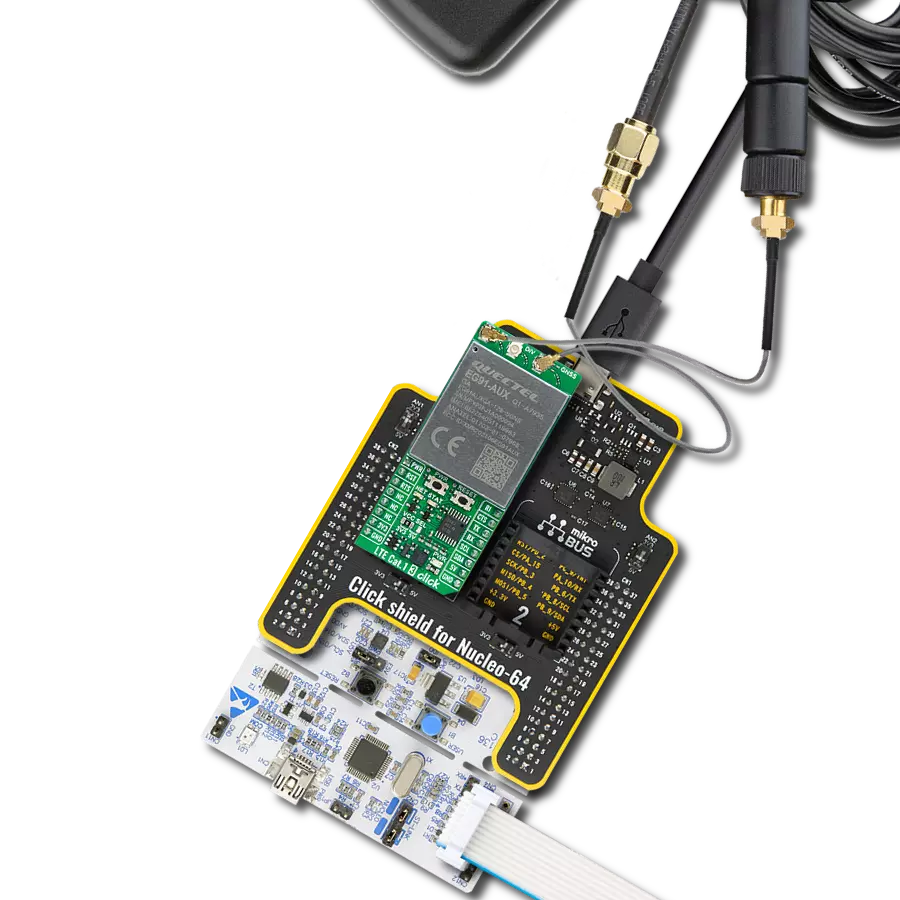
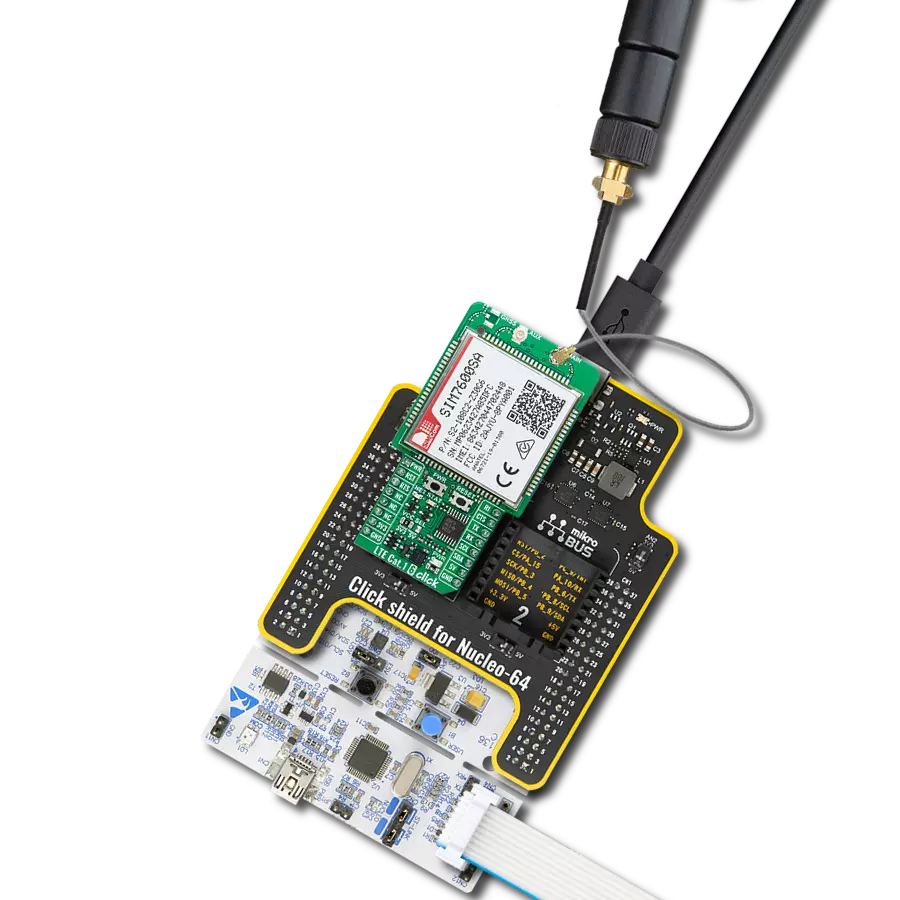
Hardware Overview
How does it work?
LTE Cat.1 8 Click is based on the SIM7500E, LTE Cat 1 module from SIMCom. This module enables LTE Category 1 communication and is capable of operating across various wireless standards including LTE-TDD, LTE-FDD, HSPA+, GSM, GPRS, and EDGE. Its compatibility with LTE, UMTS, and GSM networks ensures broad global coverage, making it ideal for applications that require dependable mobile connectivity across different regions. Its frequency band compatibility includes LTE-FDD on bands B1, B3, B7, B8, and B20, as well as GSM on 900 and 1800 MHz, enabling the device to adapt to multiple carrier networks efficiently. Designed for IoT scenarios like telematics, remote monitoring, CPE systems, industrial routers, and remote diagnostics, the LTE Cat.1 8 Click stands out as a reliable platform for developers seeking stable and versatile mobile communication in embedded systems. With support for download speeds of up to 10Mbps and upload speeds of up to 5Mbps, the SIM7500E provides a balanced data throughput suitable for a wide range of IoT use cases. In addition to its robust cellular communication capabilities, the module also features advanced location services through integrated multi-constellation GNSS support, ensuring high-accuracy positioning using various satellite systems. The SIM7500E also comes equipped with an array of embedded network protocols, including TCP/IP, IPv4, IPv6, Multi-PDP, FTP, FTPS, HTTP, HTTPS, and DNS, providing a comprehensive solution for secure and flexible data transmission. Furthermore, it supports USB drivers across major operating systems such as Windows,
Linux, and Android, allowing integration into diverse development environments. Communication between the SIM7500E and the host MCU is made through a UART interface, using standard UART RX and TX pins and hardware flow control pins (CTS/RTS/RI - Clear to Send/Ready to Send/Ring Indicator) for data transfer. The module defaults to a communication speed of 115200bps, allowing for data exchange over AT commands. This Click board™ also includes a USB Type C connector for both power and data transfer, which is compliant with the USB 2.0 specification (peripheral only), I2C interface only for read/write register values of the I2C peripheral devices, a BOOT switch on the back of the board to manage firmware upgrades (0 for normal operation, 1 for USB download), and FLIGHT switch for switching the board between Normal (1) and Flight (0) operation mode. The LTE Cat.1 8 Click includes several additional functionalities that enhance its usability and control. The PWR button allows users to easily power the module ON or OFF, while the RESET button provides a quick way to reset the module. These functions can also be controlled digitally via the mikroBUS™ pins PWR and RST, offering greater flexibility. Moreover, these controls have dedicated test points for easier debugging and testing. The board also features some visual indicators to provide real-time status updates. The first red NET LED indicates the module's current network status. When the LED is always on, the device searches for a network. A faster blinking pattern (200ms ON/OFF) indicates data transmission or 4G network registration. If the LED blinks slowly with
an 800ms ON/OFF pattern, the module is registered on a 2G or 3G network. When the LED is OFF, the device is powered OFF or sleep mode. The second yellow STAT LED indicates the module's power status, which stays off when the module is OFF and turns ON when the module is powered on. The board features three u.Fl connectors for LTE, Auxiliary-diversity, and optional GNSS antennas that MIKROE offers, like the GSM/GPRS antenna combined with an IPEX-SMA cable for flexible and efficient connectivity options. In addition, the user can easily choose the power supply of the optional GNSS antenna by choosing between 3.3V and 5V on the GNSS ANT jumper. However, please note that GNSS functionality is not currently supported on this Click board™, and as a result, GNSS-related components are not soldered. The board is equipped with a micro SIM card holder that supports both 1.8V and 3.0V uSIM cards, ensuring compatibility with a wide range of cellular networks and allowing users to select the most appropriate service provider for their particular use case. This Click board™ can operate with both 3.3V and 5V logic voltage levels selected via the VCC SEL jumper. Since the SIM7500E module operates at 3.8V, logic-level translators, the TXB0106 and PCA9306, are also used for proper operation and an accurate signal-level translation. This way, both 3.3V and 5V capable MCUs can use the communication lines properly. Also, this Click board™ comes equipped with a library containing easy-to-use functions and an example code that can be used as a reference for further development.

Features overview
Development board
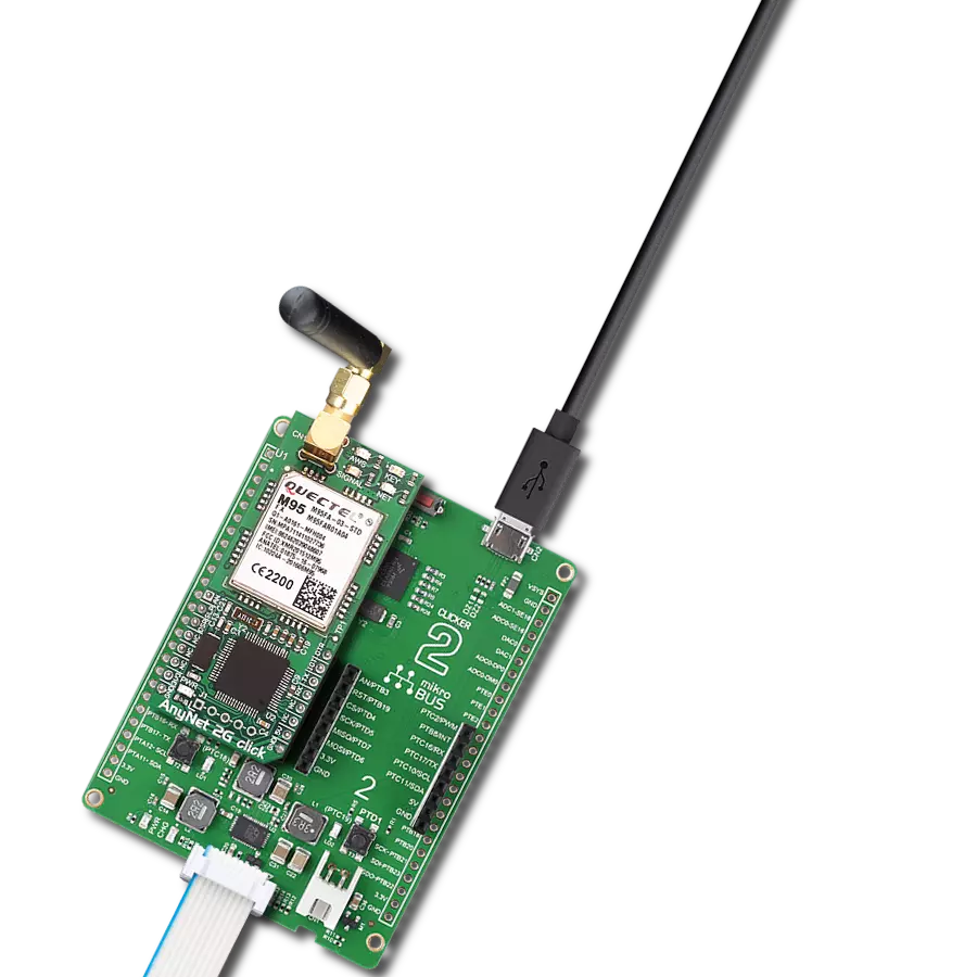
6LoWPAN Clicker is a compact starter development board that brings the flexibility of add-on Click boards™ to your favorite microcontroller, making it a perfect starter kit for implementing your ideas. It comes with an onboard 32-bit PIC microcontroller, the PIC32MX470F512H from Microchip, a USB connector, LED indicators, buttons, a mikroProg connector, and a header for interfacing with external electronics. Along with this microcontroller, the board also contains a 2.4GHz ISM band transceiver, allowing you to add wireless communication to your target application. Its compact design provides a fluid and immersive working experience, allowing access anywhere
and under any circumstances. Each part of the 6LoWPAN Clicker development kit contains the components necessary for the most efficient operation of the same board. In addition to the possibility of choosing the 6LoWPAN Clicker programming method, using USB HID mikroBootloader, or through an external mikroProg connector for PIC, dsPIC, or PIC32 programmer, the Clicker board also includes a clean and regulated power supply module for the development kit. The USB Micro-B connection can provide up to 500mA of current for the Clicker board, which is more than enough to operate all onboard and additional modules, or it can power
over two standard AA batteries. All communication methods that mikroBUS™ itself supports are on this board, including the well-established mikroBUS™ socket, reset button, and several buttons and LED indicators. 6LoWPAN Clicker is an integral part of the Mikroe ecosystem, allowing you to create a new application in minutes. Natively supported by Mikroe software tools, it covers many aspects of prototyping thanks to a considerable number of different Click boards™ (over a thousand boards), the number of which is growing every day.

Microcontroller Overview
MCU Card / MCU

Architecture
PIC32
MCU Memory (KB)
512
Silicon Vendor
Microchip
Pin count
64
RAM (Bytes)
131072
You complete me!
Accessories
Rubber Antenna GSM/GPRS Right Angle is the perfect companion for all GSM Click boards™ in our extensive lineup. This specialized antenna is designed to optimize your wireless connectivity with impressive features. With a wide frequency range spanning 824-894/1710-1990MHz or 890-960/1710-1890MHz, it can handle various frequency bands, ensuring a seamless and reliable connection. The antenna boasts an impedance of 50 Ohms and a gain of 2dB, enhancing signal reception and transmission. Its 70/180MHz bandwidth provides flexibility for diverse applications. The vertical polarization further enhances its performance. With a maximum input power capacity of 50W, this antenna ensures robust communication even under demanding conditions. Measuring a compact 50mm in length and featuring an SMA male connector, the Rubber Antenna GSM/GPRS Right Angle is a versatile and compact solution for your wireless communication needs.

Used MCU Pins
mikroBUS™ mapper
Take a closer look
Click board™ Schematic

Step by step
Project assembly

Start by selecting your development board and Click board™. Begin with the 6LoWPAN clicker as your development board.


Track your results in real time
Application Output
1. Application Output - In Debug mode, the 'Application Output' window enables real-time data monitoring, offering direct insight into execution results. Ensure proper data display by configuring the environment correctly using the provided tutorial.

2. UART Terminal - Use the UART Terminal to monitor data transmission via a USB to UART converter, allowing direct communication between the Click board™ and your development system. Configure the baud rate and other serial settings according to your project's requirements to ensure proper functionality. For step-by-step setup instructions, refer to the provided tutorial.

3. Plot Output - The Plot feature offers a powerful way to visualize real-time sensor data, enabling trend analysis, debugging, and comparison of multiple data points. To set it up correctly, follow the provided tutorial, which includes a step-by-step example of using the Plot feature to display Click board™ readings. To use the Plot feature in your code, use the function: plot(*insert_graph_name*, variable_name);. This is a general format, and it is up to the user to replace 'insert_graph_name' with the actual graph name and 'variable_name' with the parameter to be displayed.

Software Support
Library Description
LTE Cat.1 8 Click demo application is developed using the NECTO Studio, ensuring compatibility with mikroSDK's open-source libraries and tools. Designed for plug-and-play implementation and testing, the demo is fully compatible with all development, starter, and mikromedia boards featuring a mikroBUS™ socket.
Example Description
Application example shows device capability of connecting to the network and sending SMS or TCP/UDP messages using standard "AT" commands.
Key functions:
ltecat18_cfg_setup- This function initializes Click configuration structure to initial values.ltecat18_init- This function initializes all necessary pins and peripherals used for this Click board.ltecat18_set_sim_apn- This function sets APN for sim card.ltecat18_send_sms_text- This function sends text message to a phone number.ltecat18_cmd_set- This function sets a value to a specified command of the Click module.
Application Init
Initializes the driver and logger.
Application Task
Application task is split in few stages:
LTECAT18_POWER_UP:Powers up the device, performs a device factory reset and reads system information.LTECAT18_CONFIG_CONNECTION:Sets configuration to device to be able to connect to the network.LTECAT18_CHECK_CONNECTION:Waits for the network registration indicated via CEREG command and then checks the signal quality report.LTECAT18_CHECK_CONNECTION:Configures device for the selected example.LTECAT18_EXAMPLE:Depending on the selected demo example, it sends an SMS message (in PDU or TXT mode) or TCP/UDP message. By default, the TCP/UDP example is selected.
Open Source
Code example
The complete application code and a ready-to-use project are available through the NECTO Studio Package Manager for direct installation in the NECTO Studio. The application code can also be found on the MIKROE GitHub account.
/*!
* @file main.c
* @brief LTE Cat.1 8 Click Example.
*
* # Description
* Application example shows device capability of connecting to the network and
* sending SMS or TCP/UDP messages using standard "AT" commands.
*
* The demo application is composed of two sections :
*
* ## Application Init
* Initializes the driver and logger.
*
* ## Application Task
* Application task is split in few stages:
* - LTECAT18_POWER_UP:
* Powers up the device, performs a device factory reset and reads system information.
*
* - LTECAT18_CONFIG_CONNECTION:
* Sets configuration to device to be able to connect to the network.
*
* - LTECAT18_CHECK_CONNECTION:
* Waits for the network registration indicated via CREG command and then checks the signal quality report.
*
* - LTECAT18_CONFIG_EXAMPLE:
* Configures device for the selected example.
*
* - LTECAT18_EXAMPLE:
* Depending on the selected demo example, it sends an SMS message (in PDU or TXT mode) or TCP/UDP message.
*
* By default, the TCP/UDP example is selected.
*
* ## Additional Function
* - static void ltecat18_clear_app_buf ( void )
* - static void ltecat18_log_app_buf ( void )
* - static err_t ltecat18_process ( ltecat18_t *ctx )
* - static err_t ltecat18_read_response ( ltecat18_t *ctx, uint8_t *rsp )
* - static err_t ltecat18_power_up ( ltecat18_t *ctx )
* - static err_t ltecat18_config_connection ( ltecat18_t *ctx )
* - static err_t ltecat18_check_connection ( ltecat18_t *ctx )
* - static err_t ltecat18_config_example ( ltecat18_t *ctx )
* - static err_t ltecat18_example ( ltecat18_t *ctx )
*
* @note
* In order for the examples to work, user needs to set the APN and SMSC (SMS PDU mode only)
* of entered SIM card as well as the phone number (SMS mode only) to which he wants to send an SMS.
* Enter valid values for the following macros: SIM_APN, SIM_SMSC and PHONE_NUMBER.
* Example:
SIM_APN "internet"
SIM_SMSC "+381610401"
PHONE_NUMBER "+381659999999"
*
* @author Stefan Filipovic
*
*/
#include "board.h"
#include "log.h"
#include "ltecat18.h"
#include "conversions.h"
// Example selection macros
#define EXAMPLE_TCP_UDP 0 // Example of sending messages to a TCP/UDP echo server
#define EXAMPLE_SMS 1 // Example of sending SMS to a phone number
#define DEMO_EXAMPLE EXAMPLE_TCP_UDP // Example selection macro
// SIM APN config
#define SIM_APN "internet" // Set valid SIM APN
// SMS example parameters
#define SIM_SMSC "" // Set valid SMS Service Center Address - only in SMS PDU mode
#define PHONE_NUMBER "" // Set Phone number to message
#define SMS_MODE "1" // SMS mode: "0" - PDU, "1" - TXT
// TCP/UDP example parameters
#define REMOTE_IP "77.46.162.162" // TCP/UDP echo server IP address
#define REMOTE_PORT "51111" // TCP/UDP echo server port
// Message content
#define MESSAGE_CONTENT "LTE Cat.1 8 Click board - demo example."
// Application buffer size
#define APP_BUFFER_SIZE 256
#define PROCESS_BUFFER_SIZE 256
/**
* @brief Example states.
* @details Predefined enum values for application example state.
*/
typedef enum
{
LTECAT18_POWER_UP = 1,
LTECAT18_CONFIG_CONNECTION,
LTECAT18_CHECK_CONNECTION,
LTECAT18_CONFIG_EXAMPLE,
LTECAT18_EXAMPLE
} ltecat18_app_state_t;
/**
* @brief Application example variables.
* @details Variables used in application example.
*/
static uint8_t app_buf[ APP_BUFFER_SIZE ] = { 0 };
static int32_t app_buf_len = 0;
static ltecat18_app_state_t app_state = LTECAT18_POWER_UP;
static ltecat18_t ltecat18;
static log_t logger;
/**
* @brief LTE Cat.1 8 clearing application buffer.
* @details This function clears memory of application buffer and reset its length.
* @note None.
*/
static void ltecat18_clear_app_buf ( void );
/**
* @brief LTE Cat.1 8 log application buffer.
* @details This function logs data from application buffer to USB UART.
* @note None.
*/
static void ltecat18_log_app_buf ( void );
/**
* @brief LTE Cat.1 8 data reading function.
* @details This function reads data from device and concatenates data to application buffer.
* @param[in] ctx : Click context object.
* See #ltecat18_t object definition for detailed explanation.
* @return @li @c 0 - Read some data.
* @li @c -1 - Nothing is read.
* See #err_t definition for detailed explanation.
* @note None.
*/
static err_t ltecat18_process ( ltecat18_t *ctx );
/**
* @brief LTE Cat.1 8 read response function.
* @details This function waits for a response message, reads and displays it on the USB UART.
* @param[in] ctx : Click context object.
* See #ltecat18_t object definition for detailed explanation.
* @param[in] rsp Expected response.
* @return @li @c 0 - OK response.
* @li @c -2 - Timeout error.
* @li @c -3 - Command error.
* See #err_t definition for detailed explanation.
* @note None.
*/
static err_t ltecat18_read_response ( ltecat18_t *ctx, uint8_t *rsp );
/**
* @brief LTE Cat.1 8 power up function.
* @details This function powers up the device, performs device factory reset and reads system information.
* @param[in] ctx : Click context object.
* See #ltecat18_t object definition for detailed explanation.
* @return @li @c 0 - OK.
* @li @c != 0 - Read response error.
* See #err_t definition for detailed explanation.
* @note None.
*/
static err_t ltecat18_power_up ( ltecat18_t *ctx );
/**
* @brief LTE Cat.1 8 config connection function.
* @details This function configures and enables connection to the specified network.
* @param[in] ctx : Click context object.
* See #ltecat18_t object definition for detailed explanation.
* @return @li @c 0 - OK.
* @li @c != 0 - Read response error.
* See #err_t definition for detailed explanation.
* @note None.
*/
static err_t ltecat18_config_connection ( ltecat18_t *ctx );
/**
* @brief LTE Cat.1 8 check connection function.
* @details This function checks the connection to network.
* @param[in] ctx : Click context object.
* See #ltecat18_t object definition for detailed explanation.
* @return @li @c 0 - OK.
* @li @c != 0 - Read response error.
* See #err_t definition for detailed explanation.
* @note None.
*/
static err_t ltecat18_check_connection ( ltecat18_t *ctx );
/**
* @brief LTE Cat.1 8 config example function.
* @details This function configures device for the selected example.
* @param[in] ctx : Click context object.
* See #ltecat18_t object definition for detailed explanation.
* @return @li @c 0 - OK.
* @li @c != 0 - Read response error.
* See #err_t definition for detailed explanation.
* @note None.
*/
static err_t ltecat18_config_example ( ltecat18_t *ctx );
/**
* @brief LTE Cat.1 8 example function.
* @details This function executes SMS or TCP/UDP example depending on the DEMO_EXAMPLE macro.
* @param[in] ctx : Click context object.
* See #ltecat18_t object definition for detailed explanation.
* @return @li @c 0 - OK.
* @li @c != 0 - Read response error.
* See #err_t definition for detailed explanation.
* @note None.
*/
static err_t ltecat18_example ( ltecat18_t *ctx );
void application_init ( void )
{
log_cfg_t log_cfg; /**< Logger config object. */
ltecat18_cfg_t ltecat18_cfg; /**< Click config object. */
/**
* Logger initialization.
* Default baud rate: 115200
* Default log level: LOG_LEVEL_DEBUG
* @note If USB_UART_RX and USB_UART_TX
* are defined as HAL_PIN_NC, you will
* need to define them manually for log to work.
* See @b LOG_MAP_USB_UART macro definition for detailed explanation.
*/
LOG_MAP_USB_UART( log_cfg );
log_init( &logger, &log_cfg );
log_info( &logger, " Application Init " );
// Click initialization.
ltecat18_cfg_setup( <ecat18_cfg );
LTECAT18_MAP_MIKROBUS( ltecat18_cfg, MIKROBUS_1 );
if ( UART_ERROR == ltecat18_init( <ecat18, <ecat18_cfg ) )
{
log_error( &logger, " Communication init." );
for ( ; ; );
}
log_info( &logger, " Application Task " );
app_state = LTECAT18_POWER_UP;
log_printf( &logger, ">>> APP STATE - POWER UP <<<\r\n\n" );
}
void application_task ( void )
{
switch ( app_state )
{
case LTECAT18_POWER_UP:
{
if ( LTECAT18_OK == ltecat18_power_up( <ecat18 ) )
{
app_state = LTECAT18_CONFIG_CONNECTION;
log_printf( &logger, ">>> APP STATE - CONFIG CONNECTION <<<\r\n\n" );
}
break;
}
case LTECAT18_CONFIG_CONNECTION:
{
if ( LTECAT18_OK == ltecat18_config_connection( <ecat18 ) )
{
app_state = LTECAT18_CHECK_CONNECTION;
log_printf( &logger, ">>> APP STATE - CHECK CONNECTION <<<\r\n\n" );
}
break;
}
case LTECAT18_CHECK_CONNECTION:
{
if ( LTECAT18_OK == ltecat18_check_connection( <ecat18 ) )
{
app_state = LTECAT18_CONFIG_EXAMPLE;
log_printf( &logger, ">>> APP STATE - CONFIG EXAMPLE <<<\r\n\n" );
}
break;
}
case LTECAT18_CONFIG_EXAMPLE:
{
if ( LTECAT18_OK == ltecat18_config_example( <ecat18 ) )
{
app_state = LTECAT18_EXAMPLE;
log_printf( &logger, ">>> APP STATE - EXAMPLE <<<\r\n\n" );
}
break;
}
case LTECAT18_EXAMPLE:
{
ltecat18_example( <ecat18 );
break;
}
default:
{
log_error( &logger, " APP STATE." );
break;
}
}
}
int main ( void )
{
/* Do not remove this line or clock might not be set correctly. */
#ifdef PREINIT_SUPPORTED
preinit();
#endif
application_init( );
for ( ; ; )
{
application_task( );
}
return 0;
}
static void ltecat18_clear_app_buf ( void )
{
memset( app_buf, 0, app_buf_len );
app_buf_len = 0;
}
static void ltecat18_log_app_buf ( void )
{
for ( int32_t buf_cnt = 0; buf_cnt < app_buf_len; buf_cnt++ )
{
log_printf( &logger, "%c", app_buf[ buf_cnt ] );
}
}
static err_t ltecat18_process ( ltecat18_t *ctx )
{
uint8_t rx_buf[ PROCESS_BUFFER_SIZE ] = { 0 };
int32_t overflow_bytes = 0;
int32_t rx_cnt = 0;
int32_t rx_size = ltecat18_generic_read( ctx, rx_buf, PROCESS_BUFFER_SIZE );
if ( ( rx_size > 0 ) && ( rx_size <= APP_BUFFER_SIZE ) )
{
if ( ( app_buf_len + rx_size ) > APP_BUFFER_SIZE )
{
overflow_bytes = ( app_buf_len + rx_size ) - APP_BUFFER_SIZE;
app_buf_len = APP_BUFFER_SIZE - rx_size;
memmove ( app_buf, &app_buf[ overflow_bytes ], app_buf_len );
memset ( &app_buf[ app_buf_len ], 0, overflow_bytes );
}
for ( rx_cnt = 0; rx_cnt < rx_size; rx_cnt++ )
{
if ( rx_buf[ rx_cnt ] )
{
app_buf[ app_buf_len++ ] = rx_buf[ rx_cnt ];
}
}
return LTECAT18_OK;
}
return LTECAT18_ERROR;
}
static err_t ltecat18_read_response ( ltecat18_t *ctx, uint8_t *rsp )
{
#define READ_RESPONSE_TIMEOUT_MS 120000
uint32_t timeout_cnt = 0;
ltecat18_clear_app_buf( );
ltecat18_process( ctx );
while ( ( 0 == strstr( app_buf, rsp ) ) &&
( 0 == strstr( app_buf, LTECAT18_RSP_ERROR ) ) )
{
ltecat18_process( ctx );
if ( timeout_cnt++ > READ_RESPONSE_TIMEOUT_MS )
{
ltecat18_log_app_buf( );
ltecat18_clear_app_buf( );
log_error( &logger, " Timeout!" );
return LTECAT18_ERROR_TIMEOUT;
}
Delay_ms( 1 );
}
Delay_ms ( 200 );
ltecat18_process( ctx );
ltecat18_log_app_buf( );
if ( strstr( app_buf, rsp ) )
{
log_printf( &logger, "--------------------------------\r\n" );
return LTECAT18_OK;
}
return LTECAT18_ERROR_CMD;
}
static err_t ltecat18_power_up ( ltecat18_t *ctx )
{
err_t error_flag = LTECAT18_OK;
uint8_t power_state = LTECAT18_POWER_STATE_OFF;
for ( ; ; )
{
ltecat18_process( ctx );
ltecat18_log_app_buf( );
ltecat18_clear_app_buf( );
// Wake up UART interface
ltecat18_cmd_run( ctx, LTECAT18_CMD_AT );
log_printf( &logger, ">>> Check communication.\r\n" );
ltecat18_cmd_run( ctx, LTECAT18_CMD_AT );
if ( ( ( LTECAT18_OK == ltecat18_process( ctx ) ) && strstr( app_buf, LTECAT18_RSP_OK ) ) )
{
power_state = LTECAT18_POWER_STATE_ON;
break;
}
else if ( LTECAT18_POWER_STATE_OFF == power_state )
{
power_state = LTECAT18_POWER_STATE_ON;
log_printf( &logger, ">>> Power up device.\r\n" );
ltecat18_set_power_state ( ctx, power_state );
}
else if ( LTECAT18_POWER_STATE_ON == power_state )
{
power_state = LTECAT18_POWER_STATE_OFF;
log_printf( &logger, ">>> Power down device.\r\n" );
ltecat18_set_power_state ( ctx, power_state );
}
}
ltecat18_cmd_run( ctx, LTECAT18_CMD_AT );
error_flag |= ltecat18_read_response( ctx, LTECAT18_RSP_OK );
log_printf( &logger, ">>> Factory reset.\r\n" );
ltecat18_cmd_run( ctx, LTECAT18_CMD_FACTORY_RESET );
error_flag |= ltecat18_read_response( ctx, LTECAT18_RSP_OK );
log_printf( &logger, ">>> Get device model ID.\r\n" );
ltecat18_cmd_run( ctx, LTECAT18_CMD_GET_MODEL_ID );
error_flag |= ltecat18_read_response( ctx, LTECAT18_RSP_OK );
log_printf( &logger, ">>> Get device software version ID.\r\n" );
ltecat18_cmd_run( ctx, LTECAT18_CMD_GET_SW_VERSION );
error_flag |= ltecat18_read_response( ctx, LTECAT18_RSP_OK );
log_printf( &logger, ">>> Get device serial number.\r\n" );
ltecat18_cmd_run( ctx, LTECAT18_CMD_GET_SERIAL_NUM );
error_flag |= ltecat18_read_response( ctx, LTECAT18_RSP_OK );
return error_flag;
}
static err_t ltecat18_config_connection ( ltecat18_t *ctx )
{
err_t error_flag = LTECAT18_OK;
#if ( ( DEMO_EXAMPLE == EXAMPLE_TCP_UDP ) || ( DEMO_EXAMPLE == EXAMPLE_SMS ) )
log_printf( &logger, ">>> Deregister from network.\r\n" );
#define DEREGISTER_FROM_NETWORK "2"
ltecat18_cmd_set( ctx, LTECAT18_CMD_OPERATOR_SELECTION, DEREGISTER_FROM_NETWORK );
error_flag |= ltecat18_read_response( ctx, LTECAT18_RSP_OK );
log_printf( &logger, ">>> Set SIM APN.\r\n" );
ltecat18_set_sim_apn( <ecat18, SIM_APN );
error_flag |= ltecat18_read_response( ctx, LTECAT18_RSP_OK );
log_printf( &logger, ">>> Enable full functionality.\r\n" );
#define FULL_FUNCTIONALITY "1"
ltecat18_cmd_set( ctx, LTECAT18_CMD_SET_PHONE_FUNCTIONALITY, FULL_FUNCTIONALITY );
error_flag |= ltecat18_read_response( ctx, LTECAT18_RSP_OK );
log_printf( &logger, ">>> Enable network registration.\r\n" );
#define ENABLE_REG "2"
ltecat18_cmd_set( ctx, LTECAT18_CMD_NETWORK_REGISTRATION, ENABLE_REG );
error_flag |= ltecat18_read_response( ctx, LTECAT18_RSP_OK );
log_printf( &logger, ">>> Set automatic registration.\r\n" );
#define AUTOMATIC_REGISTRATION "0"
ltecat18_cmd_set( ctx, LTECAT18_CMD_OPERATOR_SELECTION, AUTOMATIC_REGISTRATION );
error_flag |= ltecat18_read_response( ctx, LTECAT18_RSP_OK );
#endif
return error_flag;
}
static err_t ltecat18_check_connection ( ltecat18_t *ctx )
{
err_t error_flag = LTECAT18_OK;
#if ( ( DEMO_EXAMPLE == EXAMPLE_TCP_UDP ) || ( DEMO_EXAMPLE == EXAMPLE_SMS ) )
log_printf( &logger, ">>> Check network registration.\r\n" );
#define CONNECTED "+CREG: 2,1"
ltecat18_cmd_get( <ecat18, LTECAT18_CMD_NETWORK_REGISTRATION );
error_flag |= ltecat18_read_response( ctx, LTECAT18_RSP_OK );
if ( strstr( app_buf, CONNECTED ) )
{
Delay_ms ( 1000 );
log_printf( &logger, ">>> Check signal quality.\r\n" );
ltecat18_cmd_run( <ecat18, LTECAT18_CMD_SIGNAL_QUALITY_REPORT );
error_flag |= ltecat18_read_response( ctx, LTECAT18_RSP_OK );
}
else
{
error_flag = LTECAT18_ERROR;
Delay_ms ( 1000 );
Delay_ms ( 1000 );
}
#endif
return error_flag;
}
static err_t ltecat18_config_example ( ltecat18_t *ctx )
{
err_t error_flag = LTECAT18_OK;
#if ( DEMO_EXAMPLE == EXAMPLE_TCP_UDP )
log_printf( &logger, ">>> Activate PDP context.\r\n" );
#define ACTIVATE_PDP_CONTEXT "1,1"
ltecat18_cmd_set( <ecat18, LTECAT18_CMD_ACTIVATE_PDP_CONTEXT, ACTIVATE_PDP_CONTEXT );
error_flag |= ltecat18_read_response( ctx, LTECAT18_RSP_OK );
log_printf( &logger, ">>> Show PDP address.\r\n" );
#define PDP_CID "1"
ltecat18_cmd_set( <ecat18, LTECAT18_CMD_SHOW_PDP_ADDRESS, PDP_CID );
error_flag |= ltecat18_read_response( ctx, LTECAT18_RSP_OK );
log_printf( &logger, ">>> Start TCPIP service.\r\n" );
ltecat18_cmd_run( <ecat18, LTECAT18_CMD_START_TCPIP_SERVICE );
error_flag |= ltecat18_read_response( ctx, LTECAT18_RSP_OK );
log_printf( &logger, ">>> Set RX mode to manually.\r\n" );
#define RX_MODE_MANUALLY "1"
ltecat18_cmd_set( <ecat18, LTECAT18_CMD_RECEIVE_DATA_VIA_CONNECTION, RX_MODE_MANUALLY );
error_flag |= ltecat18_read_response( ctx, LTECAT18_RSP_OK );
#elif ( DEMO_EXAMPLE == EXAMPLE_SMS )
log_printf( &logger, ">>> Select SMS format.\r\n" );
ltecat18_cmd_set( <ecat18, LTECAT18_CMD_SELECT_SMS_FORMAT, SMS_MODE );
error_flag |= ltecat18_read_response( ctx, LTECAT18_RSP_OK );
#endif
return error_flag;
}
static err_t ltecat18_example ( ltecat18_t *ctx )
{
err_t error_flag = LTECAT18_OK;
#if ( DEMO_EXAMPLE == EXAMPLE_TCP_UDP )
uint8_t cmd_buf[ 100 ] = { 0 };
log_printf( &logger, ">>> Open TCP connection.\r\n" );
#define TCP_LINK_NUM "0"
#define TCP_CONN_TYPE "TCP"
strcpy( cmd_buf, TCP_LINK_NUM );
strcat( cmd_buf, ",\"" );
strcat( cmd_buf, TCP_CONN_TYPE );
strcat( cmd_buf, "\",\"" );
strcat( cmd_buf, REMOTE_IP );
strcat( cmd_buf, "\"," );
strcat( cmd_buf, REMOTE_PORT );
ltecat18_cmd_set( <ecat18, LTECAT18_CMD_OPEN_TCP_UDP_CONNECTION, cmd_buf );
error_flag |= ltecat18_read_response( ctx, LTECAT18_URC_CONNECTION_OPEN );
log_printf( &logger, ">>> Open UDP connection.\r\n" );
#define UDP_LINK_NUM "1"
#define UDP_CONN_TYPE "UDP"
#define UDP_LOCAL_PORT "5000"
strcpy( cmd_buf, UDP_LINK_NUM );
strcat( cmd_buf, ",\"" );
strcat( cmd_buf, UDP_CONN_TYPE );
strcat( cmd_buf, "\",,," );
strcat( cmd_buf, UDP_LOCAL_PORT );
ltecat18_cmd_set( <ecat18, LTECAT18_CMD_OPEN_TCP_UDP_CONNECTION, cmd_buf );
error_flag |= ltecat18_read_response( ctx, LTECAT18_URC_CONNECTION_OPEN );
// Get message length
uint8_t message_len_buf[ 10 ] = { 0 };
uint16_t message_len = strlen( MESSAGE_CONTENT );
uint16_to_str( message_len, message_len_buf );
l_trim( message_len_buf );
r_trim( message_len_buf );
log_printf( &logger, ">>> Write message to TCP connection.\r\n" );
strcpy( cmd_buf, TCP_LINK_NUM );
strcat( cmd_buf, "," );
strcat( cmd_buf, message_len_buf );
ltecat18_cmd_set( <ecat18, LTECAT18_CMD_SEND_DATA_VIA_CONNECTION, cmd_buf );
Delay_ms ( 100 );
ltecat18_generic_write ( <ecat18, MESSAGE_CONTENT, message_len );
error_flag |= ltecat18_read_response( ctx, LTECAT18_URC_RECEIVED_DATA );
log_printf( &logger, ">>> Read response from TCP connection.\r\n" );
#define RX_DATA_READ "2"
strcpy( cmd_buf, RX_DATA_READ );
strcat( cmd_buf, "," );
strcat( cmd_buf, TCP_LINK_NUM );
strcat( cmd_buf, "," );
strcat( cmd_buf, message_len_buf );
ltecat18_cmd_set( <ecat18, LTECAT18_CMD_RECEIVE_DATA_VIA_CONNECTION, cmd_buf );
error_flag |= ltecat18_read_response( ctx, LTECAT18_RSP_OK );
log_printf( &logger, ">>> Write message to UDP connection.\r\n" );
strcpy( cmd_buf, UDP_LINK_NUM );
strcat( cmd_buf, "," );
strcat( cmd_buf, message_len_buf );
strcat( cmd_buf, ",\"" );
strcat( cmd_buf, REMOTE_IP );
strcat( cmd_buf, "\"," );
strcat( cmd_buf, REMOTE_PORT );
ltecat18_cmd_set( <ecat18, LTECAT18_CMD_SEND_DATA_VIA_CONNECTION, cmd_buf );
Delay_ms ( 100 );
ltecat18_generic_write ( <ecat18, MESSAGE_CONTENT, message_len );
error_flag |= ltecat18_read_response( ctx, LTECAT18_URC_RECEIVED_DATA );
log_printf( &logger, ">>> Read response from UDP connection.\r\n" );
strcpy( cmd_buf, RX_DATA_READ );
strcat( cmd_buf, "," );
strcat( cmd_buf, UDP_LINK_NUM );
strcat( cmd_buf, "," );
strcat( cmd_buf, message_len_buf );
ltecat18_cmd_set( <ecat18, LTECAT18_CMD_RECEIVE_DATA_VIA_CONNECTION, cmd_buf );
error_flag |= ltecat18_read_response( ctx, LTECAT18_RSP_OK );
log_printf( &logger, ">>> Close TCP connection.\r\n" );
ltecat18_cmd_set( <ecat18, LTECAT18_CMD_CLOSE_TCP_UDP_CONNECTION, TCP_LINK_NUM );
error_flag |= ltecat18_read_response( ctx, LTECAT18_URC_CONNECTION_CLOSED );
log_printf( &logger, ">>> Close UDP connection.\r\n" );
ltecat18_cmd_set( <ecat18, LTECAT18_CMD_CLOSE_TCP_UDP_CONNECTION, UDP_LINK_NUM );
error_flag |= ltecat18_read_response( ctx, LTECAT18_URC_CONNECTION_CLOSED );
Delay_ms ( 1000 );
Delay_ms ( 1000 );
Delay_ms ( 1000 );
Delay_ms ( 1000 );
Delay_ms ( 1000 );
#elif ( DEMO_EXAMPLE == EXAMPLE_SMS )
// Check SMS mode
#define CMGF_PDU "+CMGF: 0"
#define CMGF_TXT "+CMGF: 1"
log_printf( &logger, ">>> Check SMS format.\r\n" );
ltecat18_cmd_get( <ecat18, LTECAT18_CMD_SELECT_SMS_FORMAT );
error_flag |= ltecat18_read_response( ctx, LTECAT18_RSP_OK );
if ( strstr( app_buf, CMGF_PDU ) )
{
// Send SMS in PDU mode
log_printf( &logger, ">>> Send SMS in PDU mode.\r\n" );
ltecat18_send_sms_pdu( <ecat18, SIM_SMSC, PHONE_NUMBER, MESSAGE_CONTENT );
error_flag |= ltecat18_read_response( ctx, LTECAT18_RSP_OK );
}
else if ( strstr( app_buf, CMGF_TXT ) )
{
// Send SMS in TXT mode
log_printf( &logger, ">>> Send SMS in TXT mode.\r\n" );
ltecat18_send_sms_text ( <ecat18, PHONE_NUMBER, MESSAGE_CONTENT );
error_flag |= ltecat18_read_response( ctx, LTECAT18_RSP_OK );
}
// 30 seconds delay
for ( uint8_t delay_cnt = 0; delay_cnt < 30; delay_cnt++ )
{
Delay_ms ( 1000 );
}
#else
#error "No demo example selected"
#endif
return error_flag;
}
// ------------------------------------------------------------------------ END
Additional Support
Resources
Category:GSM/LTE