Zigbee 3.0 and BLE communication for long-range connectivity using XBRR-24Z8 and PIC32MX470F512H
Zigbee 3.0 mesh networking with indoor range of up to 60m and an outdoor line-of-sight range of up to 1200m

Published Feb 11, 2025
Click board™
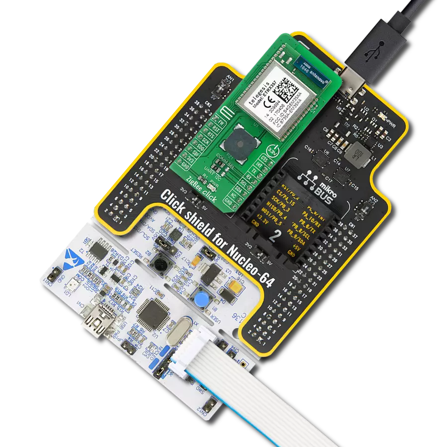
XBee 4 Click
Dev. board
6LoWPAN clicker
Compiler
NECTO Studio
MCU
PIC32MX470F512H
Zigbee 3.0 and BLE communication with long-range connectivity perfect for building automation, industrial monitoring, and smart energy management
A
A
Hardware Overview
How does it work?
XBee 4 Click is based on the XBRR-24Z8, a powerful Zigbee 3.0 module from DIGI International designed for wireless communication in various industrial and commercial applications. Operating within the 2.4GHz frequency range, this module integrates a Silicon Labs EFR32MG transceiver chipset, ensuring reliable data transmission. With a maximum RF data rate of 250Kbps and a serial communication speed of up to 1Mbps, it enables wireless connectivity across a wide range of smart applications. It supports Zigbee Mesh networking, providing connectivity for applications such as building automation, smart energy management, digital health solutions, and intelligent lighting systems. One of the key advantages of this module is its impressive communication range. Under optimal conditions with minimal interference, the indoor and urban range extends to 60 meters (200 feet), while the outdoor line-of-sight range reaches up to 1200 meters (4000 feet). Additionally, the module operates with a transmit power of +8dBm and a receiver sensitivity of -103dBm in normal mode, ensuring strong and stable signal reception even in challenging environments. Alongside Zigbee connectivity, it also supports Bluetooth® Low Energy (BLE) 4.2, allowing interoperability with BLE 5.0 devices that support the 1M PHY mode. In
BLE operation, the indoor range extends up to 15 meters (49 feet), while the outdoor line-of-sight range reaches 300 meters (984 feet), with a transmission power of +8dBm and a receiver sensitivity of -95dBm. The module has a 1MB flash memory and 96kB of RAM, providing ample storage for firmware and application data. Its compatibility with Zigbee 3.0 ensures full interoperability with a broad ecosystem of Zigbee-certified devices, making it an ideal solution for large-scale wireless networks. The module has received regulatory approvals in North America and Europe, allowing seamless deployment in multiple regions without additional certification requirements. This Click board™ achieves communication between the XBRR-24Z8 module and the host MCU through a UART interface, standard UART RX and TX pins, and hardware flow control via CTS and RTS pins. Additionally, it supports SPI communication (peripheral-only). The RTS pin is multiplexed with the SPI Chip Select (CS) pin on the SEL pin, allowing the selection of its function via the COM pin - set to 1 for RTS functionality or 0 for CS. By default, the UART communication speed is configured at 115200bps. Besides the interface pins, the board also uses a Sleep (SLP) pin (active high) for managing the module’s low-power mode
and a Reset (RST) pin (active low), allowing users to reset the module whenever necessary. This Click board™ also includes several LED indicators to provide real-time status feedback. The red ATT LED is an SPI attention indicator, signaling when the module requires SPI communication with the host MCU. The green ON LED serves as a device status indicator, confirming the operational state of the module. Additionally, the yellow ASC LED acts as an Associate indicator, working with the onboard commissioning button to simplify the deployment and integration of new Zigbee devices into an existing Zigbee network. The commissioning process enables network inclusion by configuring the device to communicate with other nodes, ensuring a stable and functional Zigbee mesh network. The board features one u.Fl connector for Sub-GHz antennas that MIKROE offers, like the 868MHz Straight Rubber Antenna, combined with an IPEX-SMA cable for flexible and efficient connectivity options. This Click board™ can be operated only with a 3.3V logic voltage level. The board must perform appropriate logic voltage level conversion before using MCUs with different logic levels. It also comes equipped with a library containing functions and example code that can be used as a reference for further development.

Features overview
Development board
6LoWPAN Clicker is a compact starter development board that brings the flexibility of add-on Click boards™ to your favorite microcontroller, making it a perfect starter kit for implementing your ideas. It comes with an onboard 32-bit PIC microcontroller, the PIC32MX470F512H from Microchip, a USB connector, LED indicators, buttons, a mikroProg connector, and a header for interfacing with external electronics. Along with this microcontroller, the board also contains a 2.4GHz ISM band transceiver, allowing you to add wireless communication to your target application. Its compact design provides a fluid and immersive working experience, allowing access anywhere
and under any circumstances. Each part of the 6LoWPAN Clicker development kit contains the components necessary for the most efficient operation of the same board. In addition to the possibility of choosing the 6LoWPAN Clicker programming method, using USB HID mikroBootloader, or through an external mikroProg connector for PIC, dsPIC, or PIC32 programmer, the Clicker board also includes a clean and regulated power supply module for the development kit. The USB Micro-B connection can provide up to 500mA of current for the Clicker board, which is more than enough to operate all onboard and additional modules, or it can power
over two standard AA batteries. All communication methods that mikroBUS™ itself supports are on this board, including the well-established mikroBUS™ socket, reset button, and several buttons and LED indicators. 6LoWPAN Clicker is an integral part of the Mikroe ecosystem, allowing you to create a new application in minutes. Natively supported by Mikroe software tools, it covers many aspects of prototyping thanks to a considerable number of different Click boards™ (over a thousand boards), the number of which is growing every day.

Microcontroller Overview
MCU Card / MCU

Architecture
PIC32
MCU Memory (KB)
512
Silicon Vendor
Microchip
Pin count
64
RAM (Bytes)
131072
You complete me!
Accessories
868MHz right-angle rubber antenna is a compact and versatile solution for wireless communication. Operating within the frequency range of 868-915MHz, it ensures optimal signal reception and transmission. With a 50-ohm impedance, it's compatible with various devices and systems. This antenna boasts a 2dB gain, enhancing signal strength and extending communication range. Its vertical polarization further contributes to signal clarity. Designed to handle up to 50W of input power, it's a robust choice for various applications. Measuring just 48mm in length, this antenna is both discreet and practical. Its SMA male connector ensures a secure and reliable connection to your equipment. Whether you're working with IoT devices, remote sensors, or other wireless technologies, the 868MHz right-angle antenna offers the performance and flexibility you need for seamless communication.

IPEX-SMA cable is a type of RF (radio frequency) cable assembly. "IPEX" refers to the IPEX connector, a miniature coaxial connector commonly used in small electronic devices. "SMA" stands for SubMiniature Version A and is another coaxial connector commonly used in RF applications. An IPEX-SMA cable assembly has an IPEX connector on one end and an SMA connector on the other, allowing it to connect devices or components that use these specific connectors. These cables are often used in applications like WiFi or cellular antennas, GPS modules, and other RF communication systems where a reliable and low-loss connection is required.

Used MCU Pins
mikroBUS™ mapper
Take a closer look
Click board™ Schematic

Step by step
Project assembly

Start by selecting your development board and Click board™. Begin with the 6LoWPAN clicker as your development board.


Track your results in real time
Application Output
1. Application Output - In Debug mode, the 'Application Output' window enables real-time data monitoring, offering direct insight into execution results. Ensure proper data display by configuring the environment correctly using the provided tutorial.

2. UART Terminal - Use the UART Terminal to monitor data transmission via a USB to UART converter, allowing direct communication between the Click board™ and your development system. Configure the baud rate and other serial settings according to your project's requirements to ensure proper functionality. For step-by-step setup instructions, refer to the provided tutorial.

3. Plot Output - The Plot feature offers a powerful way to visualize real-time sensor data, enabling trend analysis, debugging, and comparison of multiple data points. To set it up correctly, follow the provided tutorial, which includes a step-by-step example of using the Plot feature to display Click board™ readings. To use the Plot feature in your code, use the function: plot(*insert_graph_name*, variable_name);. This is a general format, and it is up to the user to replace 'insert_graph_name' with the actual graph name and 'variable_name' with the parameter to be displayed.

Software Support
Library Description
XBee 4 Click demo application is developed using the NECTO Studio, ensuring compatibility with mikroSDK's open-source libraries and tools. Designed for plug-and-play implementation and testing, the demo is fully compatible with all development, starter, and mikromedia boards featuring a mikroBUS™ socket.
Example Description
This example demonstrates the use of an XBee 4 Click by showing the communication between the two Click boards configured in transparent mode.
Key functions:
xbee4_cfg_setup- Config Object Initialization function.xbee4_init- Initialization function.xbee4_get_serial_number- This function sends a get serial number command.xbee4_set_device_name- This function sets the device name (node identifier).xbee4_set_destination_address- This function sets the destination address high and low bytes.
Application Init
Initializes the driver and configures the Click board by performing a factory reset, and setting the device name, destination address, api mode to transparent, and a device role to join or form network depending on the application mode.
Application Task
Depending on the selected application mode, it reads all the received data or sends the desired message every 3 seconds.
Open Source
Code example
The complete application code and a ready-to-use project are available through the NECTO Studio Package Manager for direct installation in the NECTO Studio. The application code can also be found on the MIKROE GitHub account.
/*!
 * @file main.c
 * @brief XBEE 4 Click Example.
 *
 * # Description
 * This example demonstrates the use of an XBEE 4 Click board by showing
 * the communication between the two Click boards configured in transparent mode.
 *
 * The demo application is composed of two sections :
 *
 * ## Application Init
 * Initializes the driver and configures the Click board by performing a factory reset,
 * and setting the device name, destination address, api mode to transparent,
 * and a device role to join or form network depending on the application mode.
 *
 * ## Application Task
 * Depending on the selected application mode, it reads all the received data or
 * sends the desired message every 3 seconds.
 *
 * ## Additional Function
 * - static void xbee4_clear_app_buf ( void )
 * - static void xbee4_log_app_buf ( void )
 * - static err_t xbee4_process ( xbee4_t *ctx )
 * - static err_t xbee4_read_response ( xbee4_t *ctx, uint8_t *rsp, uint32_t timeout )
 *
 * @author Stefan Filipovic
 *
 */

#include "board.h"
#include "log.h"
#include "xbee4.h"

// Device name (Node identifier).
#define DEVICE_NAME                 "XBEE 4 Click"

// Enter here the specific serial number high and low bytes of the remote device as a hex string or
// leave it set to broadcast addresses for forwarding messages to all devices
#define DESTINATION_ADDRESS_HIGH    XBEE4_BROADCAST_DEST_ADDRESS_HIGH
#define DESTINATION_ADDRESS_LOW     XBEE4_BROADCAST_DEST_ADDRESS_LOW

// Comment out the line below in order to switch the application mode to receiver
#define DEMO_APP_TRANSMITTER

// Text message to send in the transmitter application mode
#define DEMO_TEXT_MESSAGE           "MIKROE - XBEE 4 Click board\r\n"

// Application buffer size
#define APP_BUFFER_SIZE             400
#define PROCESS_BUFFER_SIZE         200

static xbee4_t xbee4;
static log_t logger;

static uint8_t app_buf[ APP_BUFFER_SIZE ] = { 0 };
static int32_t app_buf_len = 0;

/**
 * @brief XBEE 4 clearing application buffer.
 * @details This function clears memory of application buffer and reset its length.
 * @note None.
 */
static void xbee4_clear_app_buf ( void );

/**
 * @brief XBEE 4 log application buffer.
 * @details This function logs data from application buffer to USB UART.
 * @note None.
 */
static void xbee4_log_app_buf ( void );

/**
 * @brief XBEE 4 data reading function.
 * @details This function reads data from device and concatenates data to application buffer.
 * @param[in] ctx : Click context object.
 * See #xbee4_t object definition for detailed explanation.
 * @return @li @c  0 - Read some data.
 *         @li @c -1 - Nothing is read.
 * See #err_t definition for detailed explanation.
 * @note None.
 */
static err_t xbee4_process ( xbee4_t *ctx );

/**
 * @brief XBEE 4 read response function.
 * @details This function waits for a response message, reads and displays it on the USB UART.
 * @param[in] ctx : Click context object.
 * See #xbee4_t object definition for detailed explanation.
 * @param[in] rsp : Expected response.
 * @param[in] timeout : Response timeout in milliseconds.
 * @return @li @c  0 - OK response.
 *         @li @c -1 - Command error.
 *         @li @c -2 - Timeout error.
 * See #err_t definition for detailed explanation.
 * @note None.
 */
static err_t xbee4_read_response ( xbee4_t *ctx, uint8_t *rsp, uint32_t timeout );

void application_init ( void )
{
    log_cfg_t log_cfg;  /**< Logger config object. */
    xbee4_cfg_t xbee4_cfg;  /**< Click config object. */

    /**
     * Logger initialization.
     * Default baud rate: 115200
     * Default log level: LOG_LEVEL_DEBUG
     * @note If USB_UART_RX and USB_UART_TX
     * are defined as HAL_PIN_NC, you will
     * need to define them manually for log to work.
     * See @b LOG_MAP_USB_UART macro definition for detailed explanation.
     */
    LOG_MAP_USB_UART( log_cfg );
    log_init( &logger, &log_cfg );
    log_info( &logger, " Application Init " );

    // Click initialization.
    xbee4_cfg_setup( &xbee4_cfg );
    XBEE4_MAP_MIKROBUS( xbee4_cfg, MIKROBUS_1 );
    if ( UART_ERROR == xbee4_init( &xbee4, &xbee4_cfg ) )
    {
        log_error( &logger, " Communication init." );
        for ( ; ; );
    }

    xbee4_hw_reset ( &xbee4 );
    xbee4_process ( &xbee4 );
    xbee4_clear_app_buf( );

    log_printf( &logger, " - Enter command mode -\r\n" );
    xbee4_enter_command_mode ( &xbee4 );
    xbee4_read_response ( &xbee4, XBEE4_RSP_OK, XBEE4_TIMEOUT_3S );

    log_printf( &logger, " - Factory Reset -\r\n" );
    xbee4_factory_reset ( &xbee4 );
    xbee4_read_response ( &xbee4, XBEE4_RSP_OK, XBEE4_TIMEOUT_3S );

    log_printf( &logger, " - Get serial number -\r\n" );
    xbee4_get_serial_number ( &xbee4 );
    xbee4_read_response ( &xbee4, XBEE4_RSP_NEW_LINE, XBEE4_TIMEOUT_3S );

    log_printf( &logger, " - Set Device Name -\r\n" );
    xbee4_set_device_name ( &xbee4, DEVICE_NAME );
    xbee4_read_response ( &xbee4, XBEE4_RSP_OK, XBEE4_TIMEOUT_3S );

    log_printf( &logger, " - Set Destination Address -\r\n" );
    xbee4_set_destination_address ( &xbee4, DESTINATION_ADDRESS_HIGH, DESTINATION_ADDRESS_LOW );
    xbee4_read_response ( &xbee4, XBEE4_RSP_OK, XBEE4_TIMEOUT_3S );

    log_printf( &logger, " - Set API mode -\r\n" );
    xbee4_set_api_mode ( &xbee4, XBEE4_MODE_TRANSPARENT );
    xbee4_read_response ( &xbee4, XBEE4_RSP_OK, XBEE4_TIMEOUT_3S );

    log_printf( &logger, " - Set Device Role -\r\n" );
#ifdef DEMO_APP_TRANSMITTER
    xbee4_set_device_role ( &xbee4, XBEE4_DEVICE_ROLE_JOIN_NETWORK );
#else
    xbee4_set_device_role ( &xbee4, XBEE4_DEVICE_ROLE_FORM_NETWORK );
#endif
    xbee4_read_response ( &xbee4, XBEE4_RSP_OK, XBEE4_TIMEOUT_3S );

    log_printf( &logger, " - Apply changes -\r\n" );
    xbee4_apply_changes ( &xbee4 );
    xbee4_read_response ( &xbee4, XBEE4_RSP_OK, XBEE4_TIMEOUT_3S );

    log_printf( &logger, " - Save changes -\r\n" );
    xbee4_save_changes ( &xbee4 );
    xbee4_read_response ( &xbee4, XBEE4_RSP_OK, XBEE4_TIMEOUT_3S );

    log_printf( &logger, " - Exit command mode -\r\n" );
    xbee4_exit_command_mode ( &xbee4 );
    xbee4_read_response ( &xbee4, XBEE4_RSP_OK, XBEE4_TIMEOUT_3S );

    xbee4_clear_app_buf ( );

#ifdef DEMO_APP_TRANSMITTER
    log_printf( &logger, " Application Mode: Transmitter\r\n" );
#else
    log_printf( &logger, " Application Mode: Receiver\r\n" );
#endif

    log_info( &logger, " Application Task " );
}

void application_task ( void )
{
#ifdef DEMO_APP_TRANSMITTER
    xbee4_generic_write( &xbee4, DEMO_TEXT_MESSAGE, strlen( DEMO_TEXT_MESSAGE ) );
    log_printf( &logger, "%s", ( char * ) DEMO_TEXT_MESSAGE );
    Delay_ms ( 1000 );
    Delay_ms ( 1000 );
    Delay_ms ( 1000 );
#else
    if ( XBEE4_OK == xbee4_process( &xbee4 ) )
    {
        xbee4_log_app_buf ( );
        xbee4_clear_app_buf ( );
    }
#endif
}

int main ( void )
{
    /* Do not remove this line or clock might not be set correctly. */
    #ifdef PREINIT_SUPPORTED
    preinit();
    #endif

    application_init( );

    for ( ; ; )
    {
        application_task( );
    }

    return 0;
}

static void xbee4_clear_app_buf ( void )
{
    memset( app_buf, 0, app_buf_len );
    app_buf_len = 0;
}

static void xbee4_log_app_buf ( void )
{
    for ( int32_t buf_cnt = 0; buf_cnt < app_buf_len; buf_cnt++ )
    {
        log_printf( &logger, "%c", app_buf[ buf_cnt ] );
    }
}

static err_t xbee4_process ( xbee4_t *ctx )
{
    uint8_t rx_buf[ PROCESS_BUFFER_SIZE ] = { 0 };
    int32_t overflow_bytes = 0;
    int32_t rx_cnt = 0;
    int32_t rx_size = xbee4_generic_read( ctx, rx_buf, PROCESS_BUFFER_SIZE );
    if ( ( rx_size > 0 ) && ( rx_size <= APP_BUFFER_SIZE ) )
    {
        if ( ( app_buf_len + rx_size ) > APP_BUFFER_SIZE )
        {
            overflow_bytes = ( app_buf_len + rx_size ) - APP_BUFFER_SIZE;
            app_buf_len = APP_BUFFER_SIZE - rx_size;
            memmove ( app_buf, &app_buf[ overflow_bytes ], app_buf_len );
            memset ( &app_buf[ app_buf_len ], 0, overflow_bytes );
        }
        for ( rx_cnt = 0; rx_cnt < rx_size; rx_cnt++ )
        {
            if ( rx_buf[ rx_cnt ] )
            {
                app_buf[ app_buf_len++ ] = rx_buf[ rx_cnt ];
            }
        }
        return XBEE4_OK;
    }
    return XBEE4_ERROR;
}

static err_t xbee4_read_response ( xbee4_t *ctx, uint8_t *rsp, uint32_t timeout )
{
    uint32_t timeout_cnt = 0;
    xbee4_clear_app_buf ( );
    xbee4_process ( ctx );
    while ( ( 0 == strstr( app_buf, rsp ) ) &&
            ( 0 == strstr( app_buf, XBEE4_RSP_ERROR ) ) )
    {
        xbee4_process ( ctx );
        if ( timeout_cnt++ > timeout )
        {
            xbee4_log_app_buf( );
            log_error( &logger, " Timeout!" );
            return XBEE4_ERROR_TIMEOUT;
        }
        Delay_ms ( 1 );
    }
    Delay_ms ( 100 );
    xbee4_process( ctx );
    xbee4_log_app_buf( );
    if ( strstr( app_buf, XBEE4_RSP_ERROR ) )
    {
        log_error( &logger, " CMD!" );
        return XBEE4_ERROR;
    }
    log_printf( &logger, "--------------------------------\r\n" );
    return XBEE4_OK;
}

// ------------------------------------------------------------------------ END
Additional Support
Resources
Category:ZigBee