Add 10/100BASE-TX Ethernet connectivity to your embedded systems with XP100200S-05R and STM32F031K6
Compact and secure Ethernet connectivity solution for your embedded systems

Published Jun 17, 2025
Click board™
XPort ETH Click - SE
Dev. board
Nucleo 32 with STM32F031K6 MCU
Compiler
NECTO Studio
MCU
STM32F031K6
Add secure, encrypted Ethernet connectivity with integrated web server and TCP/IP stack
A
A
Hardware Overview
How does it work?
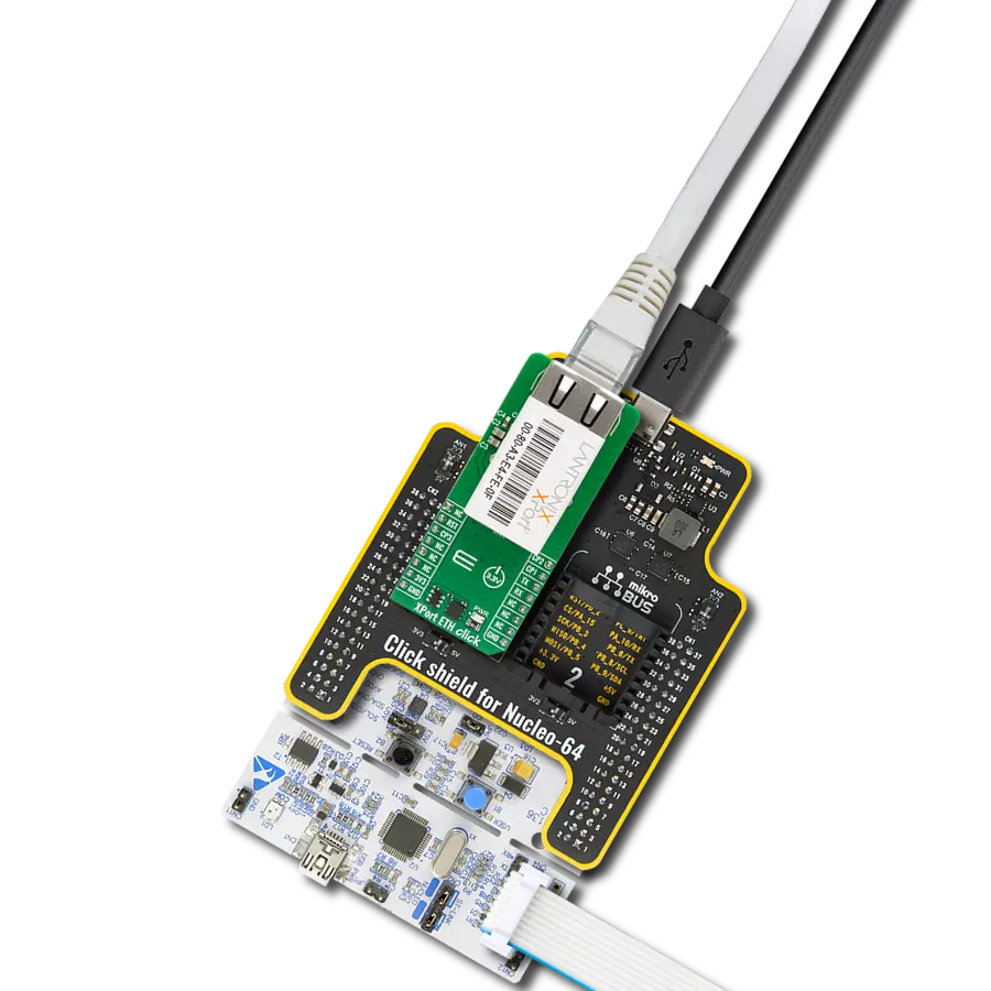
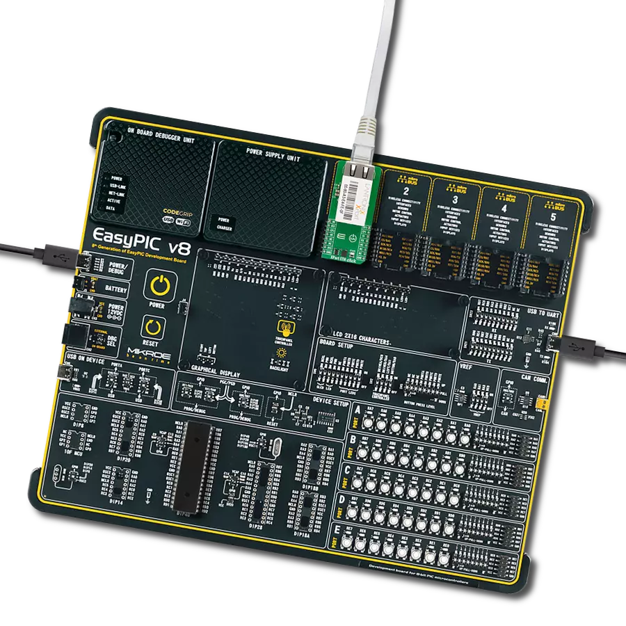
XPort ETH Click - SE is based on the XP100200S-05R XPort module from Lantronix, made for embedded systems requiring encrypted data transfer. The XP100200S-05R module extends the standard feature set with 256-bit AES encryption, enabling secure networking in sensitive applications. Compact and powerful, this module provides 10BASE-T/100BASE-TX Ethernet, embedded web server functionality, a complete TCP/IP protocol stack, and serial communication - all packed into an RJ45 Ethernet connector ideal for adding reliable Ethernet communication to a wide range of embedded applications. The XPort module is powered by the DSTni EX controller, which includes 256KB of SRAM, 16KB of boot ROM, and a built-in MAC with an integrated 10/100BASE-TX PHY. The processing core operates on 1.8V supplied by an internal regulator,
while the entire solution runs on a 3.3V power supply. A built-in voltage supervisory circuit ensures reliable operation by resetting the module if the supply voltage drops below 2.7V. Communication with the host device is achieved via UART interface and three configurable general-purpose I/O pins (CP1, CP2, and CP3), which can function as flow/modem control lines or general-purpose signals. In addition, the XPort includes 512KB of flash memory for storing firmware and web content, enabling full customization and remote management of connected devices. As mentioned, the module connects directly to an Ethernet network through the RJ45 port. Two bi-color LEDs integrated into the front of the connector provide real-time status indication. When both LEDs are off, there is no link or activity. The left LED (Link LED) glows amber for a 10Mbps connection and green
for 100Mbps. The right LED (Activity LED) indicates half-duplex mode with an amber light and full-duplex mode with green. XPort ETH Click - SE also benefits from simple electromechanical integration thanks to its compliance with Class B emissions standards. For configuration and control, it comes with Windows-based Device Installer software and a Com Port Redirector, supporting both x86 and x64 Windows platforms, including XP, Vista, Windows 7, Windows 8, 2003 Server, and 2008 Server. This Click board™ can be operated only with a 3.3V logic voltage level. The board must perform appropriate logic voltage level conversion before using MCUs with different logic levels. It also comes equipped with a library containing functions and example code that can be used as a reference for further development.

Features overview
Development board
Nucleo 32 with STM32F031K6 MCU board provides an affordable and flexible platform for experimenting with STM32 microcontrollers in 32-pin packages. Featuring Arduino™ Nano connectivity, it allows easy expansion with specialized shields, while being mbed-enabled for seamless integration with online resources. The
board includes an on-board ST-LINK/V2-1 debugger/programmer, supporting USB reenumeration with three interfaces: Virtual Com port, mass storage, and debug port. It offers a flexible power supply through either USB VBUS or an external source. Additionally, it includes three LEDs (LD1 for USB communication, LD2 for power,
and LD3 as a user LED) and a reset push button. The STM32 Nucleo-32 board is supported by various Integrated Development Environments (IDEs) such as IAR™, Keil®, and GCC-based IDEs like AC6 SW4STM32, making it a versatile tool for developers.

Microcontroller Overview
MCU Card / MCU

Architecture
ARM Cortex-M0
MCU Memory (KB)
32
Silicon Vendor
STMicroelectronics
Pin count
32
RAM (Bytes)
4096
You complete me!
Accessories
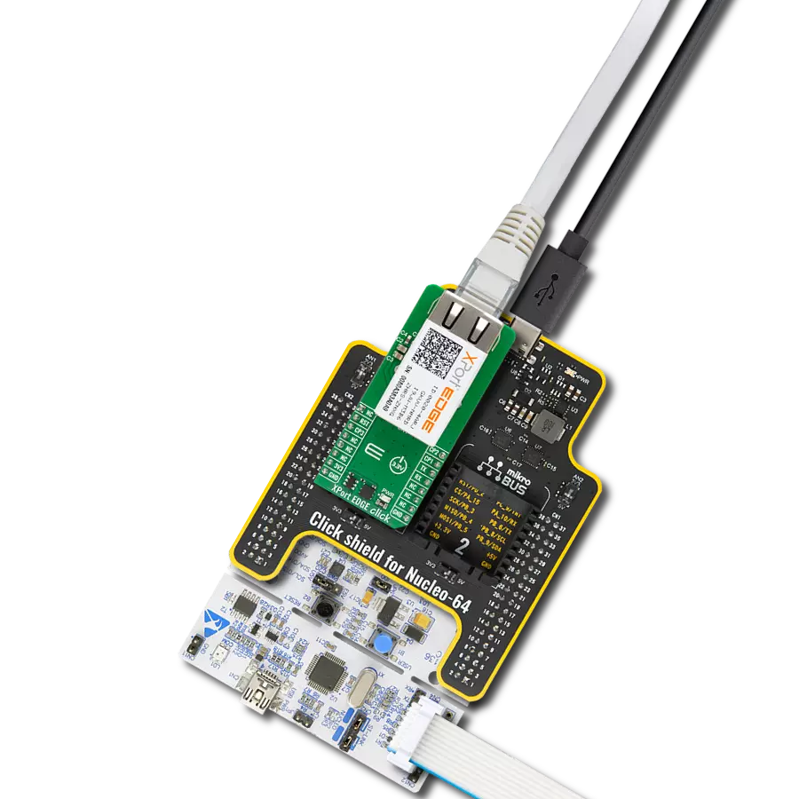
Click Shield for Nucleo-32 is the perfect way to expand your development board's functionalities with STM32 Nucleo-32 pinout. The Click Shield for Nucleo-32 provides two mikroBUS™ sockets to add any functionality from our ever-growing range of Click boards™. We are fully stocked with everything, from sensors and WiFi transceivers to motor control and audio amplifiers. The Click Shield for Nucleo-32 is compatible with the STM32 Nucleo-32 board, providing an affordable and flexible way for users to try out new ideas and quickly create prototypes with any STM32 microcontrollers, choosing from the various combinations of performance, power consumption, and features. The STM32 Nucleo-32 boards do not require any separate probe as they integrate the ST-LINK/V2-1 debugger/programmer and come with the STM32 comprehensive software HAL library and various packaged software examples. This development platform provides users with an effortless and common way to combine the STM32 Nucleo-32 footprint compatible board with their favorite Click boards™ in their upcoming projects.

RJ45 UTP (Unshielded Twisted Pair) cable is a widely used networking cable designed for Ethernet connections in both residential and commercial environments. It features an RJ45 connector at each end, allowing it to interface with routers, switches, computers, and other network devices. The UTP cable consists of four twisted pairs of copper wires, which help reduce electromagnetic interference without the need for additional shielding. These cables are categorized by performance levels, such as Cat5e, Cat6, and Cat6a, each supporting different speeds and bandwidths. Commonly used for wired internet access, data transfer, and VoIP systems, RJ45 UTP cables offer a reliable solution for high-speed network communication. Their plug-and-play design makes installation simple, while the twisted pair construction ensures signal integrity over medium distances. Ideal for structured cabling and LAN setups, RJ45 UTP cables remain a backbone component in modern networking infrastructure.

Used MCU Pins
mikroBUS™ mapper
Take a closer look
Click board™ Schematic

Step by step
Project assembly

Start by selecting your development board and Click board™. Begin with the Nucleo 32 with STM32F031K6 MCU as your development board.


Track your results in real time
Application Output
1. Application Output - In Debug mode, the 'Application Output' window enables real-time data monitoring, offering direct insight into execution results. Ensure proper data display by configuring the environment correctly using the provided tutorial.

2. UART Terminal - Use the UART Terminal to monitor data transmission via a USB to UART converter, allowing direct communication between the Click board™ and your development system. Configure the baud rate and other serial settings according to your project's requirements to ensure proper functionality. For step-by-step setup instructions, refer to the provided tutorial.

3. Plot Output - The Plot feature offers a powerful way to visualize real-time sensor data, enabling trend analysis, debugging, and comparison of multiple data points. To set it up correctly, follow the provided tutorial, which includes a step-by-step example of using the Plot feature to display Click board™ readings. To use the Plot feature in your code, use the function: plot(*insert_graph_name*, variable_name);. This is a general format, and it is up to the user to replace 'insert_graph_name' with the actual graph name and 'variable_name' with the parameter to be displayed.

Software Support
Library Description
XPort ETH Click - SE demo application is developed using the NECTO Studio, ensuring compatibility with mikroSDK's open-source libraries and tools. Designed for plug-and-play implementation and testing, the demo is fully compatible with all development, starter, and mikromedia boards featuring a mikroBUS™ socket.
Example Description
This example demonstrates the use of the XPort ETH Click - SE board for Ethernet communication. The application initializes the XPort ETH SE module, retrieves essential information such as firmware version, MAC address, and network status, and demonstrates sending a ping command. It also allows for bidirectional UART communication between the USB UART and the XPort ETH SE UART.
Key functions:
xportethse_cfg_setup- This function initializes Click configuration structure to initial values.xportethse_init- This function initializes all necessary pins and peripherals used for this Click board.xportethse_reset_device- This function resets device by toggling the RST pin state.xportethse_send_cmd- This function sends a command string by using UART serial interface.xportethse_send_enter- This function sends enter (new line) by using UART serial interface.
Application Init
Initializes the UART communication, logs essential information, configures the XPort ETH SE module, and retrieves the firmware version, MAC address, and network status. It also demonstrates basic command operations such as pinging the specific IP address (8.8.8.8).
Application Task
Continuously reads data from the USB UART and forwards it to the XPort ETH SE module, while also capturing responses from the module and forwarding them back to the USB UART. This allows real-time interaction with the device through the UART Terminal for configuration and diagnostics.
Open Source
Code example
The complete application code and a ready-to-use project are available through the NECTO Studio Package Manager for direct installation in the NECTO Studio. The application code can also be found on the MIKROE GitHub account.
/*!
 * @file main.c
 * @brief XPort ETH SE Click Example.
 *
 * # Description
 * This example demonstrates the use of the XPort ETH SE Click board for Ethernet communication.
 * The application initializes the XPort ETH SE module, retrieves essential information such as
 * firmware version, MAC address, and network status, and demonstrates sending a ping command.
 * It also allows for bidirectional UART communication between the USB UART and the XPort ETH SE UART.
 *
 * The demo application is composed of two sections :
 *
 * ## Application Init
 * Initializes the UART communication, logs essential information, configures the XPort ETH SE module,
 * and retrieves the firmware version, MAC address, and network status. It also demonstrates basic
 * command operations such as pinging the specific IP address (8.8.8.8).
 *
 * ## Application Task
 * Continuously reads data from the USB UART and forwards it to the XPort ETH SE module,
 * while also capturing responses from the module and forwarding them back to the USB UART.
 * This allows real-time interaction with the device through the UART Terminal for
 * configuration and diagnostics.
 *
 * ## Additional Function
 * - static void xportethse_clear_app_buf ( void )
 * - static err_t xportethse_process ( xportethse_t *ctx )
 * - static err_t xportethse_read_response ( xportethse_t *ctx )
 *
 * @note
 * Ensure the XPort ETH SE Click board is properly connected to the network.
 *
 * @author Stefan Filipovic
 *
 */

#include "board.h"
#include "log.h"
#include "xportethse.h"

// Application buffer size
#define APP_BUFFER_SIZE             300
#define PROCESS_BUFFER_SIZE         100

static xportethse_t xportethse;
static log_t logger;

static uint8_t app_buf[ APP_BUFFER_SIZE ] = { 0 };
static int32_t app_buf_len = 0;

/**
 * @brief XPort ETH SE clearing application buffer.
 * @details This function clears memory of application buffer and reset its length.
 * @note None.
 */
static void xportethse_clear_app_buf ( void );

/**
 * @brief XPort ETH SE data reading function.
 * @details This function reads data from device and concatenates data to application buffer.
 * @param[in] ctx : Click context object.
 * See #xportethse_t object definition for detailed explanation.
 * @return @li @c  0 - Read some data.
 *         @li @c -1 - Nothing is read.
 * See #err_t definition for detailed explanation.
 * @note None.
 */
static err_t xportethse_process ( xportethse_t *ctx );

/**
 * @brief XPort ETH SE read response function.
 * @details This function waits for a response message, reads and displays it on the USB UART.
 * @param[in] ctx : Click context object.
 * See #xportethse_t object definition for detailed explanation.
 * @return @li @c  0 - OK response.
 *         @li @c -2 - Timeout error.
 * See #err_t definition for detailed explanation.
 * @note None.
 */
static err_t xportethse_read_response ( xportethse_t *ctx );

void application_init ( void )
{
    log_cfg_t log_cfg;  /**< Logger config object. */
    xportethse_cfg_t xportethse_cfg;  /**< Click config object. */

    /**
     * Logger initialization.
     * Default baud rate: 115200
     * Default log level: LOG_LEVEL_DEBUG
     * @note If USB_UART_RX and USB_UART_TX
     * are defined as HAL_PIN_NC, you will
     * need to define them manually for log to work.
     * See @b LOG_MAP_USB_UART macro definition for detailed explanation.
     */
    LOG_MAP_USB_UART( log_cfg );
    log_init( &logger, &log_cfg );
    log_info( &logger, " Application Init " );

    // Click initialization.
    xportethse_cfg_setup( &xportethse_cfg );
    XPORTETHSE_MAP_MIKROBUS( xportethse_cfg, MIKROBUS_1 );
    if ( UART_ERROR == xportethse_init( &xportethse, &xportethse_cfg ) )
    {
        log_error( &logger, " Communication init." );
        for ( ; ; );
    }

    log_printf( &logger, ">>> Reset Device to Monitor Mode <<<\r\n" );
    xportethse_reset_device ( &xportethse );
    xportethse_send_enter ( &xportethse );
    xportethse_send_cmd ( &xportethse, XPORTETHSE_CMD_MODE_MONITOR_WITH_NET );
    xportethse_read_response ( &xportethse );

    log_printf( &logger, "\r\n-----------------------------\r\n" );
    log_printf( &logger, ">>> Query Firmware Version <<<\r\n" );
    xportethse_send_cmd ( &xportethse, XPORTETHSE_CMD_QUERY_FW_VERSION );
    xportethse_read_response ( &xportethse );

    log_printf( &logger, "\r\n-----------------------------\r\n" );
    log_printf( &logger, ">>> Get MAC Address <<<\r\n" );
    xportethse_send_cmd ( &xportethse, XPORTETHSE_CMD_GET_MAC_ADDRESS );
    xportethse_read_response ( &xportethse );

    log_printf( &logger, "\r\n-----------------------------\r\n" );
    log_printf( &logger, ">>> Get Network Status and IP Address <<<\r\n" );
    log_printf( &logger, ">>> Send QU Command to Exit Monitor Mode and Connect to Listed <<<\r\n" );
    log_printf( &logger, ">>> IP Address Through Web Browser to Access Web Interface <<<\r\n" );
    xportethse_send_cmd ( &xportethse, XPORTETHSE_CMD_NET_STAT );
    xportethse_read_response ( &xportethse );

    log_printf( &logger, "\r\n-----------------------------\r\n" );
    log_printf( &logger, ">>> Ping 8.8.8.8 and Switch to UART Terminal Commands Input <<<\r\n" );
    xportethse_send_cmd ( &xportethse, XPORTETHSE_CMD_PING( "8.8.8.8" ) );
    xportethse_send_enter ( &xportethse );
    xportethse_read_response ( &xportethse );
}

void application_task ( void )
{
    app_buf_len = uart_read( &logger.uart, app_buf, PROCESS_BUFFER_SIZE );
    if ( app_buf_len > 0 )
    {
        uart_write ( &xportethse.uart, app_buf, app_buf_len );
        xportethse_clear_app_buf ( );
    }
    app_buf_len = uart_read( &xportethse.uart, app_buf, PROCESS_BUFFER_SIZE );
    if ( app_buf_len > 0 )
    {
        uart_write ( &logger.uart, app_buf, app_buf_len );
        xportethse_clear_app_buf ( );
    }
}

int main ( void )
{
    /* Do not remove this line or clock might not be set correctly. */
    #ifdef PREINIT_SUPPORTED
    preinit();
    #endif

    application_init( );

    for ( ; ; )
    {
        application_task( );
    }

    return 0;
}

static void xportethse_clear_app_buf ( void )
{
    memset( app_buf, 0, app_buf_len );
    app_buf_len = 0;
}

static void xportethse_log_app_buf ( void )
{
    for ( int32_t buf_cnt = 0; buf_cnt < app_buf_len; buf_cnt++ )
    {
        log_printf( &logger, "%c", app_buf[ buf_cnt ] );
    }
}

static err_t xportethse_process ( xportethse_t *ctx )
{
    uint8_t rx_buf[ PROCESS_BUFFER_SIZE ] = { 0 };
    int32_t overflow_bytes = 0;
    int32_t rx_cnt = 0;
    int32_t rx_size = xportethse_generic_read( ctx, rx_buf, PROCESS_BUFFER_SIZE );
    if ( ( rx_size > 0 ) && ( rx_size <= APP_BUFFER_SIZE ) )
    {
        if ( ( app_buf_len + rx_size ) > APP_BUFFER_SIZE )
        {
            overflow_bytes = ( app_buf_len + rx_size ) - APP_BUFFER_SIZE;
            app_buf_len = APP_BUFFER_SIZE - rx_size;
            memmove ( app_buf, &app_buf[ overflow_bytes ], app_buf_len );
            memset ( &app_buf[ app_buf_len ], 0, overflow_bytes );
        }
        for ( rx_cnt = 0; rx_cnt < rx_size; rx_cnt++ )
        {
            if ( rx_buf[ rx_cnt ] )
            {
                app_buf[ app_buf_len++ ] = rx_buf[ rx_cnt ];
                log_printf( &logger, "%c", rx_buf[ rx_cnt ] );
            }
        }
        return XPORTETHSE_OK;
    }
    return XPORTETHSE_ERROR;
}

static err_t xportethse_read_response ( xportethse_t *ctx )
{
    uint32_t timeout_cnt = 0;
    uint32_t timeout = 30000;
    xportethse_clear_app_buf ( );
    while ( ( 0 == strstr( app_buf, XPORTETHSE_RSP_OK ) ) &&
            ( 0 == strstr( app_buf, XPORTETHSE_RSP_NO_ANSWER ) ) &&
            ( 0 == strstr( app_buf, XPORTETHSE_RSP_NO_REACH ) ) &&
            ( 0 == strstr( app_buf, XPORTETHSE_RSP_WRONG_PAR ) ) &&
            ( 0 == strstr( app_buf, XPORTETHSE_RSP_INVALID_CMD ) ) )
    {
        Delay_ms ( 1 );
        xportethse_process( ctx );
        if ( timeout_cnt++ > timeout )
        {
            return XPORTETHSE_ERROR_TIMEOUT;
        }
    }
    timeout_cnt = 0;
    timeout = 50;
    xportethse_clear_app_buf ( );
    while ( timeout_cnt++ < timeout )
    {
        if ( XPORTETHSE_OK == xportethse_process( ctx ) )
        {
            timeout_cnt = 0;
        }
        Delay_ms ( 1 );
    }
    xportethse_clear_app_buf ( );
    return XPORTETHSE_OK;
}

// ------------------------------------------------------------------------ END
Additional Support
Resources
Category:Ethernet