Upgrade UI experiences with a visual knob position indicator based on EC12D1564402 and STM32L496AG
Step into a world of precision and style
Published Jul 22, 2025
Click board™
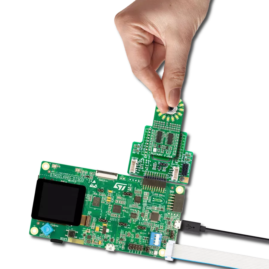
ROTARY Y Click
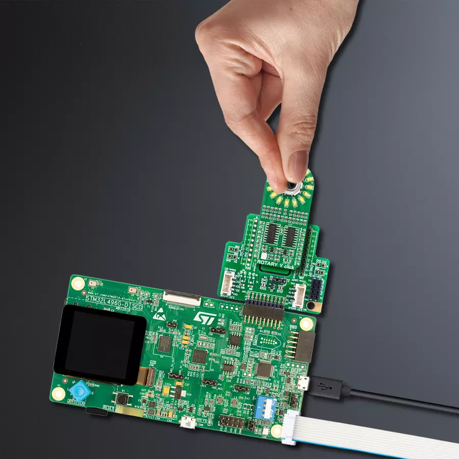
Dev. board
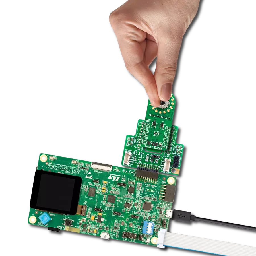
Discovery kit with STM32L496AG MCU
Compiler
NECTO Studio
MCU
STM32L496AG
Unveil a new era of control and sophistication with our exceptional rotary solution, embraced by a luminous yellow LED signature
A
A
Hardware Overview
How does it work?
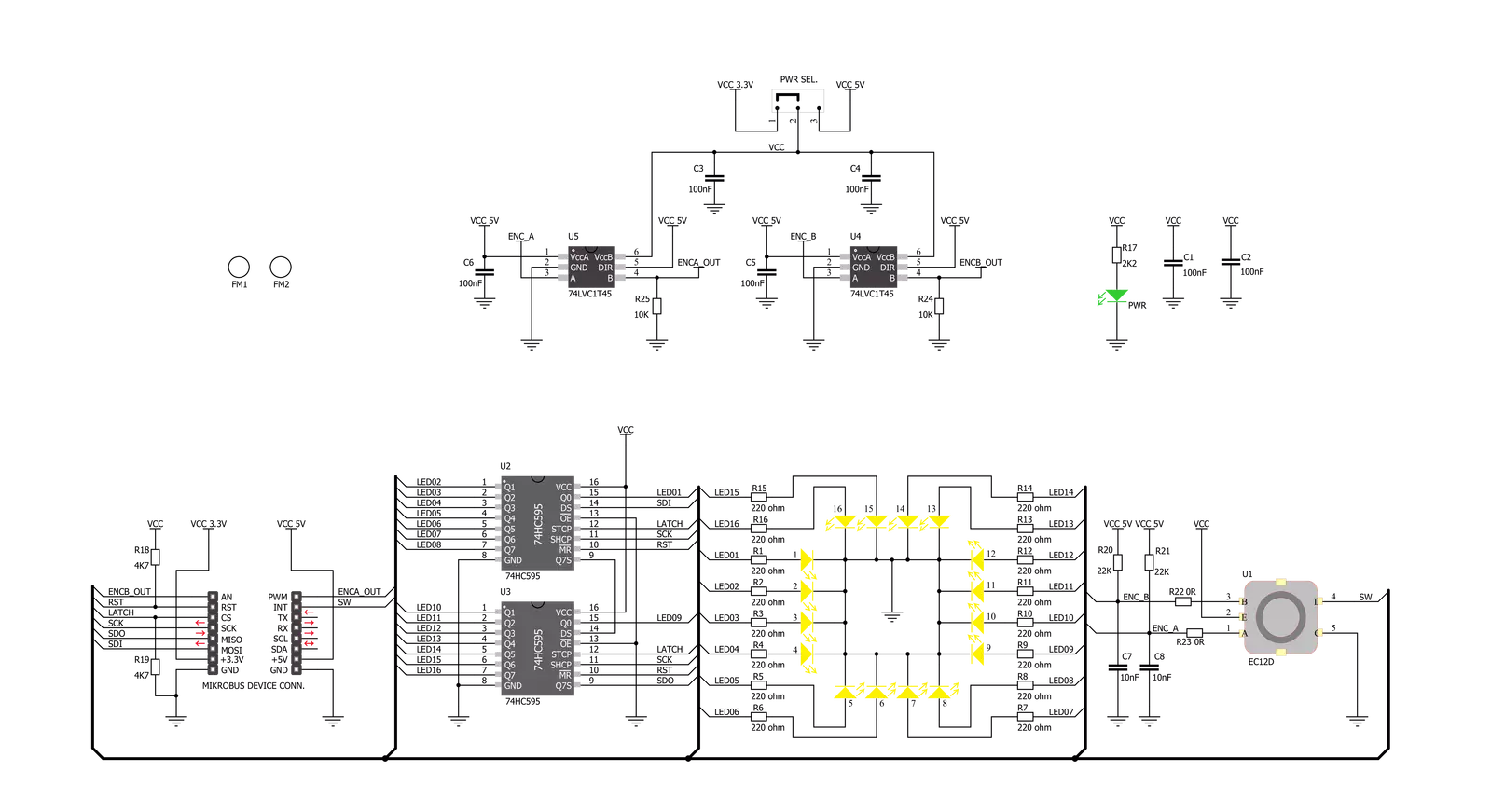
ROTARY Y Click is based on two SN74HC595 SPI-configurable 8-bit shift registers from Texas Instruments that, combined with a high-quality rotary encoder, the EC12D1564402, allows you to add a precision input knob to your design. The EC12D1564402 incremental rotary encoder is surrounded by a ring of 16 yellow LEDs where a single rotation is divided into 15 discrete steps (in contrast to a potentiometer, a rotary encoder can be spun around continuously). This Click board™ is an ideal solution for building various HMI applications where precise input is required, but also for some interesting visual effects to any application. As mentioned, this Click board™ uses
the EC12D1564402, a 15-pulse incremental rotary encoder with a push-button, from ALPS. This encoder has unique mechanical specifications (debouncing time for its internal switches goes down to 2ms) and can withstand many switching cycles, up to 30.000. The supporting debouncing circuitry allows contacts to settle before the output is triggered fully. The SN74HC595 controls each LED individually positioned in a ring around the encoder through a standard SPI interface with a maximum frequency of 5MHz. Rotating the encoder, it outputs A and B signals (out of phase to each other) on the two mikroBUS™ lines, AN and PWM pins of the mikroBUS™ socket,
alongside the push-button contact, which outputs through the interrupt line of the mikroBUS™ socket. The SN74HC595 also has a Reset feature used across the RST mikroBUS™ line. This Click board™ can operate with both 3.3V and 5V logic voltage levels selected via the PWR SEL jumper. This way, it is allowed for both 3.3V and 5V capable MCUs to use the communication lines properly. However, the Click board™ comes equipped with a library containing easy-to-use functions and an example code that can be used, as a reference, for further development.

Features overview
Development board
The 32L496GDISCOVERY Discovery kit serves as a comprehensive demonstration and development platform for the STM32L496AG microcontroller, featuring an Arm® Cortex®-M4 core. Designed for applications that demand a balance of high performance, advanced graphics, and ultra-low power consumption, this kit enables seamless prototyping for a wide range of embedded solutions. With its innovative energy-efficient
architecture, the STM32L496AG integrates extended RAM and the Chrom-ART Accelerator, enhancing graphics performance while maintaining low power consumption. This makes the kit particularly well-suited for applications involving audio processing, graphical user interfaces, and real-time data acquisition, where energy efficiency is a key requirement. For ease of development, the board includes an onboard ST-LINK/V2-1
debugger/programmer, providing a seamless out-of-the-box experience for loading, debugging, and testing applications without requiring additional hardware. The combination of low power features, enhanced memory capabilities, and built-in debugging tools makes the 32L496GDISCOVERY kit an ideal choice for prototyping advanced embedded systems with state-of-the-art energy efficiency.

Microcontroller Overview
MCU Card / MCU

Architecture
ARM Cortex-M4
MCU Memory (KB)
1024
Silicon Vendor
STMicroelectronics
Pin count
169
RAM (Bytes)
327680
Used MCU Pins
mikroBUS™ mapper
Take a closer look
Click board™ Schematic
Step by step
Project assembly

Start by selecting your development board and Click board™. Begin with the Discovery kit with STM32L496AG MCU as your development board.


Track your results in real time
Application Output
1. Application Output - In Debug mode, the 'Application Output' window enables real-time data monitoring, offering direct insight into execution results. Ensure proper data display by configuring the environment correctly using the provided tutorial.

2. UART Terminal - Use the UART Terminal to monitor data transmission via a USB to UART converter, allowing direct communication between the Click board™ and your development system. Configure the baud rate and other serial settings according to your project's requirements to ensure proper functionality. For step-by-step setup instructions, refer to the provided tutorial.

3. Plot Output - The Plot feature offers a powerful way to visualize real-time sensor data, enabling trend analysis, debugging, and comparison of multiple data points. To set it up correctly, follow the provided tutorial, which includes a step-by-step example of using the Plot feature to display Click board™ readings. To use the Plot feature in your code, use the function: plot(*insert_graph_name*, variable_name);. This is a general format, and it is up to the user to replace 'insert_graph_name' with the actual graph name and 'variable_name' with the parameter to be displayed.

Software Support
Library Description
This library contains API for ROTARY Y Click driver.
Key functions:
rotaryy_generic_transfer- ROTARY Y data transfer function.rotaryy_turn_on_led_by_position- Function turn on led by positionrotaryy_button_push- Function return 1 if button is pushed and return 0 if not
Open Source
Code example
The complete application code and a ready-to-use project are available through the NECTO Studio Package Manager for direct installation in the NECTO Studio. The application code can also be found on the MIKROE GitHub account.
/*!
 * @file main.c
 * @brief Rotary Y Click example
 *
 * # Description
 * The demo application controls led on Click with rotary on board.
 *
 * The demo application is composed of two sections :
 *
 * ## Application Init
 * Initializes SPI driver, set initial states,
 * set RST logic high and performs device configuration.
 *
 * ## Application Task
 * Show functionality of Rotary Y Click, rotating and turn on/off led's,
 * using the SPI interface.
 *
 * @note
 * In orther to use all of the Clicks functionality, pull down INT pin.
 *
 * @author Stefan Ilic
 *
 */

#include "board.h"
#include "log.h"
#include "rotaryy.h"

static rotaryy_t rotaryy;
static log_t logger;

static uint8_t start_status;
static uint8_t old_state;
static uint8_t new_state;
static uint8_t old__rot_state;
static uint8_t new_rotate_state;
static uint8_t led_state;
static uint16_t led_data;

void application_init ( void ) {
    log_cfg_t log_cfg;  /**< Logger config object. */
    rotaryy_cfg_t rotaryy_cfg;  /**< Click config object. */

    /**
     * Logger initialization.
     * Default baud rate: 115200
     * Default log level: LOG_LEVEL_DEBUG
     * @note If USB_UART_RX and USB_UART_TX
     * are defined as HAL_PIN_NC, you will
     * need to define them manually for log to work.
     * See @b LOG_MAP_USB_UART macro definition for detailed explanation.
     */
    LOG_MAP_USB_UART( log_cfg );
    log_init( &logger, &log_cfg );
    log_info( &logger, " Application Init " );

    // Click initialization.

    rotaryy_cfg_setup( &rotaryy_cfg );
    ROTARYY_MAP_MIKROBUS( rotaryy_cfg, MIKROBUS_1 );
    err_t init_flag  = rotaryy_init( &rotaryy, &rotaryy_cfg );
    if ( init_flag == SPI_MASTER_ERROR ) {
        log_error( &logger, " Application Init Error. " );
        log_info( &logger, " Please, run program again... " );

        for ( ; ; );
    }

    log_info( &logger, " Application Task " );

    led_data = 0x0001;
    old_state = 0;
    new_state = 1;
    old__rot_state = 0;
    new_rotate_state = 1;
}

void application_task ( void ) {
    rotaryy_turn_on_led_by_data( &rotaryy, led_data );

//     Push button
    if ( rotaryy_button_push( &rotaryy ) ) {
        new_state = 1;
        if ( new_state == 1 && old_state == 0 ) {
            old_state = 1;
            led_state = ( led_state + 1 ) % 5;
            if ( led_state == 4 ) {
                for ( old_state = 0; old_state < 17; old_state++ ) {
                    rotaryy_turn_on_led_by_data( &rotaryy, 0xAAAA );
                    Delay_ms ( 100 );
                    rotaryy_turn_on_led_by_data( &rotaryy, 0x5555 );
                    Delay_ms ( 100 );
                }

                for ( old_state = 0; old_state < 17; old_state++ ) {
                    rotaryy_turn_on_led_by_position( &rotaryy, old_state );
                    Delay_ms ( 100 );
                }

                led_state = 0;
                led_data = rotaryy_get_led_data( led_state );
            }
            else {
                led_data = rotaryy_get_led_data( led_state );
            }
        }
    }
    else {
        old_state = 0;
    }

//     Rotate Clockwise and CounterClockwise
    if ( rotaryy_get_eca_state( &rotaryy ) == rotaryy_get_ecb_state( &rotaryy ) ) {
        old__rot_state = 0;
        start_status = rotaryy_get_eca_state( &rotaryy ) && rotaryy_get_ecb_state( &rotaryy );
    }
    else {
        new_rotate_state = 1;
        if ( new_rotate_state != old__rot_state ) {
            old__rot_state = 1;
            if ( start_status != rotaryy_get_eca_state( &rotaryy ) ) {
                led_data = ( led_data << 1 ) | ( led_data >> 15 );
            }
            else {
                led_data = ( led_data >> 1 ) | ( led_data << 15 );
            }
        }
    }
}

int main ( void )
{
    /* Do not remove this line or clock might not be set correctly. */
    #ifdef PREINIT_SUPPORTED
    preinit();
    #endif

    application_init( );

    for ( ; ; )
    {
        application_task( );
    }

    return 0;
}

// ------------------------------------------------------------------------ END
Additional Support
Resources
Category:Rotary encoder