Improve performance of your BLDC motors with ATmega8A and STM32L496AG
Revolutionize with precise motor control
Published Jul 22, 2025
Click board™
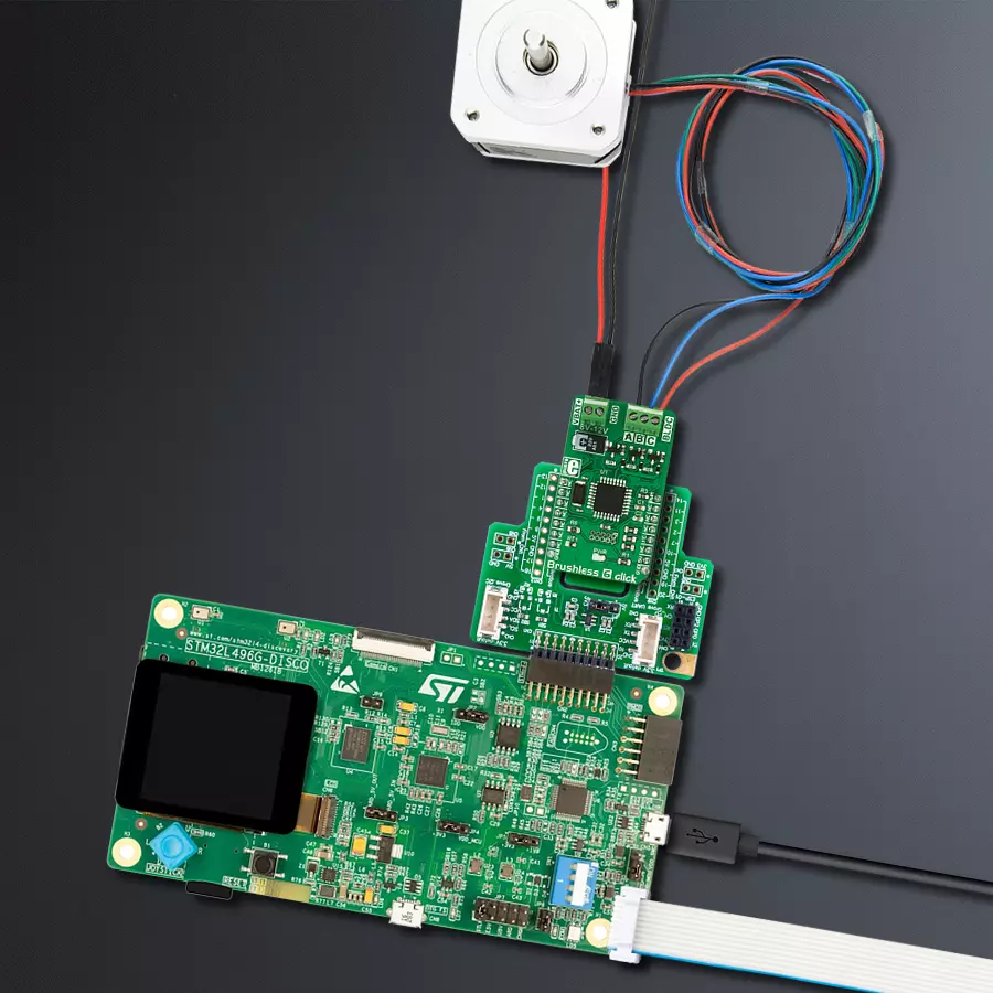
Brushless 6 Click
Dev. board
Discovery kit with STM32L496AG MCU
Compiler
NECTO Studio
MCU
STM32L496AG
Take control of your brushless motors with the most incredible accuracy. Unleash the power of PWM for optimal BLDC management!
A
A
Hardware Overview
How does it work?
Brushless 6 Click is based on the ATmega8A MCU from Microchip. It uses a 50Hz PWM signal at one of the input pins, routed to the PWM pin of the mikroBUS™ socket. The duty cycle of the incoming PWM signal is decoded by the onboard ATmega8A MCU so that a certain pulse width range is used to set the speed and direction of the rotation. The MikroElektronika demo application,
provided with the Brushless 6 Click, uses simplified functions to calibrate and set the speed and direction of the BLDC motor to be used as a reference for future design. Since the MCU output can't be used to drive heavier loads directly, the stator coils are driven through the MOSFET transistors network, controlled by the MCU. The electrical circuit that powers the coils is also
known as the "invertor" circuit because it provides both positive and negative voltages from the connected external power supply. The motor can be connected via the onboard connector, which provides an easy and secure connection. A power connector is also used to connect the external power supply, up to 12V.

Features overview
Development board
The 32L496GDISCOVERY Discovery kit serves as a comprehensive demonstration and development platform for the STM32L496AG microcontroller, featuring an Arm® Cortex®-M4 core. Designed for applications that demand a balance of high performance, advanced graphics, and ultra-low power consumption, this kit enables seamless prototyping for a wide range of embedded solutions. With its innovative energy-efficient
architecture, the STM32L496AG integrates extended RAM and the Chrom-ART Accelerator, enhancing graphics performance while maintaining low power consumption. This makes the kit particularly well-suited for applications involving audio processing, graphical user interfaces, and real-time data acquisition, where energy efficiency is a key requirement. For ease of development, the board includes an onboard ST-LINK/V2-1
debugger/programmer, providing a seamless out-of-the-box experience for loading, debugging, and testing applications without requiring additional hardware. The combination of low power features, enhanced memory capabilities, and built-in debugging tools makes the 32L496GDISCOVERY kit an ideal choice for prototyping advanced embedded systems with state-of-the-art energy efficiency.

Microcontroller Overview
MCU Card / MCU

Architecture
ARM Cortex-M4
MCU Memory (KB)
1024
Silicon Vendor
STMicroelectronics
Pin count
169
RAM (Bytes)
327680
You complete me!
Accessories
Brushless DC (BLDC) Motor with a Hall sensor represents a high-performance motor from the 42BLF motor series. This motor, wired in a star configuration, boasts a Hall Effect angle of 120°, ensuring precise and reliable performance. With a compact motor length of 47mm and a lightweight design tipping the scales at just 0.29kg, this BLDC motor is engineered to meet your needs. Operating flawlessly at a voltage rating of 24VDC and a speed range of 4000 ± 10% RPM, this motor offers consistent and dependable power. It excels in a normal operational temperature range from -20 to +50°C, maintaining efficiency with a rated current of 1.9A. Also, this product seamlessly integrates with all Brushless Click boards™ and those that require BLDC motors with Hall sensors.

Used MCU Pins
mikroBUS™ mapper
Take a closer look
Click board™ Schematic

Step by step
Project assembly

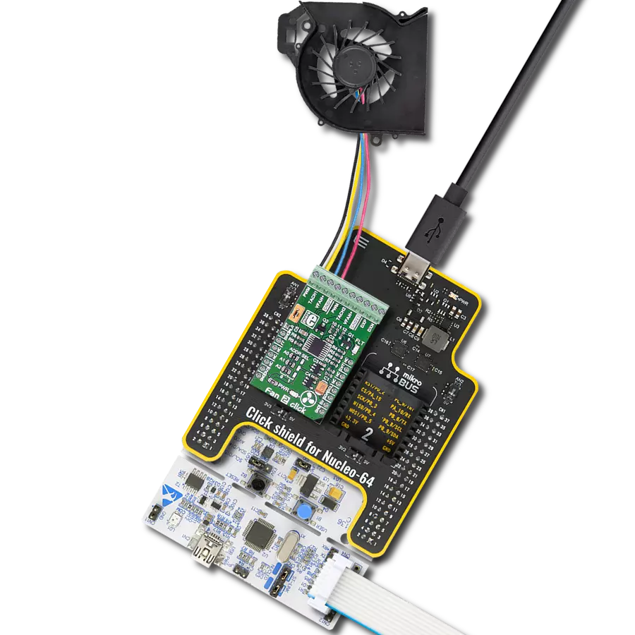
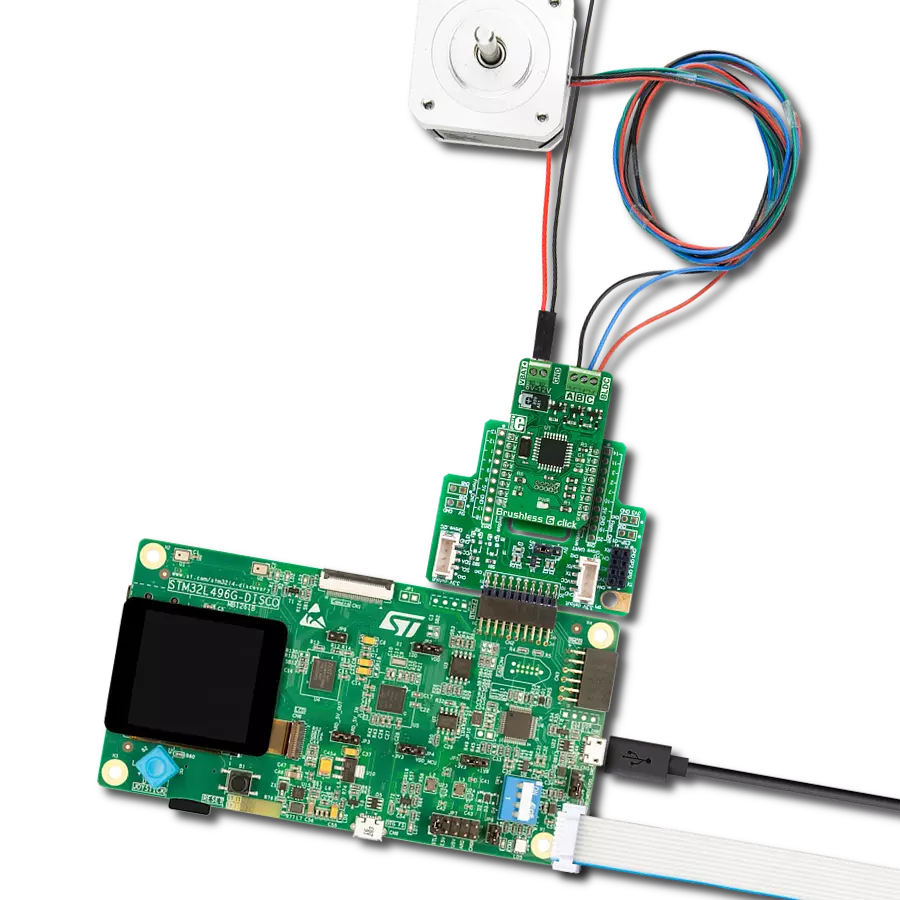
Start by selecting your development board and Click board™. Begin with the Discovery kit with STM32L496AG MCU as your development board.


Track your results in real time
Application Output
1. Application Output - In Debug mode, the 'Application Output' window enables real-time data monitoring, offering direct insight into execution results. Ensure proper data display by configuring the environment correctly using the provided tutorial.

2. UART Terminal - Use the UART Terminal to monitor data transmission via a USB to UART converter, allowing direct communication between the Click board™ and your development system. Configure the baud rate and other serial settings according to your project's requirements to ensure proper functionality. For step-by-step setup instructions, refer to the provided tutorial.

3. Plot Output - The Plot feature offers a powerful way to visualize real-time sensor data, enabling trend analysis, debugging, and comparison of multiple data points. To set it up correctly, follow the provided tutorial, which includes a step-by-step example of using the Plot feature to display Click board™ readings. To use the Plot feature in your code, use the function: plot(*insert_graph_name*, variable_name);. This is a general format, and it is up to the user to replace 'insert_graph_name' with the actual graph name and 'variable_name' with the parameter to be displayed.

Software Support
Library Description
This library contains API for Brushless 6 Click driver.
Key functions:
brushless6_pwm_start- Start PWM modulebrushless6_pwm_stop- Stop PWM modulebrushless6_set_duty_cycle- Generic sets PWM duty cycle
Open Source
Code example
The complete application code and a ready-to-use project are available through the NECTO Studio Package Manager for direct installation in the NECTO Studio. The application code can also be found on the MIKROE GitHub account.
/*!
 * \file
 * \brief Brushless6 Click example
 *
 * # Description
 * Brushless 6 Click is designed to drive a three-phase sensorless.
 *
 * The demo application is composed of two sections :
 *
 * ## Application Init
 * This function initializes and configures the logger and the Click board.
 *
 * ## Application Task
 * This function drives the motor in both directions increasing and decreasing the speed of the motor.
 *
 * ## NOTE
 * The maximal PWM Clock frequency for this Click board is 500 Hz.
 * So, the user will need to decrease the MCU's main clock frequency in MCU Settings in order to get up-to 500 Hz PWM clock frequency.
 *
 *
 * \author MikroE Team
 *
 */
// ------------------------------------------------------------------- INCLUDES

#include "board.h"
#include "log.h"
#include "brushless6.h"

// ------------------------------------------------------------------ VARIABLES

static brushless6_t brushless6;
static log_t logger;

static float duty_cycle;

// ------------------------------------------------------- ADDITIONAL FUNCTIONS

void brushless6_calibration( )
{
    brushless6_pwm_start( &brushless6 );

    brushless6_set_duty_cycle( &brushless6, BRUSHLESS6_MIN_PWM_DC );
    Delay_1sec( );
    Delay_1sec( );
}

void brushless6_setings( )
{
    brushless6_set_duty_cycle( &brushless6, BRUSHLESS6_INIT_DC );
    Delay_1sec( );
    Delay_1sec( );
}

static void clockwise ( )
{
    log_printf( &logger, "\r\n------------------------------\r\n" );
    log_printf( &logger, " * Clockwise *\r\n" );
    Delay_1sec( );

    for( duty_cycle = BRUSHLESS6_INIT_DC; duty_cycle > BRUSHLESS6_1MS_DC; duty_cycle -= BRUSHLESS6_PERIOD )
    {
        brushless6_set_duty_cycle( &brushless6, duty_cycle );
        log_printf( &logger, "  > " );
        Delay_1sec( );
    }

    log_printf( &logger, "\r\n" );

    for( duty_cycle = BRUSHLESS6_1MS_DC; duty_cycle < BRUSHLESS6_INIT_DC; duty_cycle += BRUSHLESS6_PERIOD )
    {
        brushless6_set_duty_cycle( &brushless6, duty_cycle );
        log_printf( &logger, "  < " );
        Delay_1sec( );
    }
}

static void counter_clockwise ( )
{
    log_printf( &logger, "\r\n------------------------------\r\n" );
    log_printf( &logger, " * Counter clockwise *\r\n" );
    Delay_1sec( );

    for( duty_cycle = BRUSHLESS6_INIT_DC; duty_cycle < BRUSHLESS6_2MS_DC - BRUSHLESS6_PERIOD; duty_cycle += BRUSHLESS6_PERIOD )
    {
        brushless6_set_duty_cycle( &brushless6, duty_cycle );
        log_printf( &logger, "  > " );
        Delay_1sec( );
    }
    log_printf( &logger, "\r\n" );

    for( duty_cycle = BRUSHLESS6_2MS_DC - BRUSHLESS6_PERIOD; duty_cycle > BRUSHLESS6_INIT_DC; duty_cycle -= BRUSHLESS6_PERIOD )
    {
        brushless6_set_duty_cycle( &brushless6, duty_cycle );
        log_printf( &logger, "  < " );
        Delay_1sec( );
    }
}

// ------------------------------------------------------ APPLICATION FUNCTIONS

void application_init ( void )
{
    log_cfg_t log_cfg;
    brushless6_cfg_t cfg;

    /**
     * Logger initialization.
     * Default baud rate: 115200
     * Default log level: LOG_LEVEL_DEBUG
     * @note If USB_UART_RX and USB_UART_TX
     * are defined as HAL_PIN_NC, you will
     * need to define them manually for log to work.
     * See @b LOG_MAP_USB_UART macro definition for detailed explanation.
     */
    LOG_MAP_USB_UART( log_cfg );
    log_init( &logger, &log_cfg );
    log_info( &logger, "---- Application Init ----" );

    //  Click initialization.

    brushless6_cfg_setup( &cfg );
    BRUSHLESS6_MAP_MIKROBUS( cfg, MIKROBUS_1 );
    brushless6_init( &brushless6, &cfg );
    brushless6_calibration( );
    brushless6_setings( );
}

void application_task ( void )
{
    clockwise( );
    counter_clockwise( );
}

int main ( void )
{
    /* Do not remove this line or clock might not be set correctly. */
    #ifdef PREINIT_SUPPORTED
    preinit();
    #endif

    application_init( );

    for ( ; ; )
    {
        application_task( );
    }

    return 0;
}


// ------------------------------------------------------------------------ END
Additional Support
Resources
Category:Brushless