Experience the power of customized navigation with BG96 and PIC32MX695F512L
Unleash your inner explorer

Published Aug 30, 2023
Click board™
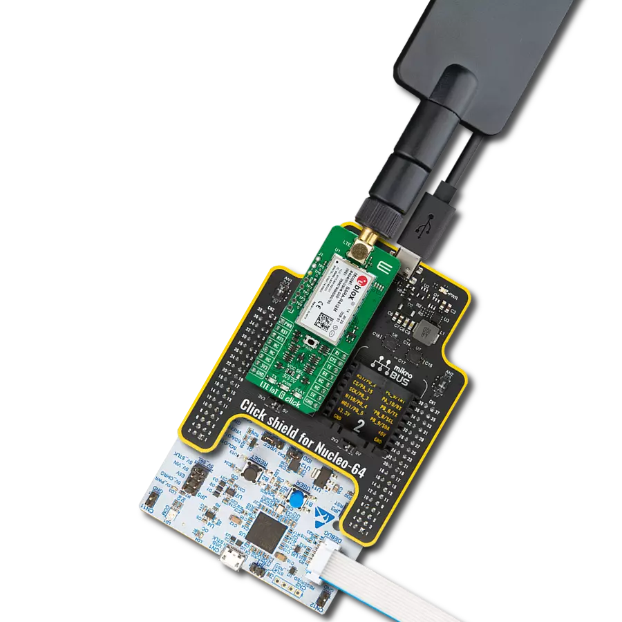
LTE IoT 2 Click
Dev. board
Fusion for PIC32 v8
Compiler
NECTO Studio
MCU
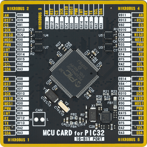
PIC32MX695F512L
Unlock the potential of navigation technology and make a system that is designed to meet your specific goals and aspirations
A
A
Hardware Overview
How does it work?
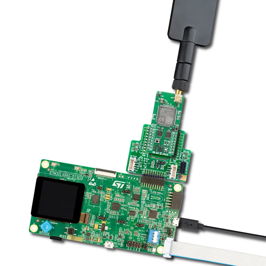
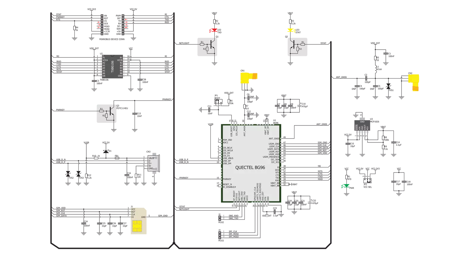
LTE IoT 2 Click is based on the BG96, an LTE module from Quectel, which supports LTE CAT M1 and NB1 technologies, developed with IoT applications in mind. In addition, it supports EGPRS at 850/900/1800/1900 MHz, meaning that it can be used globally; it is not restricted to any region. The support for the CAT M1 and NB1 technologies and the ultra-low power consumption make this module a perfect choice for the forthcoming 3GPP IoT technology. BG96 LTE module is the main component of the click board, and it consists of several internal blocks or sections, such as the RF section, NAND flash, DDR RAM section, the Power Management section, and the cellular baseband processor with the peripheral interfaces. BG96 module supports several peripheral interfaces, including USB, UART, SIM card, I2C, SPI, I2S, and GPIO interfaces. Besides the main UART interface used for exchanging AT commands with the host MCU (UART 1), there are two more auxiliary UART interfaces, one of which is shared with the SPI interface (UART 3/SPI), while the other is used for debugging purposes (UART 2). All the additional UART/SPI interfaces are available on the Click board™ in the form of unpopulated headers, with the pads clearly labeled (RX, TX for the UART debug interface header, and CLK, SDI, and SDO for the SPI interface header). The main UART interface (UART 1) supports baud rates of 9600, 19200, 38400, 57600, 115200, 230400, 460800, 921600, and 3000000 bps, with the default setting to 115200bps. This interface is used for data transmission and exchanging AT communication commands with the host MCU. The debug UART interface (UART 2) operates at 115200bps and is used for firmware debugging and logging the output. The UART 3 interface is multiplexed with the SPI interface and is used to output NEMA and GNSS data sentences. It defaults to UART 3 when the module is used as the modem, but it can also be used as the SPI for the data transfer. These interfaces are not normally used, so the headers come unpopulated. Two standard pitch (2.54) headers can be easily soldered if required. The Quectel BG96 module has to be powered by a clean and stable power supply. The voltage needed for the module to work properly is about 4V, and it is derived from the 5V mikroBUS™ rail
through the MCP1826, a 1A low drop output (LDO) regulator from Microchip. Although the Quectel BG96 module is an ultra-low power device, the cellular network modules, in general, are notorious for their high power consumption while actively exchanging data, so 1A LDO had to be used. The Quectel BG96 module has to be powered by a clean and stable power supply. The voltage needed for the module to work properly is about 4V, and it is derived from the 5V mikroBUS™ rail through the MCP1826, a 1A low drop output (LDO) regulator from Microchip. Although the Quectel BG96 module is an ultra-low power device, the cellular network modules, in general, are notorious for their high power consumption while actively exchanging data, so 1A LDO had to be used. Digital sections of the Quectel BG96 are supplied by 1.8V, so it is necessary to condition the incoming communication bus lines that connect the host MCU with the module. Utilizing its internal LDO regulator, the BG96 module provides the needed reference voltage for one side of the TXB0106, a 6-bit bidirectional level shifter and voltage translator. The reference voltage for the other side of the TXB0106 level shifter is taken from the onboard SMD jumper, labeled as VCC SEL. This jumper selects between 3.3V and 5V from the mikroBUS™, depending on the used MCU type and its logic voltage level requirements. The main UART bus of the Quectel BG96 module is connected to one side of the TXB0106 level shifter, while the other is connected to the respective mikroBUS™ UART pins. However, the Quectel BG96 module is designed as the traditional DCE device (Data Communication Equipment), offering the full serial interface pin count, including the hardware flow control pins (CTS, RTS). These pins are routed to the mikroBUS™ CS (RTS) and the INT pin (CTS) and can be used in the MCU software if hardware flow control is needed. The RI pin is the ringing indicator routed to the mikroBUS™ PWM pin. The STAT pin is used to signal the status of the device. This pin is routed to the mikroBUS™ AN pin through the level shifter and the yellow LED labeled STAT, which is used to indicate the device status visually. The network status is indicated by the red TXD LED located next to the STAT LED. The network status is indicated by the TXD LED. The PWRKEY pin is routed to the mikroBUS™ RST pin.
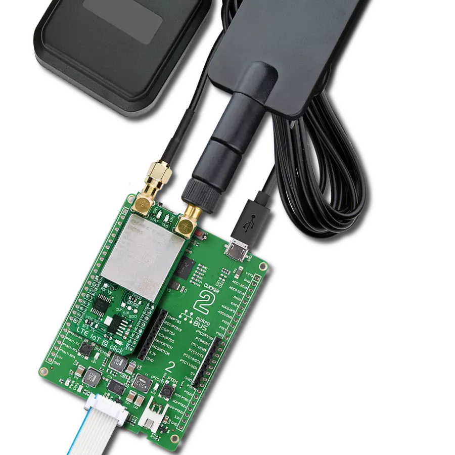
A LOW pulse on this pin for at least 100ms will toggle the device's power status. If powered down and the valid power supply voltage is present, a pulse on this pin will power up the device. The STAT LED, and the STAT (AN) pin will indicate the successful action. If the device is powered up, a pulse on this pin will power the module down. Powering down the module by issuing the AT+QPOWD command is also possible. Both methods are considered safe and will let the module log off from the network and allow the firmware to save important data before completely disconnecting the power supply. An abrupt loss of power might lead to unwanted consequences. LTE IoT 2 click has an SMD jumper labeled as the BOOT, which is used to force the device to boot from the USB, which can be used during the firmware development or for the firmware update. During normal operation, the USB BOOT mode is disabled. This Click board™ is equipped with a micro USB connector. It allows the module to be powered and configured by a personal computer. Quectel Wireless Solutions Company offers a software suite and drivers for all major OSes, offering connectivity for various configurations. The Micro SIM card holder on the back of the Click board™ is used to install a micro SIM card. This device cannot be used without a valid SIM card, which allows connection to the cellular network. Both 1.8V and 3V SIM card types are supported. Two SMA antenna connectors are used to connect the appropriate antennas: a main antenna SMA connector and a secondary (GNSS) antenna SMA connector. The main antenna connects the module to the LTE base station. LTE IoT 2 click can be used with a GSM/GPRS antenna, such as the Rubber GSM/GPRS Antenna right angle, found in our shop. The secondary, global positioning (GNSS) antenna can be of both active or passive type since the connector offers power supply from the internal LDO of the BG96 (1.8V). The module supports several global positioning technologies, including GPS, GLONASS, BeiDou/Compass, Galileo and QZSS. The Click board™ can use the Active GPS antenna for global positioning purposes, which can be found at our shop. The GNSS interface is turned off by default and should be enabled by an AT command if required.

Features overview
Development board
Fusion for PIC32 v8 is a development board specially designed for the needs of rapid development of embedded applications. It supports a wide range of Microchip's PIC32 microcontrollers regardless of their number of pins and a broad set of unique functions, such as the first-ever embedded debugger/programmer over WiFi. The development board is well organized and designed so that the end-user has all the necessary elements, such as switches, buttons, indicators, connectors, and others, in one place. Thanks to innovative manufacturing technology, Fusion for PIC32 v8 provides a fluid and immersive working experience, allowing access anywhere and under any circumstances at any time. Each part of the
Fusion for PIC32 v8 development board contains the components necessary for the most efficient operation of the same board. In addition to the advanced integrated CODEGRIP programmer/debugger module, which offers many valuable programming/debugging options and seamless integration with the Mikroe software environment, the board also includes a clean and regulated power supply module for the development board. It can use a wide range of external power sources, including a battery, an external 12V power supply, and a power source via the USB Type-C (USB-C) connector. Communication options such as USB-UART, USB HOST/DEVICE, CAN (on the MCU card, if
supported), and Ethernet is also included. In addition, it also has the well-established mikroBUS™ standard, a standardized socket for the MCU card (SiBRAIN standard), and two display options for the TFT board line of products and character-based LCD. Fusion for PIC32 v8 is an integral part of the Mikroe ecosystem for rapid development. Natively supported by Mikroe software tools, it covers many aspects of prototyping and development thanks to a considerable number of different Click boards™ (over a thousand boards), the number of which is growing every day.

Microcontroller Overview
MCU Card / MCU
Type
8th Generation
Architecture
PIC32
MCU Memory (KB)
512
Silicon Vendor
Microchip
Pin count
100
RAM (Bytes)
131072
You complete me!
Accessories
LTE Flat Rotation Antenna is a versatile choice for boosting the performance of 3G/4G LTE devices. With a wide frequency range of 700-2700MHz, it ensures optimal connectivity on major cellular bands worldwide. This flat antenna features an SMA male connector, making it easy to attach directly to your device or SMA module connector. One of its standout features is its adjustable angle, which can be set in 45⁰ increments (0⁰/45⁰/90⁰), allowing you to fine-tune the antenna's orientation for maximum signal reception. With an impedance of 50Ω and a VSW Ratio of <2.0:1, this antenna ensures a reliable and efficient connection. Its 5dB gain, vertical polarization, and omnidirectional radiation pattern enhance signal strength, making it suitable for various applications. Measuring 196mm in length and 38mm in width, this antenna offers a compact yet effective solution for improving your connectivity. With a maximum input power of 50W, it can handle the demands of various devices.

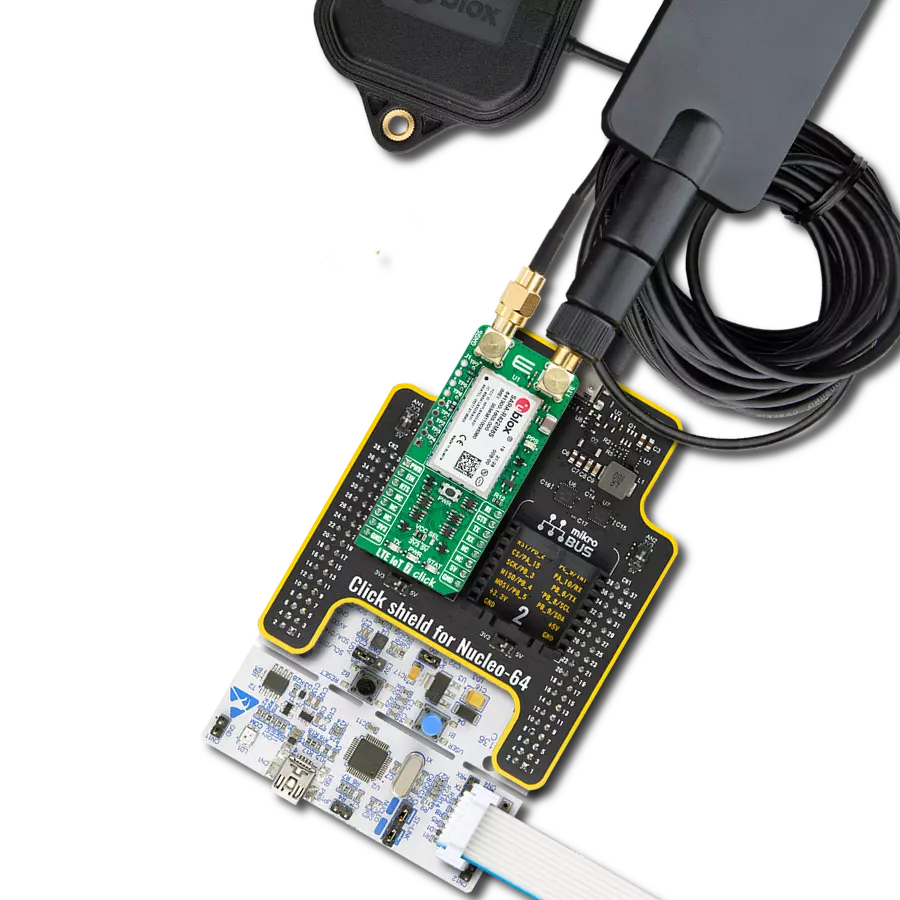
GNSS L1/L5 Active External Antenna (YB0017AA) is an active patch antenna from Quectel that supports GNSS L1/L5 BD B1/B2 GLONASS L1, offering excellent performance with its high gain and efficiency for fleet management, navigation, RTK, and many other tracking applications. The magnetic-mounting antenna, with dimensions of 61.5×56.5×23mm, is designed to work with various ground plane sizes or in free space and is connected to the device by a 3m cable with an SMA male connector.

Used MCU Pins
mikroBUS™ mapper
Take a closer look
Click board™ Schematic
Step by step
Project assembly

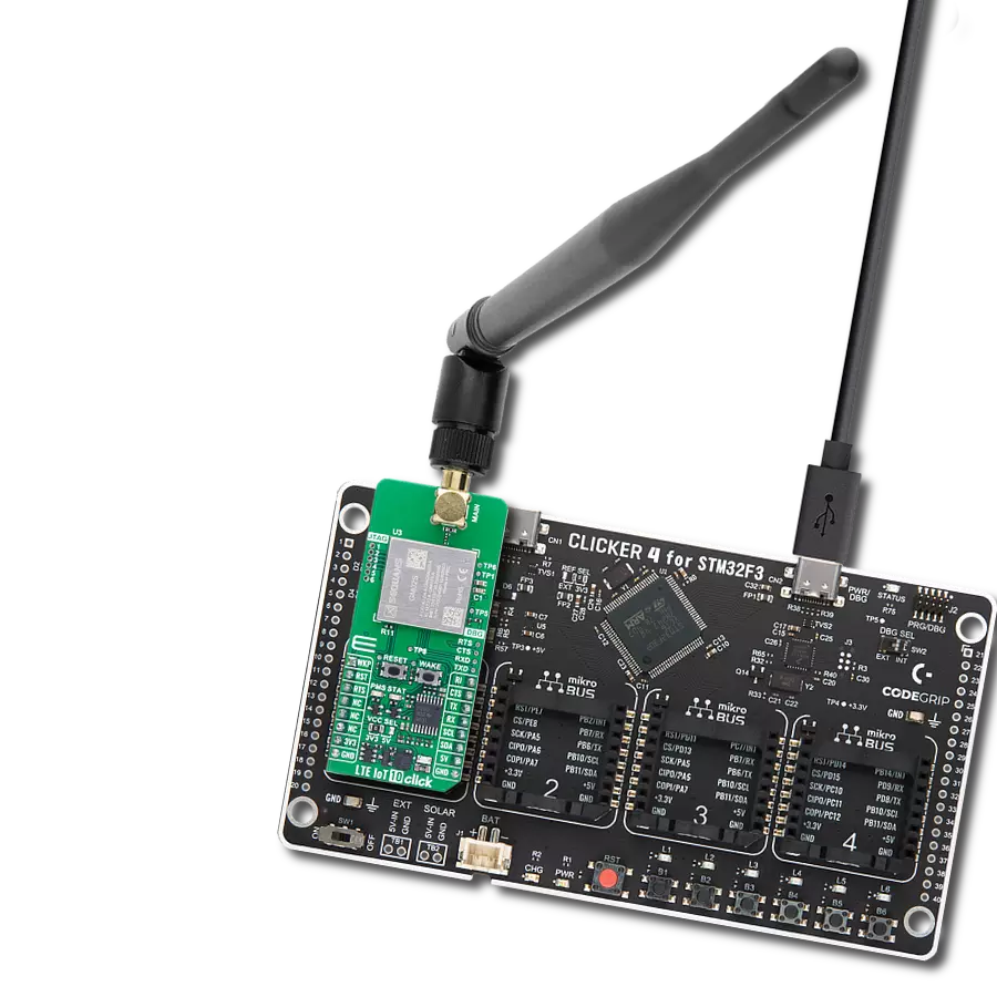
Start by selecting your development board and Click board™. Begin with the Fusion for PIC32 v8 as your development board.


Software Support
Library Description
This library contains API for LTE IoT 2 Click driver.
Key functions:
lteiot2_send_cmd_with_parameter- Send command function with parameterlteiot2_send_sms_pdu- LTE IoT 2 send SMS in PDU modelteiot2_generic_parser- Generic parser function.
Open Source
Code example
The complete application code and a ready-to-use project are available through the NECTO Studio Package Manager for direct installation in the NECTO Studio. The application code can also be found on the MIKROE GitHub account.
/*!
* \file
* \brief LteIot2 Click example
*
* # Description
* This example reads and processes data from LTE IoT 2 Click.
*
* The demo application is composed of two sections :
*
* ## Application Init
* Initializes the driver and powers up the module, then sets default configuration
* for connecting the device to network.
*
* ## Application Task
* Waits for the device to connect to network, then waits for the GPS position fix. Once it get a fix,
* it sends an SMS with GPS info to the selected phone number approximately every 40 seconds.
*
* ## Additional Function
* - static void lteiot2_clear_app_buf ( void )
* - static void lteiot2_error_check( err_t error_flag )
* - static void lteiot2_log_app_buf ( void )
* - static void lteiot2_check_connection( void )
* - static err_t lteiot2_rsp_check ( void )
* - static err_t lteiot2_process ( void )
* - static void gps_parser_application ( void )
*
* @note
* In order for the example to work, user needs to set the phone number to which he wants
* to send an SMS, and also will need to set an APN and SMSC (required for PDU mode only) of entered SIM card.
* Enter valid data for the following macros: SIM_APN, SIM_SMSC and PHONE_NUMBER_TO_MESSAGE.
* E.g.
SIM_APN "vipmobile"
SIM_SMSC "+381610401"
PHONE_NUMBER_TO_MESSAGE "+381659999999"
*
* @author MikroE Team
*
*/
// ------------------------------------------------------------------- INCLUDES
#include "board.h"
#include "log.h"
#include "lteiot2.h"
#include "string.h"
#define APP_OK 0
#define APP_ERROR_DRIVER -1
#define APP_ERROR_OVERFLOW -2
#define APP_ERROR_TIMEOUT -3
#define RSP_OK "OK"
#define RSP_ERROR "ERROR"
#define SIM_APN "" // Set valid SIM APN
#define SIM_SMSC "" // Set valid SMS Service Center Address - only in PDU mode
#define PHONE_NUMBER_TO_MESSAGE "" // Set Phone number to message
#define PROCESS_BUFFER_SIZE 280
#define WAIT_FOR_CONNECTION 0
#define CONNECTED_TO_NETWORK 1
static lteiot2_t lteiot2;
static log_t logger;
static char app_buf[ PROCESS_BUFFER_SIZE ] = { 0 };
static int32_t app_buf_len = 0;
static int32_t app_buf_cnt = 0;
static uint8_t app_connection_status = WAIT_FOR_CONNECTION;
static err_t app_error_flag;
static uint8_t gps_parser_flag = 0;
static uint8_t gps_info_message[ 200 ] = { 0 };
/**
* @brief LTE IoT 2 clearing application buffer.
* @details This function clears memory of application buffer and reset its length and counter.
* @note None.
*/
static void lteiot2_clear_app_buf ( void );
/**
* @brief LTE IoT 2 data reading function.
* @details This function reads data from device and concats data to application buffer.
*
* @return @li @c 0 - Read some data.
* @li @c -1 - Nothing is read.
* @li @c -2 - Application buffer overflow.
*
* See #err_t definition for detailed explanation.
* @note None.
*/
static err_t lteiot2_process ( void );
/**
* @brief LTE IoT 2 check for errors.
* @details This function checks for different types of errors and logs them on UART.
* @note None.
*/
static void lteiot2_error_check( err_t error_flag );
/**
* @brief LTE IoT 2 logs application buffer.
* @details This function logs data from application buffer.
* @note None.
*/
static void lteiot2_log_app_buf ( void );
/**
* @brief LTE IoT 2 response check.
* @details This function checks for response and returns the status of response.
*
* @return application status.
* See #err_t definition for detailed explanation.
* @note None.
*/
static err_t lteiot2_rsp_check ( void );
/**
* @brief LTE IoT 2 check connection.
* @details This function checks connection to the network and
* logs that status to UART.
*
* @note None.
*/
static void lteiot2_check_connection( void );
/**
* @brief GPS parser application.
* @param rsp Response buffer.
* @details This function logs GPS data on the USB UART and stores data in gps_info_message buffer.
*
* @note None.
*/
static void gps_parser_application ( char *rsp );
// ------------------------------------------------------ APPLICATION FUNCTIONS
void application_init ( void )
{
log_cfg_t log_cfg;
lteiot2_cfg_t cfg;
/**
* Logger initialization.
* Default baud rate: 115200
* Default log level: LOG_LEVEL_DEBUG
* @note If USB_UART_RX and USB_UART_TX
* are defined as HAL_PIN_NC, you will
* need to define them manually for log to work.
* See @b LOG_MAP_USB_UART macro definition for detailed explanation.
*/
LOG_MAP_USB_UART( log_cfg );
log_init( &logger, &log_cfg );
log_info( &logger, "---- Application Init ----" );
// Click initialization.
lteiot2_cfg_setup( &cfg );
LTEIOT2_MAP_MIKROBUS( cfg, MIKROBUS_1 );
lteiot2_init( <eiot2, &cfg );
lteiot2_module_power( <eiot2, LTEIOT2_MODULE_POWER_ON );
// dummy read
lteiot2_process( );
lteiot2_clear_app_buf( );
// AT
lteiot2_send_cmd( <eiot2, LTEIOT2_CMD_AT );
app_error_flag = lteiot2_rsp_check( );
lteiot2_error_check( app_error_flag );
Delay_ms ( 500 );
// ATI - product information
lteiot2_send_cmd( <eiot2, LTEIOT2_CMD_ATI );
app_error_flag = lteiot2_rsp_check( );
lteiot2_error_check( app_error_flag );
Delay_ms ( 500 );
// CGMR - firmware version
lteiot2_send_cmd( <eiot2, LTEIOT2_CMD_CGMR );
app_error_flag = lteiot2_rsp_check( );
lteiot2_error_check( app_error_flag );
Delay_ms ( 500 );
// COPS - deregister from network
lteiot2_send_cmd_with_parameter( <eiot2, LTEIOT2_CMD_COPS, "2" );
app_error_flag = lteiot2_rsp_check( );
lteiot2_error_check( app_error_flag );
Delay_ms ( 500 );
// CGDCONT - set sim apn
lteiot2_set_sim_apn( <eiot2, SIM_APN );
app_error_flag = lteiot2_rsp_check( );
lteiot2_error_check( app_error_flag );
Delay_ms ( 500 );
// CFUN - full funtionality
lteiot2_send_cmd_with_parameter( <eiot2, LTEIOT2_CMD_CFUN, "1" );
app_error_flag = lteiot2_rsp_check( );
lteiot2_error_check( app_error_flag );
Delay_ms ( 500 );
// COPS - automatic mode
lteiot2_send_cmd_with_parameter( <eiot2, LTEIOT2_CMD_COPS, "0" );
app_error_flag = lteiot2_rsp_check( );
lteiot2_error_check( app_error_flag );
Delay_ms ( 1000 );
Delay_ms ( 1000 );
// CREG - network registration status
lteiot2_send_cmd_with_parameter( <eiot2, LTEIOT2_CMD_CREG, "2" );
app_error_flag = lteiot2_rsp_check( );
lteiot2_error_check( app_error_flag );
Delay_ms ( 500 );
// CIMI - request IMSI
lteiot2_send_cmd( <eiot2, LTEIOT2_CMD_CIMI );
app_error_flag = lteiot2_rsp_check( );
lteiot2_error_check( app_error_flag );
Delay_ms ( 500 );
// QGPSCFG - Set <nmeasrc> to 1 to enable acquisition of NMEA sentences via AT+QGPSGNMEA
lteiot2_send_cmd_with_parameter( <eiot2, LTEIOT2_CMD_QGPSCFG, "\"nmeasrc\",1" );
app_error_flag = lteiot2_rsp_check( );
lteiot2_error_check( app_error_flag );
Delay_ms ( 500 );
// QGPS - Set to 1 to turn ON GNSS
lteiot2_send_cmd_with_parameter( <eiot2, LTEIOT2_CMD_QGPS, "1" );
app_error_flag = lteiot2_rsp_check( );
lteiot2_error_check( app_error_flag );
Delay_ms ( 500 );
app_buf_len = 0;
app_buf_cnt = 0;
app_connection_status = WAIT_FOR_CONNECTION;
log_info( &logger, " Application Task " );
Delay_ms ( 1000 );
Delay_ms ( 1000 );
Delay_ms ( 1000 );
Delay_ms ( 1000 );
Delay_ms ( 1000 );
}
void application_task ( void )
{
if ( app_connection_status == WAIT_FOR_CONNECTION )
{
// CGATT - request IMSI
lteiot2_send_cmd_check( <eiot2, LTEIOT2_CMD_CGATT );
app_error_flag = lteiot2_rsp_check( );
lteiot2_error_check( app_error_flag );
Delay_ms ( 500 );
// CREG - network registration status
lteiot2_send_cmd_check( <eiot2, LTEIOT2_CMD_CREG );
app_error_flag = lteiot2_rsp_check( );
lteiot2_error_check( app_error_flag );
Delay_ms ( 500 );
// CSQ - signal quality
lteiot2_send_cmd( <eiot2, LTEIOT2_CMD_CSQ );
app_error_flag = lteiot2_rsp_check( );
lteiot2_error_check( app_error_flag );
Delay_ms ( 1000 );
Delay_ms ( 1000 );
Delay_ms ( 1000 );
Delay_ms ( 1000 );
Delay_ms ( 1000 );
}
else
{
log_info( &logger, "CONNECTED TO NETWORK" );
// SMS message format - PDU mode
lteiot2_send_cmd_with_parameter( <eiot2, LTEIOT2_CMD_CMGF, "0" );
app_error_flag = lteiot2_rsp_check( );
lteiot2_error_check( app_error_flag );
Delay_ms ( 1000 );
Delay_ms ( 1000 );
Delay_ms ( 1000 );
for( ; ; )
{
// Get GPS info
gps_parser_flag = 1;
lteiot2_send_cmd_with_parameter( <eiot2, LTEIOT2_CMD_QGPSGNMEA, "\"GGA\"" );
app_error_flag = lteiot2_rsp_check( );
lteiot2_error_check( app_error_flag );
Delay_ms ( 1000 );
Delay_ms ( 1000 );
Delay_ms ( 1000 );
if ( gps_parser_flag == 0 )
{
log_printf( &logger, "> Sending message to phone number...\r\n" );
lteiot2_send_sms_pdu ( <eiot2, SIM_SMSC, PHONE_NUMBER_TO_MESSAGE, gps_info_message );
app_error_flag = lteiot2_rsp_check( );
lteiot2_error_check( app_error_flag );
// 30 seconds delay
Delay_ms ( 1000 );
Delay_ms ( 1000 );
Delay_ms ( 1000 );
Delay_ms ( 1000 );
Delay_ms ( 1000 );
Delay_ms ( 1000 );
Delay_ms ( 1000 );
Delay_ms ( 1000 );
Delay_ms ( 1000 );
Delay_ms ( 1000 );
Delay_ms ( 1000 );
Delay_ms ( 1000 );
Delay_ms ( 1000 );
Delay_ms ( 1000 );
Delay_ms ( 1000 );
Delay_ms ( 1000 );
Delay_ms ( 1000 );
Delay_ms ( 1000 );
Delay_ms ( 1000 );
Delay_ms ( 1000 );
Delay_ms ( 1000 );
Delay_ms ( 1000 );
Delay_ms ( 1000 );
Delay_ms ( 1000 );
Delay_ms ( 1000 );
Delay_ms ( 1000 );
Delay_ms ( 1000 );
Delay_ms ( 1000 );
Delay_ms ( 1000 );
Delay_ms ( 1000 );
}
}
}
}
int main ( void )
{
/* Do not remove this line or clock might not be set correctly. */
#ifdef PREINIT_SUPPORTED
preinit();
#endif
application_init( );
for ( ; ; )
{
application_task( );
}
return 0;
}
static void lteiot2_clear_app_buf ( void )
{
memset( app_buf, 0, app_buf_len );
app_buf_len = 0;
app_buf_cnt = 0;
}
static err_t lteiot2_process ( void )
{
err_t return_flag = APP_ERROR_DRIVER;
int32_t rx_size;
char rx_buff[ PROCESS_BUFFER_SIZE ] = { 0 };
rx_size = lteiot2_generic_read( <eiot2, rx_buff, PROCESS_BUFFER_SIZE );
if ( rx_size > 0 )
{
int32_t buf_cnt = 0;
return_flag = APP_OK;
if ( app_buf_len + rx_size >= PROCESS_BUFFER_SIZE )
{
lteiot2_clear_app_buf( );
return_flag = APP_ERROR_OVERFLOW;
}
else
{
buf_cnt = app_buf_len;
app_buf_len += rx_size;
}
for ( int32_t rx_cnt = 0; rx_cnt < rx_size; rx_cnt++ )
{
if ( rx_buff[ rx_cnt ] != 0 )
{
app_buf[ ( buf_cnt + rx_cnt ) ] = rx_buff[ rx_cnt ];
}
else
{
app_buf_len--;
buf_cnt--;
}
}
}
return return_flag;
}
static err_t lteiot2_rsp_check ( void )
{
uint16_t timeout_cnt = 0;
uint16_t timeout = 10000;
err_t error_flag = lteiot2_process( );
if ( ( error_flag != 0 ) && ( error_flag != -1 ) )
{
return error_flag;
}
while ( ( strstr( app_buf, RSP_OK ) == 0 ) && ( strstr( app_buf, RSP_ERROR ) == 0 ) )
{
error_flag = lteiot2_process( );
if ( ( error_flag != 0 ) && ( error_flag != -1 ) )
{
return error_flag;
}
timeout_cnt++;
if ( timeout_cnt > timeout )
{
while ( ( strstr( app_buf, RSP_OK ) == 0 ) && ( strstr( app_buf, RSP_ERROR ) == 0 ) )
{
lteiot2_send_cmd( <eiot2, LTEIOT2_CMD_AT );
lteiot2_process( );
Delay_ms ( 100 );
}
lteiot2_clear_app_buf( );
return APP_ERROR_TIMEOUT;
}
Delay_ms ( 1 );
}
lteiot2_check_connection();
lteiot2_log_app_buf();
return APP_OK;
}
static void lteiot2_error_check( err_t error_flag )
{
if ( ( error_flag != 0 ) && ( error_flag != -1 ) )
{
switch ( error_flag )
{
case -2:
log_error( &logger, " Overflow!" );
break;
case -3:
log_error( &logger, " Timeout!" );
break;
default:
break;
}
}
}
static void lteiot2_log_app_buf ( void )
{
if ( gps_parser_flag == 1 )
{
gps_parser_application( app_buf );
}
else
{
for ( int32_t buf_cnt = 0; buf_cnt < app_buf_len; buf_cnt++ )
{
log_printf( &logger, "%c", app_buf[ buf_cnt ] );
}
log_printf( &logger, "\r\n-----------------------------------\r\n" );
}
lteiot2_clear_app_buf( );
}
static void lteiot2_check_connection( void )
{
#define CONNECTED "+CGATT: 1"
if ( strstr( app_buf, CONNECTED ) != 0 )
{
app_connection_status = CONNECTED_TO_NETWORK;
}
}
static void gps_parser_application ( char *rsp )
{
char element_buf[ 200 ] = { 0 };
memset( gps_info_message, 0, 200 );
lteiot2_generic_parser( rsp, LTEIOT2_NMEA_GPGGA, LTEIOT2_GPGGA_LATITUDE, element_buf );
if ( strlen( element_buf ) > 0 )
{
strcpy( gps_info_message, "LTE IoT 2 Click - GPS info\n" );
strcat( gps_info_message, "Latitude: " );
strncat( gps_info_message, element_buf, 2 );
strcat( gps_info_message, " deg, " );
strcat( gps_info_message, &element_buf[ 2 ] );
strcat( gps_info_message, "'" );
log_printf( &logger, "Latitude: %.2s deg, %s'\r\n", element_buf, &element_buf[ 2 ] );
lteiot2_generic_parser( rsp, LTEIOT2_NMEA_GPGGA, LTEIOT2_GPGGA_LONGITUDE, element_buf );
strcat( gps_info_message, "\nLongitude: " );
strncat( gps_info_message, element_buf, 3 );
strcat( gps_info_message, " deg, " );
strcat( gps_info_message, &element_buf[ 3 ] );
strcat( gps_info_message, "'" );
log_printf( &logger, "Longitude: %.3s deg, %s'\r\n", element_buf, &element_buf[ 3 ] );
memset( element_buf, 0, sizeof( element_buf ) );
lteiot2_generic_parser( rsp, LTEIOT2_NMEA_GPGGA, LTEIOT2_GPGGA_ALTITUDE, element_buf );
strcat( gps_info_message, "\nAltitude: " );
strcat( gps_info_message, element_buf );
strcat( gps_info_message, " m" );
log_printf( &logger, "Altitude: %s m\r\n", element_buf );
gps_parser_flag = 0;
}
else
{
log_printf( &logger, "Waiting for the position fix..." );
}
log_printf( &logger, "\r\n-----------------------------------\r\n" );
}
// ------------------------------------------------------------------------ END