Create a secure and distinctive digital identity using DS2401 and STM32L496AG
Your ID, your signature!
Published Jul 22, 2025
Click board™
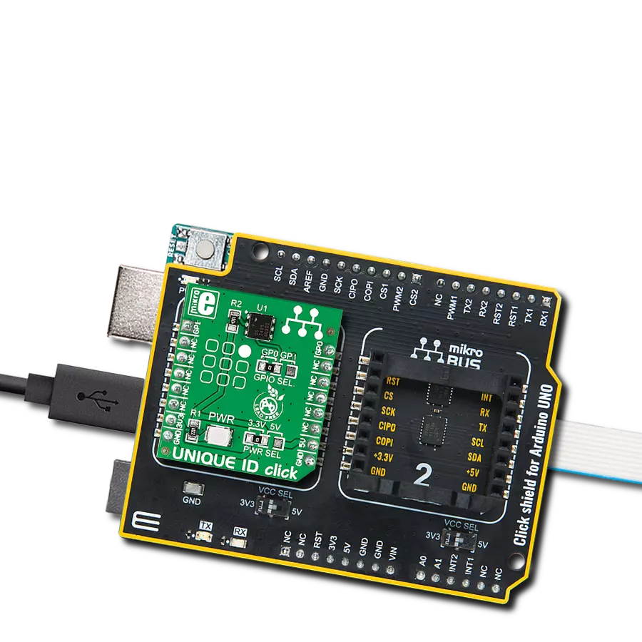
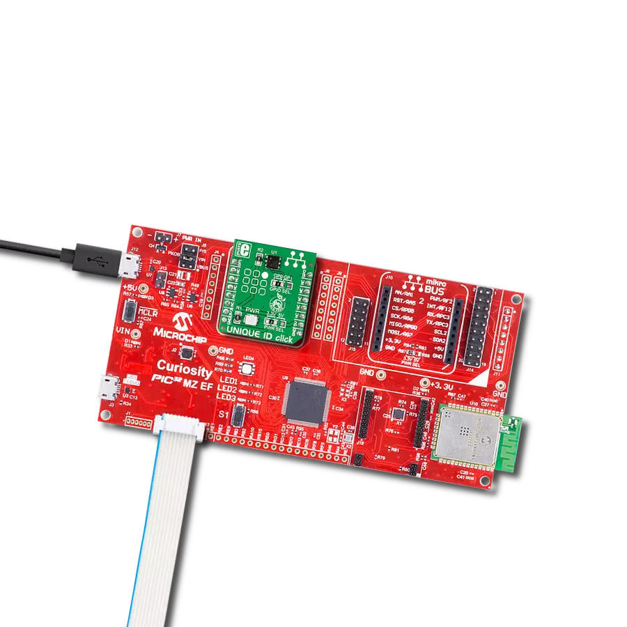
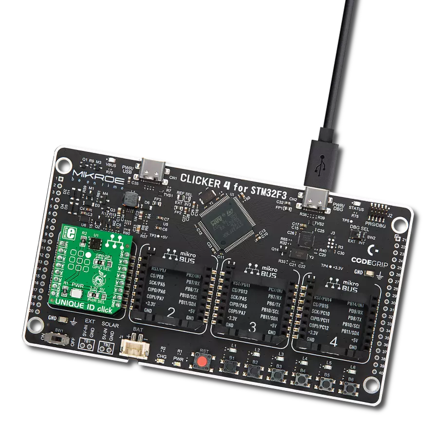
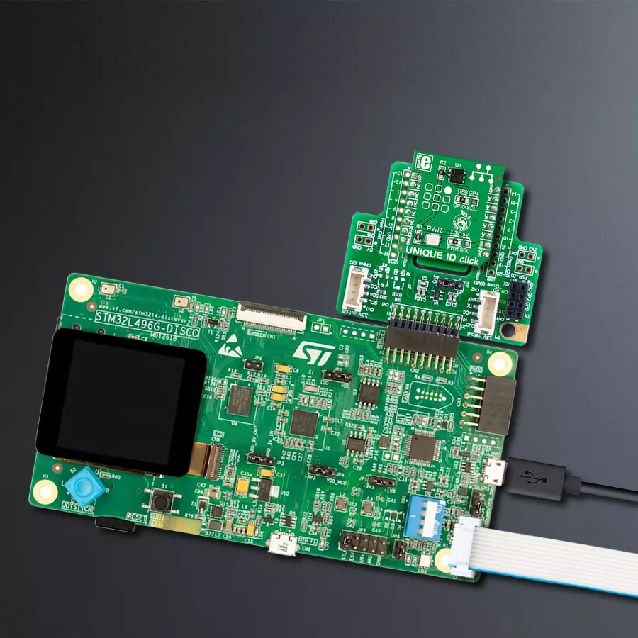
UNIQUE ID Click
Dev. board
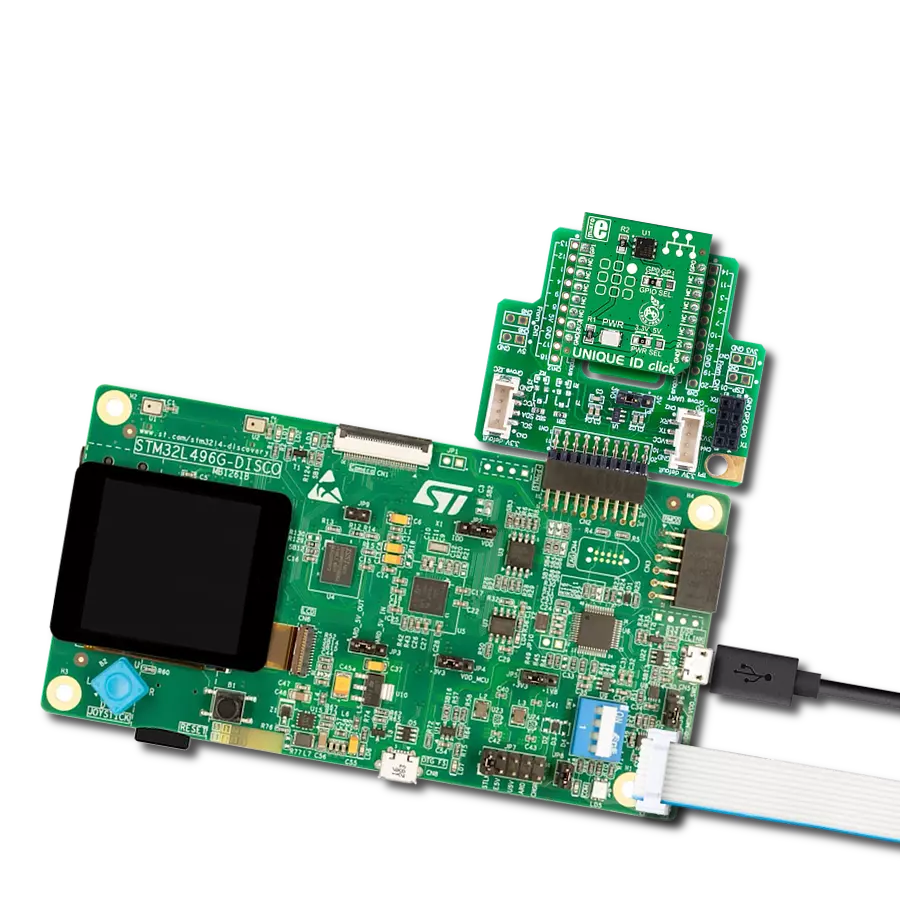
Discovery kit with STM32L496AG MCU
Compiler
NECTO Studio
MCU
STM32L496AG
Unlock a world of possibilities with your personalized digital ID!
A
A
Hardware Overview
How does it work?
Unique ID Click is based on the DS2401, a guaranteed unique 64-bit ROM ID chip from Analog Devices. The 64-bit ROM includes a unique 48-bit serial number, an 8-bit CRC, and an 8-bit Family Code (01h). Its internal ROM is accessed via a single data line with a communication speed of up to 16.3Kbps. In perspective, multiple DS2401 devices can reside on a common 1-Wire net, with a built-in multidrop controller that ensures compatibility with other 1-Wire devices. The
DS2401 features presence pulse acknowledgment when the reader first applies a voltage, where the power for reading and writing the device is derived from the data line itself. The Unique ID Click uses a 1-Wire bus interface to communicate to the host MCU through one of the GPIOs (GP0, GP1) of the mikroBUS™ socket, selectable by the onboard GPIO SEL jumper. This protocol defines bus transactions regarding the bus state during specified time slots initiated on the falling edge of
sync pulses from the host bus. All data is read and written the least significant bit first. This Click board™ can operate with either 3.3V or 5V logic voltage levels selected via the PWR SEL jumper. This way, both 3.3V and 5V capable MCUs can use the communication lines properly. However, the Click board™ comes equipped with a library containing easy-to-use functions and an example code that can be used, as a reference, for further development.

Features overview
Development board
The 32L496GDISCOVERY Discovery kit serves as a comprehensive demonstration and development platform for the STM32L496AG microcontroller, featuring an Arm® Cortex®-M4 core. Designed for applications that demand a balance of high performance, advanced graphics, and ultra-low power consumption, this kit enables seamless prototyping for a wide range of embedded solutions. With its innovative energy-efficient
architecture, the STM32L496AG integrates extended RAM and the Chrom-ART Accelerator, enhancing graphics performance while maintaining low power consumption. This makes the kit particularly well-suited for applications involving audio processing, graphical user interfaces, and real-time data acquisition, where energy efficiency is a key requirement. For ease of development, the board includes an onboard ST-LINK/V2-1
debugger/programmer, providing a seamless out-of-the-box experience for loading, debugging, and testing applications without requiring additional hardware. The combination of low power features, enhanced memory capabilities, and built-in debugging tools makes the 32L496GDISCOVERY kit an ideal choice for prototyping advanced embedded systems with state-of-the-art energy efficiency.

Microcontroller Overview
MCU Card / MCU

Architecture
ARM Cortex-M4
MCU Memory (KB)
1024
Silicon Vendor
STMicroelectronics
Pin count
169
RAM (Bytes)
327680
Used MCU Pins
mikroBUS™ mapper
Take a closer look
Click board™ Schematic

Step by step
Project assembly

Start by selecting your development board and Click board™. Begin with the Discovery kit with STM32L496AG MCU as your development board.


Track your results in real time
Application Output
1. Application Output - In Debug mode, the 'Application Output' window enables real-time data monitoring, offering direct insight into execution results. Ensure proper data display by configuring the environment correctly using the provided tutorial.

2. UART Terminal - Use the UART Terminal to monitor data transmission via a USB to UART converter, allowing direct communication between the Click board™ and your development system. Configure the baud rate and other serial settings according to your project's requirements to ensure proper functionality. For step-by-step setup instructions, refer to the provided tutorial.

3. Plot Output - The Plot feature offers a powerful way to visualize real-time sensor data, enabling trend analysis, debugging, and comparison of multiple data points. To set it up correctly, follow the provided tutorial, which includes a step-by-step example of using the Plot feature to display Click board™ readings. To use the Plot feature in your code, use the function: plot(*insert_graph_name*, variable_name);. This is a general format, and it is up to the user to replace 'insert_graph_name' with the actual graph name and 'variable_name' with the parameter to be displayed.

Software Support
Library Description
This library contains API for Unique ID Click driver.
Key functions:
uniqueid_read_id- This function reads Family Code and Serial Number of device's ROM memory
Open Source
Code example
The complete application code and a ready-to-use project are available through the NECTO Studio Package Manager for direct installation in the NECTO Studio. The application code can also be found on the MIKROE GitHub account.
/*!
 * @file main.c
 * @brief UNIQUE ID Click example.
 *
 * # Description
 * This example demonstrates the use of UNIQUE ID Click board by reading and
 * displaying Family Code and Serial Number on the UART Terminal.
 *
 * The demo application is composed of two sections :
 *
 * ## Application Init
 * Initializes both logger config object and
 * Click config object.
 *
 * ## Application Task
 * Demonstrates the usage of uniqueid_read_id function,
 * which stores the Family Code and Serial Number of the Click in
 * family_code and serial_num variables. Both values will be displayed
 * on the UART Terminal.
 *
 * @author Aleksandra Cvjeticanin
 *
 */

#include "board.h"
#include "log.h"
#include "uniqueid.h"

static uniqueid_t uniqueid;
static log_t logger;


void application_init ( void )
{
    log_cfg_t log_cfg;  /**< Logger config object. */
    uniqueid_cfg_t uniqueid_cfg;  /**< Click config object. */

    /**
     * Logger initialization.
     * Default baud rate: 115200
     * Default log level: LOG_LEVEL_DEBUG
     * @note If USB_UART_RX and USB_UART_TX
     * are defined as HAL_PIN_NC, you will
     * need to define them manually for log to work.
     * See @b LOG_MAP_USB_UART macro definition for detailed explanation.
     */
    LOG_MAP_USB_UART( log_cfg );
    log_init( &logger, &log_cfg );
    log_info( &logger, " Application Init " );

    // Click initialization
    uniqueid_cfg_setup( &uniqueid_cfg );
    UNIQUEID_MAP_MIKROBUS( uniqueid_cfg, MIKROBUS_1 );
    if ( ONE_WIRE_ERROR == uniqueid_init( &uniqueid, &uniqueid_cfg ) )
    {
        log_error( &logger, " Initialization error." );
        for ( ; ; );
    }

    log_info( &logger, " Application Task " );
}

void application_task ( void )
{
    uint8_t family_code;
    uint8_t serial_num[ 6 ];

    if ( UNIQUEID_OK == uniqueid_read_id( &uniqueid, &family_code, &serial_num[ 0 ] ) )
    {
        log_printf( &logger, "Family Code = 0x%.2X\r\n", ( uint16_t ) family_code );
        log_printf( &logger, "Serial Number = 0x%.2X%.2X%.2X%.2X%.2X%.2X\r\n",
                    ( uint16_t ) serial_num[ 0 ], ( uint16_t ) serial_num[ 1 ],
                    ( uint16_t ) serial_num[ 2 ], ( uint16_t ) serial_num[ 3 ],
                    ( uint16_t ) serial_num[ 4 ], ( uint16_t ) serial_num[ 5 ] );
    }

    Delay_ms ( 1000 );
}

int main ( void )
{
    /* Do not remove this line or clock might not be set correctly. */
    #ifdef PREINIT_SUPPORTED
    preinit();
    #endif

    application_init( );

    for ( ; ; )
    {
        application_task( );
    }

    return 0;
}

// ------------------------------------------------------------------------ END
Additional Support
Resources
Category:ID