Bridge the gap between I2C and 1-Wire using DS28E17 and STM32L496AG
I2C and 1-Wire in perfect harmony
Published Jul 22, 2025
Click board™
I2C 1-Wire Click
Dev. board
Discovery kit with STM32L496AG MCU
Compiler
NECTO Studio
MCU
STM32L496AG
Upgrade your engineering game with the simplicity of 1-Wire and the versatility of I2C today!
A
A
Hardware Overview
How does it work?
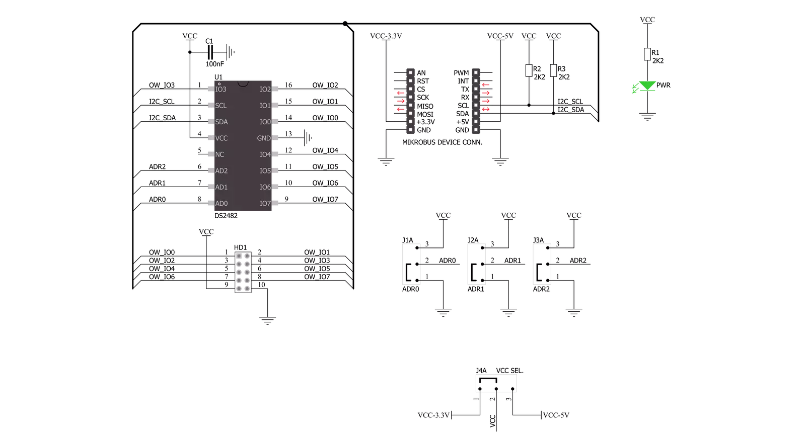
I2C 1-Wire Click is based on the DS2482-800, a self-timed 8-channel 1-Wire master (relative to any attached 1-Wire slave device) from Analog Devices, performing bidirectional conversions between I2C master and 1-Wire slave devices. To optimize 1-Wire waveform generation, the DS2482-800 performs slew-rate control on rising and falling 1-Wire edges. It also has a programmable feature to mask the fast presence pulse edge that some 1-Wire slave devices can generate and programmable strong pull-up features that supports 1-Wire power delivery to 1-Wire devices such as EEPROMs, temperature sensors, and similar devices with momentary high source current modes. The DS2482-800 communicates
with an MCU using the standard I2C 2-Wire interface to read data and configure settings, supporting Fast Mode up to 400kHz. Once supplied with command and data, the I/O controller of the DS2482-800 performs time-critical 1-Wire communication functions such as reset/presence detect cycle, read-byte, write-byte, single-bit R/W and triplet for ROM search without requiring interaction with the host MCU. The host MCU obtains feedback and data (completion of a 1-Wire function, presence pulse, 1-Wire short, search direction taken) through the status and reads data registers. The DS2482-800 has a 7-bit slave address with the first four MSBs fixed to 0011. The address pins, A0, A1, and A2, are programmed
by the user and determine the value of the last three LSBs of the slave address, allowing up to 8 devices to operate on the same bus segment. The value of these address pins can be set by positioning onboard SMD jumpers labeled as I2C ADR to an appropriate position marked as 1 or 0. This Click board™ can operate with both 3.3V and 5V logic voltage levels selected via the PWR SEL jumper. This way, it is allowed for both 3.3V and 5V capable MCUs to use the communication lines properly. However, the Click board™ comes equipped with a library containing easy-to-use functions and an example code that can be used, as a reference, for further development.

Features overview
Development board
The 32L496GDISCOVERY Discovery kit serves as a comprehensive demonstration and development platform for the STM32L496AG microcontroller, featuring an Arm® Cortex®-M4 core. Designed for applications that demand a balance of high performance, advanced graphics, and ultra-low power consumption, this kit enables seamless prototyping for a wide range of embedded solutions. With its innovative energy-efficient
architecture, the STM32L496AG integrates extended RAM and the Chrom-ART Accelerator, enhancing graphics performance while maintaining low power consumption. This makes the kit particularly well-suited for applications involving audio processing, graphical user interfaces, and real-time data acquisition, where energy efficiency is a key requirement. For ease of development, the board includes an onboard ST-LINK/V2-1
debugger/programmer, providing a seamless out-of-the-box experience for loading, debugging, and testing applications without requiring additional hardware. The combination of low power features, enhanced memory capabilities, and built-in debugging tools makes the 32L496GDISCOVERY kit an ideal choice for prototyping advanced embedded systems with state-of-the-art energy efficiency.

Microcontroller Overview
MCU Card / MCU

Architecture
ARM Cortex-M4
MCU Memory (KB)
1024
Silicon Vendor
STMicroelectronics
Pin count
169
RAM (Bytes)
327680
Used MCU Pins
mikroBUS™ mapper
Take a closer look
Click board™ Schematic
Step by step
Project assembly

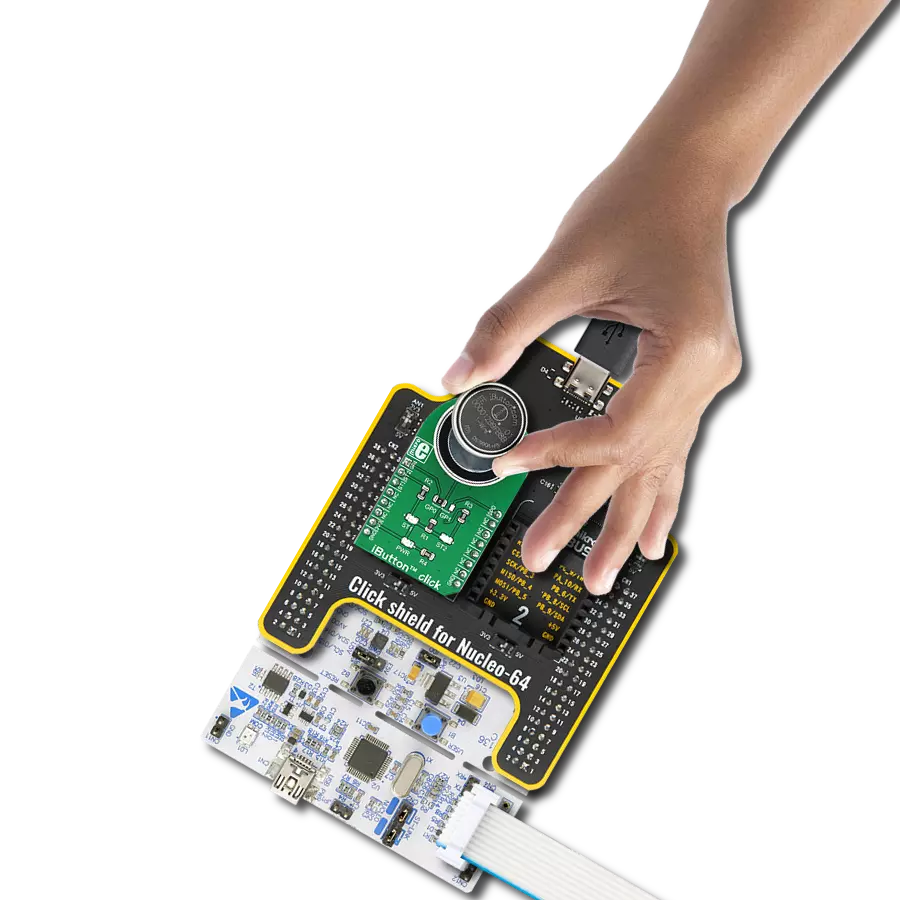
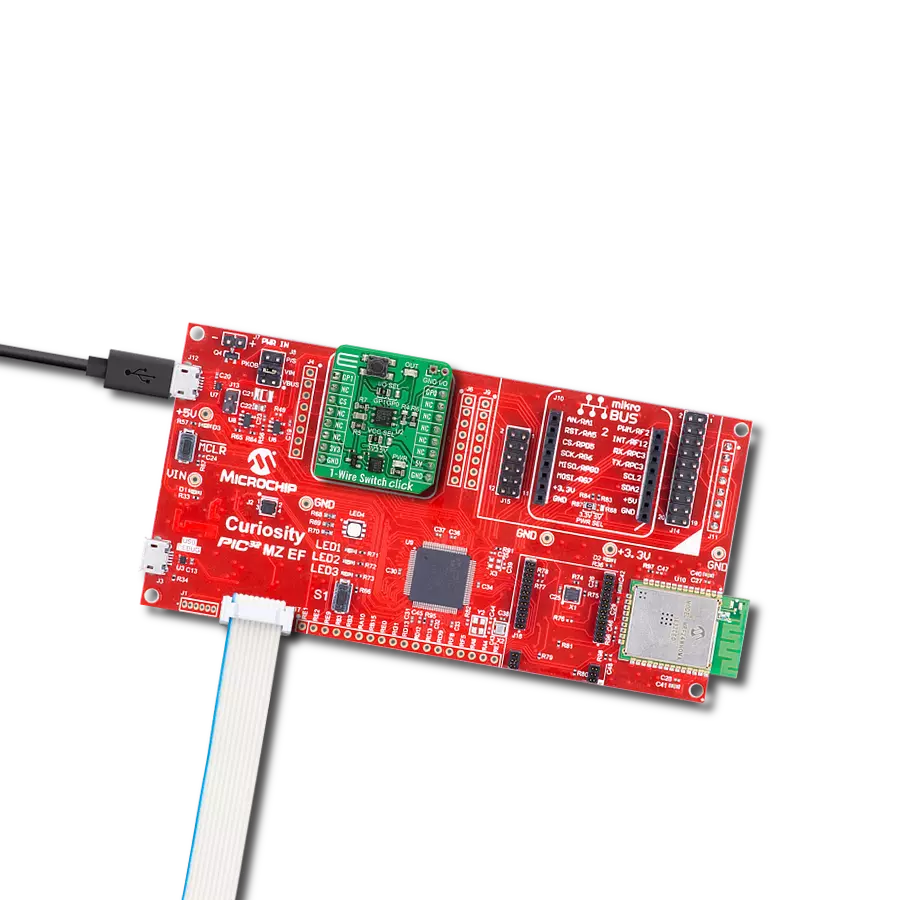
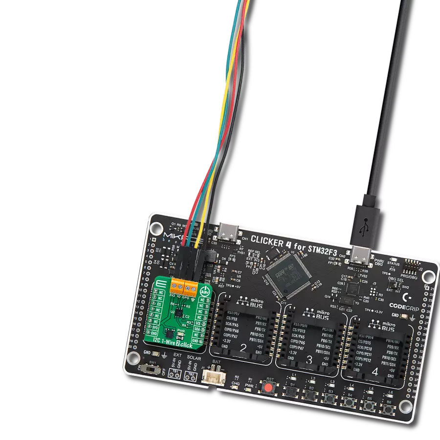
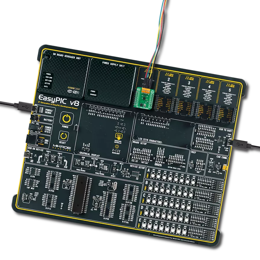
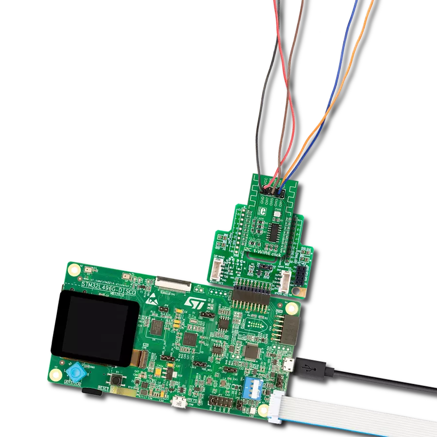
Start by selecting your development board and Click board™. Begin with the Discovery kit with STM32L496AG MCU as your development board.


Software Support
Library Description
This library contains API for I2C 1-Wire Click driver.
Key functions:
i2conewire_setChannel - Set the channel function..
i2conewire_writeByteOneWire - Generic One Wire writes the byte of data function.
i2conewire_readByteOneWire - Generic One Wire read the byte of data function.
Open Source
Code example
The complete application code and a ready-to-use project are available through the NECTO Studio Package Manager for direct installation in the NECTO Studio. The application code can also be found on the MIKROE GitHub account.
/*!
 * \file
 * \brief I2C1Wire Click example
 *
 * # Description
 * This example showcases how to initialize, confiure and use the I2C 1-Wire Click. The Click
 * is a I2C (host) to 1-Wire interface (slave). In order for the example to work one or more
 * 1-Wire (GPIO) Click modules are required. Gnd goes to gnd, power goes to power and the cha-
 * nnels are there to read data from connected modules.
 *
 * The demo application is composed of two sections :
 *
 * ## Application Init
 * This function initializes and configures the logger and Click modules.
 *
 * ## Application Task
 * This function reads all of the channels on the Click module and displays any data it acqu-
 * ires from them with a 100 millisecond delay.
 *
 *
 * \author MikroE Team
 *
 */
// ------------------------------------------------------------------- INCLUDES

#include "board.h"
#include "log.h"
#include "i2c1wire.h"

// ------------------------------------------------------------------ VARIABLES

static i2c1wire_t i2c1wire;
static log_t logger;

// ------------------------------------------------------ APPLICATION FUNCTIONS

void application_init ( )
{
    log_cfg_t log_cfg;
    i2c1wire_cfg_t cfg;

    /**
     * Logger initialization.
     * Default baud rate: 115200
     * Default log level: LOG_LEVEL_DEBUG
     * @note If USB_UART_RX and USB_UART_TX
     * are defined as HAL_PIN_NC, you will
     * need to define them manually for log to work.
     * See @b LOG_MAP_USB_UART macro definition for detailed explanation.
     */
    LOG_MAP_USB_UART( log_cfg );
    log_init( &logger, &log_cfg );
    log_info( &logger, "---- Application Init ----" );

    //  Click initialization.
    i2c1wire_cfg_setup( &cfg );
    I2C1WIRE_MAP_MIKROBUS( cfg, MIKROBUS_1 );
    i2c1wire_init( &i2c1wire, &cfg );
    Delay_1sec( );
}

void application_task ( )
{
    uint8_t chan_state = 0;
    uint8_t cnt_chan = 0;
    uint8_t cnt_val = 0;
    uint8_t id_code[ 9 ] = { 0 };

    chan_state = 1;

    i2c1wire_soft_reset( &i2c1wire );
    Delay_10ms( );
    i2c1wire_set_config( &i2c1wire, I2C1WIRE_CONFIG_1WS_HIGH |
                                    I2C1WIRE_CONFIG_SPU_HIGH |
                                    I2C1WIRE_CONFIG_APU_LOW );
    Delay_10ms( );

    for ( cnt_chan = 0; cnt_chan < 8; cnt_chan++ )
    {
        i2c1wire_set_channel( &i2c1wire, cnt_chan );
        i2c1wire_one_wire_reset( &i2c1wire );
        Delay_10ms( );

        i2c1wire_write_byte_one_wire( &i2c1wire, I2C1WIRE_WIRE_COMMAND_READ_ROM );
        Delay_10ms();

        for ( cnt_val = 8; cnt_val > 0; cnt_val-- )
        {
            id_code[ cnt_val ] = i2c1wire_read_byte_one_wire( &i2c1wire );

            if ( id_code[ cnt_val ] == I2C1WIRE_WIRE_RESULT_OK )
            {
                log_printf( &logger, "\r\n Channel %d : No device on the channel\r\n", ( uint16_t ) cnt_chan );
                Delay_100ms( );
                break;
            }
            else if ( chan_state )
            {
                log_printf( &logger, " Channel %d : ID = 0x", ( uint16_t ) cnt_chan );
                chan_state = 0;
            }

            log_printf( &logger, "%d", ( uint16_t ) id_code[ cnt_val ] );
            Delay_10ms( );
        }

        log_printf( &logger, "\r\n---------------------------------------\r\n" );
    }

    log_printf( &logger, "***\r\n" );
}

int main ( void )
{
    /* Do not remove this line or clock might not be set correctly. */
    #ifdef PREINIT_SUPPORTED
    preinit();
    #endif

    application_init( );

    for ( ; ; )
    {
        application_task( );
    }

    return 0;
}

// ------------------------------------------------------------------------ END
Additional Support
Resources
Category:1-Wire