Integrate USB connectivity into your projects with FT2232 and STM32L496AG
Highly capable USB to serial interface converter
Published Jul 22, 2025
Click board™
FTDI Click
Dev. board
Discovery kit with STM32L496AG MCU
Compiler
NECTO Studio
MCU
STM32L496AG
Achieve high-speed USB 2.0 connectivity to serial interfaces such as UART (Universal Asynchronous Receiver/Transmitter), I2C (Inter-Integrated Circuit), and SPI (Serial Peripheral Interface)
A
A
Hardware Overview
How does it work?
FTDI Click is based on the FT2232H, a 5th-generation high-speed USB to a serial interface converter from FTDI, capable of configuration in various industry standard serial or parallel interfaces. The entire USB protocol is handled on the chip, with no USB-specific firmware programming requirements. Still, it requires USB device drivers for operation, which are free from the official FTDI page. It can work at high speed (480Mbps) and full speed (12Mbps), depending on the usage, alongside a dual Multi-Protocol Synchronous Serial Engine (MPSSE) used to simplify synchronous serial protocol between USB and available interfaces. The FT2232H can communicate with the host MCU over the mikroBUS™ socket using one of the available interfaces (UART, I2C, SPI). The SPI interface can be used as is, while one of the other two has to be selected by the I2C UART jumper, with UART
chosen as a default. Each interface is compatible with an LED indicator marked as TX/RX that signals data transmission. In addition to the communication pins, this board has some additional routed to the RST, PWM, and INT pins of the mikroBUS™ socket and marked as BC0, BC1, and BC2 used for configuration purposes for the MPSSE, or FIFO interface. For additional information on these pins, consult the attached FT2232H datasheet. This Click board™ also features the CAT93C46, a 1K-bit serial EEPROM from Catalyst Semiconductor that can be accessed directly from the FT2232H. The FT2232H uses external EEPROM to configure operational configuration mode and USB description strings. The EEPROM also allows each FTDI channel to be independently configured. It customizes various values and parameters, including remoted Wake Up, power descriptor value, and more. In addition,
FTDI Click features the MCP4921, a 12-bit DAC from Microchip, that communicates with the host MCU over an SPI serial interface of the mikroBUS™ socket. Activated using an FTDI signal over a BD4, it can be used as a reference for external peripherals with a value from the VO pin routed to the AN pin of the mikroBUS™ socket. This Click board™ can be operated only with a 3.3V logic voltage level. Considering that the board can be powered via USB and used as a standalone device, using an additional LDO, the AP7331, in this way, the existence of the voltage of both mikroBUS™ power lines is ensured. The board must complete the proper logic voltage level conversion before use with MCUs with different logic levels. However, the Click board™ comes equipped with a library from FTDI, containing functions and an example code that can be used as a reference for further development.

Features overview
Development board
The 32L496GDISCOVERY Discovery kit serves as a comprehensive demonstration and development platform for the STM32L496AG microcontroller, featuring an Arm® Cortex®-M4 core. Designed for applications that demand a balance of high performance, advanced graphics, and ultra-low power consumption, this kit enables seamless prototyping for a wide range of embedded solutions. With its innovative energy-efficient
architecture, the STM32L496AG integrates extended RAM and the Chrom-ART Accelerator, enhancing graphics performance while maintaining low power consumption. This makes the kit particularly well-suited for applications involving audio processing, graphical user interfaces, and real-time data acquisition, where energy efficiency is a key requirement. For ease of development, the board includes an onboard ST-LINK/V2-1
debugger/programmer, providing a seamless out-of-the-box experience for loading, debugging, and testing applications without requiring additional hardware. The combination of low power features, enhanced memory capabilities, and built-in debugging tools makes the 32L496GDISCOVERY kit an ideal choice for prototyping advanced embedded systems with state-of-the-art energy efficiency.

Microcontroller Overview
MCU Card / MCU

Architecture
ARM Cortex-M4
MCU Memory (KB)
1024
Silicon Vendor
STMicroelectronics
Pin count
169
RAM (Bytes)
327680
Used MCU Pins
mikroBUS™ mapper
Take a closer look
Click board™ Schematic

Step by step
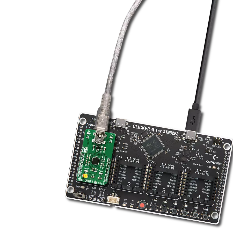
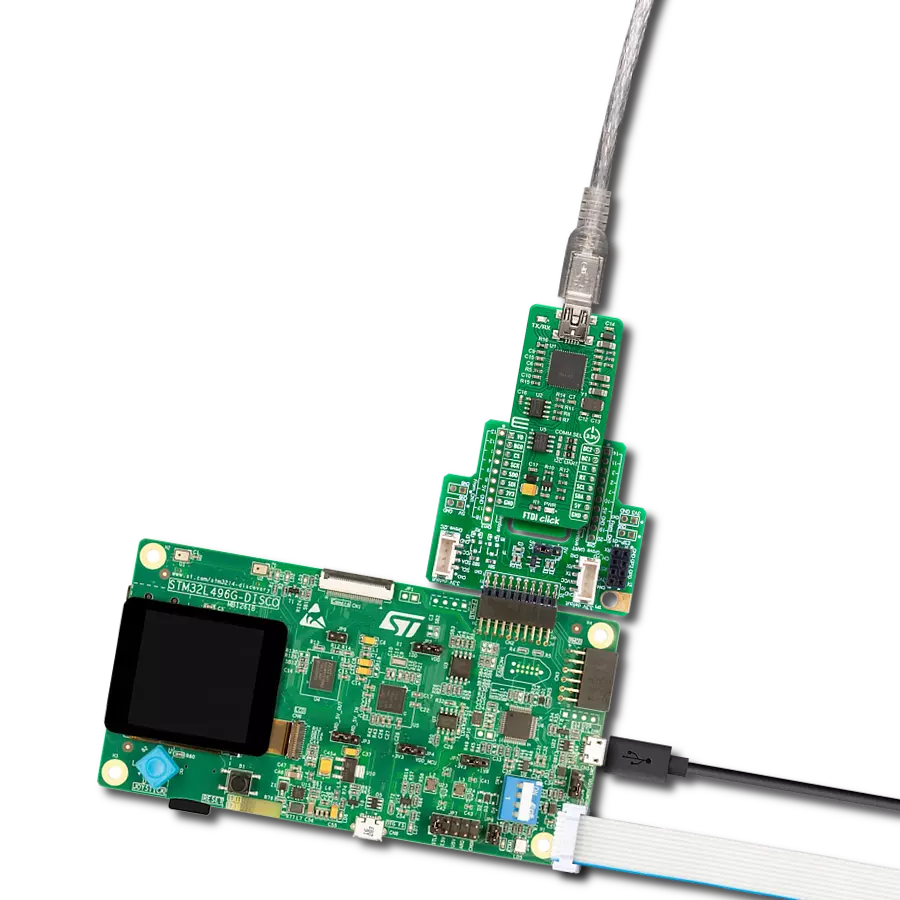
Project assembly

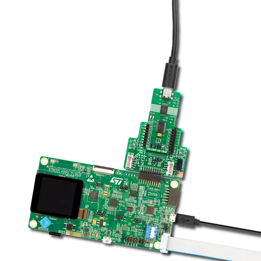
Start by selecting your development board and Click board™. Begin with the Discovery kit with STM32L496AG MCU as your development board.


Track your results in real time
Application Output
1. Application Output - In Debug mode, the 'Application Output' window enables real-time data monitoring, offering direct insight into execution results. Ensure proper data display by configuring the environment correctly using the provided tutorial.

2. UART Terminal - Use the UART Terminal to monitor data transmission via a USB to UART converter, allowing direct communication between the Click board™ and your development system. Configure the baud rate and other serial settings according to your project's requirements to ensure proper functionality. For step-by-step setup instructions, refer to the provided tutorial.

3. Plot Output - The Plot feature offers a powerful way to visualize real-time sensor data, enabling trend analysis, debugging, and comparison of multiple data points. To set it up correctly, follow the provided tutorial, which includes a step-by-step example of using the Plot feature to display Click board™ readings. To use the Plot feature in your code, use the function: plot(*insert_graph_name*, variable_name);. This is a general format, and it is up to the user to replace 'insert_graph_name' with the actual graph name and 'variable_name' with the parameter to be displayed.

Software Support
Library Description
This library contains API for FTDI Click driver.
Key functions:
ftdi_generic_write- This function writes a desired number of data bytes by using UART serial interfaceftdi_generic_read- This function reads a desired number of data bytes by using UART serial interface
Open Source
Code example
The complete application code and a ready-to-use project are available through the NECTO Studio Package Manager for direct installation in the NECTO Studio. The application code can also be found on the MIKROE GitHub account.
/*!
 * @file main.c
 * @brief FTDI Click Example.
 *
 * # Description
 * This example demonstrates the use of FTDI Click by echoing back all the received messages.
 *
 * The demo application is composed of two sections :
 *
 * ## Application Init
 * Initializes the driver and logger.
 *
 * ## Application Task
 * Any data which the host PC sends to the Virtual COM Port (for example, typed into the terminal
 * window in UART Terminal) will be sent over USB to the Click board and then it will be read and
 * echoed back by the MCU to the PC where the terminal program will display it. The data will also
 * be displayed on the USB UART.
 *
 * @author Stefan Filipovic
 *
 */

#include "board.h"
#include "log.h"
#include "ftdi.h"

static ftdi_t ftdi;
static log_t logger;

void application_init ( void )
{
    log_cfg_t log_cfg;  /**< Logger config object. */
    ftdi_cfg_t ftdi_cfg;  /**< Click config object. */

    /**
     * Logger initialization.
     * Default baud rate: 115200
     * Default log level: LOG_LEVEL_DEBUG
     * @note If USB_UART_RX and USB_UART_TX
     * are defined as HAL_PIN_NC, you will
     * need to define them manually for log to work.
     * See @b LOG_MAP_USB_UART macro definition for detailed explanation.
     */
    LOG_MAP_USB_UART( log_cfg );
    log_init( &logger, &log_cfg );
    log_info( &logger, " Application Init " );

    // Click initialization.
    ftdi_cfg_setup( &ftdi_cfg );
    FTDI_MAP_MIKROBUS( ftdi_cfg, MIKROBUS_1 );
    if ( UART_ERROR == ftdi_init( &ftdi, &ftdi_cfg ) )
    {
        log_error( &logger, " Communication init." );
        for ( ; ; );
    }

    log_info( &logger, " Application Task " );
}

void application_task ( void )
{
    uint8_t rx_data = 0;
    if ( ftdi_generic_read ( &ftdi, &rx_data, 1 ) > 0 )
    {
        ftdi_generic_write ( &ftdi, &rx_data, 1 );
        log_printf( &logger, "%c", rx_data );
    }
}

int main ( void )
{
    /* Do not remove this line or clock might not be set correctly. */
    #ifdef PREINIT_SUPPORTED
    preinit();
    #endif

    application_init( );

    for ( ; ; )
    {
        application_task( );
    }

    return 0;
}

// ------------------------------------------------------------------------ END
Additional Support
Resources
Category:USB