Dive into the natural and intuitive HMI world with KMX63 and STM32L031C6
Your path to perfect balance

Published Sep 16, 2023
Click board™
6DOF IMU 11 Click
Dev. board
Fusion for STM32 v8
Compiler
NECTO Studio
MCU
STM32L031C6
Add movement and rotation detection to your projects for unparalleled precision.
A
A
Hardware Overview
How does it work?
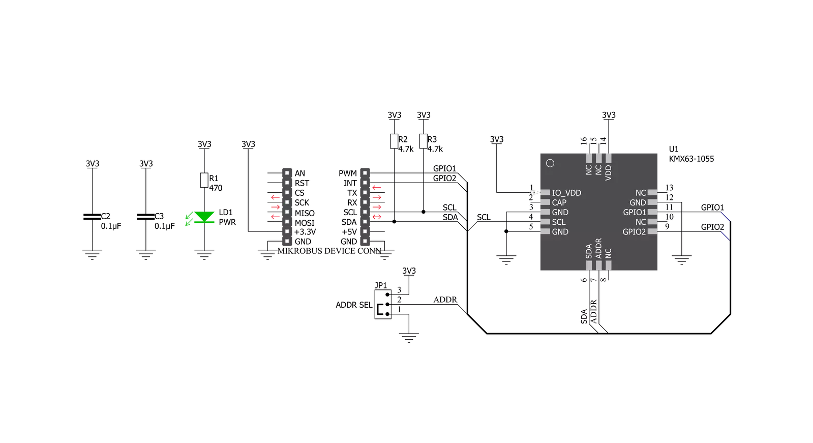
6DOF IMU 11 Click is based on the KMX63, a tri-axis accelerometer, tri-axis magnetometer, and temperature sensor on a single-chip combo solution from Kionix. The Accelerometer and Magnetometer data can be accumulated in an internal 384-byte FIFO buffer and transmitted to the application processor. Acceleration sensing is based on the principle of a differential capacitance arising from acceleration induced motion of the sense element, which utilizes common mode cancellation to decrease errors from process variation, temperature, and environmental stress. Capacitance changes are amplified and converted into digital signals which are processed by a dedicated digital signal processing unit. The digital signal processor applies filtering, bias, and sensitivity adjustments, as well as temperature compensation. Magnetic sensing is based on the principle of magnetic impedance. The magnetic
sensor detects very small magnetic fields by passing an electric pulse through a special electron spin aligned amorphous wire. Due to the high Curie temperature of the wire, the sensor’s thermal performance shows excellent stability. Noise performance is excellent with bias stability over temperature. Bias errors resulting from assembly can be trimmed digitally by the user. These sensors can accept supply voltages between 1.7V and 3.6V, and digital communication voltages from the MCU between 1.2V and 3.6V. The Kionix KMX63 digital sensor can communicate on the I2C digital serial interface bus. This flexibility allows for easy system integration by eliminating analog-to-digital converter requirements and by providing direct communication with system processors. The I2C interface is compliant with high-speed mode, fast mode, and standard mode I2C protocols. With 6DOF IMU 6 click you may
communicate by using I2C serial interface. The I2C is primarily used for serial communication between a Master device and one or more Slave devices. The KMX63 always operates as a Slave device during standard Master-Slave I2C operation. Given all of the possibilities its features offer, the 6DOF IMU 11 click can be used for applications which require movement and orientation features, such as screen orientation, navigation, game playing, machine/vibration analysis, and more. This Click board™ can be operated only with a 3.3V logic voltage level. The board must perform appropriate logic voltage level conversion before using MCUs with different logic levels. Also, it comes equipped with a library containing functions and an example code that can be used as a reference for further development.


Features overview
Development board
Fusion for STM32 v8 is a development board specially designed for the needs of rapid development of embedded applications. It supports a wide range of microcontrollers, such as different 32-bit ARM® Cortex®-M based MCUs from STMicroelectronics, regardless of their number of pins, and a broad set of unique functions, such as the first-ever embedded debugger/programmer over WiFi. The development board is well organized and designed so that the end-user has all the necessary elements, such as switches, buttons, indicators, connectors, and others, in one place. Thanks to innovative manufacturing technology, Fusion for STM32 v8 provides a fluid and immersive working experience, allowing
access anywhere and under any circumstances at any time. Each part of the Fusion for STM32 v8 development board contains the components necessary for the most efficient operation of the same board. An advanced integrated CODEGRIP programmer/debugger module offers many valuable programming/debugging options, including support for JTAG, SWD, and SWO Trace (Single Wire Output)), and seamless integration with the Mikroe software environment. Besides, it also includes a clean and regulated power supply module for the development board. It can use a wide range of external power sources, including a battery, an external 12V power supply, and a power source via the USB Type-C (USB-C) connector.
Communication options such as USB-UART, USB HOST/DEVICE, CAN (on the MCU card, if supported), and Ethernet is also included. In addition, it also has the well-established mikroBUS™ standard, a standardized socket for the MCU card (SiBRAIN standard), and two display options for the TFT board line of products and character-based LCD. Fusion for STM32 v8 is an integral part of the Mikroe ecosystem for rapid development. Natively supported by Mikroe software tools, it covers many aspects of prototyping and development thanks to a considerable number of different Click boards™ (over a thousand boards), the number of which is growing every day.

Microcontroller Overview
MCU Card / MCU
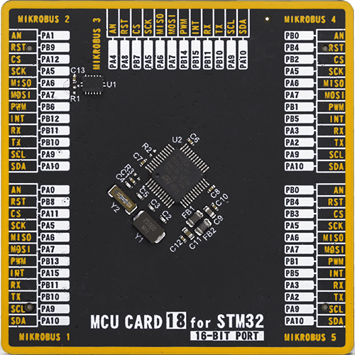
Type
8th Generation
Architecture
ARM Cortex-M0
MCU Memory (KB)
32
Silicon Vendor
STMicroelectronics
Pin count
48
RAM (Bytes)
8192
Used MCU Pins
mikroBUS™ mapper
Take a closer look
Click board™ Schematic
Step by step
Project assembly

Start by selecting your development board and Click board™. Begin with the Fusion for STM32 v8 as your development board.


Track your results in real time
Application Output
1. Application Output - In Debug mode, the 'Application Output' window enables real-time data monitoring, offering direct insight into execution results. Ensure proper data display by configuring the environment correctly using the provided tutorial.

2. UART Terminal - Use the UART Terminal to monitor data transmission via a USB to UART converter, allowing direct communication between the Click board™ and your development system. Configure the baud rate and other serial settings according to your project's requirements to ensure proper functionality. For step-by-step setup instructions, refer to the provided tutorial.

3. Plot Output - The Plot feature offers a powerful way to visualize real-time sensor data, enabling trend analysis, debugging, and comparison of multiple data points. To set it up correctly, follow the provided tutorial, which includes a step-by-step example of using the Plot feature to display Click board™ readings. To use the Plot feature in your code, use the function: plot(*insert_graph_name*, variable_name);. This is a general format, and it is up to the user to replace 'insert_graph_name' with the actual graph name and 'variable_name' with the parameter to be displayed.

Software Support
Library Description
This library contains API for 6DOF IMU 11 Click driver.
Key functions:
c6dofimu11_config_accel- Configuration Accel functionc6dofimu11_config_mag- Configuration Magnetometer functionc6dofimu11_get_axis- Get axis data functionc6dofimu11_get_accel_data- Read Accel X-axis, Y-axis and Z-axis functionc6dofimu11_get_mag_data- Read Magnetometer X-axis, Y-axis and Z-axis functionc6dofimu11_read_accel- Get Accel range X, Y and Z value ( g ) functionc6dofimu11_read_mag- Get Magnetometer magnetic field strength X, Y and Z value ( nT ) function
Open Source
Code example
The complete application code and a ready-to-use project are available through the NECTO Studio Package Manager for direct installation in the NECTO Studio. The application code can also be found on the MIKROE GitHub account.
/*!
 * \file
 * \brief 6DofImu11 Click example
 *
 * # Description
 * Designed to strike a balance between current consumption and noise performance with excellent bias stability over temperature
 *
 * The demo application is composed of two sections :
 *
 * ## Application Init
 * Initialization driver enables - I2C, check device ID, sets default configuration, also write log.
 *
 * ## Application Task
 * This is an example which demonstrates the use of 6DOF IMU 11 Click board.
 * Measured and display Accel and Magnetometer magnetic field
 * strength values for X-axis, Y-axis and Z-axis.
 * Results are being sent to the Uart Terminal where
 * you can track their changes.
 * All data logs write on USB uart changes for every 2 sec.
 *
 * \author MikroE Team
 *
 */
// ------------------------------------------------------------------- INCLUDES

#include "board.h"
#include "log.h"
#include "c6dofimu11.h"

// ------------------------------------------------------------------ VARIABLES

static c6dofimu11_t c6dofimu11;
static log_t logger;

void application_init ( void )
{
    log_cfg_t log_cfg;
    c6dofimu11_cfg_t cfg;

    /**
     * Logger initialization.
     * Default baud rate: 115200
     * Default log level: LOG_LEVEL_DEBUG
     * @note If USB_UART_RX and USB_UART_TX
     * are defined as HAL_PIN_NC, you will
     * need to define them manually for log to work.
     * See @b LOG_MAP_USB_UART macro definition for detailed explanation.
     */
    LOG_MAP_USB_UART( log_cfg );
    log_init( &logger, &log_cfg );
    log_info( &logger, "---- Application Init ----" );

    //  Click initialization.

    c6dofimu11_cfg_setup( &cfg );
    C6DOFIMU11_MAP_MIKROBUS( cfg, MIKROBUS_1 );
    c6dofimu11_init( &c6dofimu11, &cfg );

    if ( c6dofimu11_check_id( &c6dofimu11 ) == C6DOFIMU11_CHECK_ID_SUCCESS )
    {
        log_printf( &logger, "         SUCCESS          \r\n" );
        log_printf( &logger, "--------------------------\r\n" );
    }
    else
    {
        log_printf( &logger, "          ERROR           \r\n" );
        log_printf( &logger, "     Reset the device     \r\n" );
        log_printf( &logger, "--------------------------\r\n" );
        for ( ; ; );
    }

    c6dofimu11_default_cfg(  &c6dofimu11 );

    log_printf( &logger, "    Set default config    \r\n" );
    log_printf( &logger, "--------------------------\r\n" );
    Delay_ms ( 100 );
}

void application_task ( void )
{
   c6dofimu11_mag_t mag_data;
   c6dofimu11_accel_t accel_data;

    c6dofimu11_read_accel ( &c6dofimu11, &accel_data );
    Delay_ms ( 10 );
    c6dofimu11_read_mag ( &c6dofimu11, &mag_data );
    Delay_ms ( 10 );

    log_printf( &logger, " Accel X : %.2f g\r\n", accel_data.x  );

    log_printf( &logger, " Accel Y : %.2f g\r\n", accel_data.y  );

    log_printf( &logger, " Accel Z : %.2f g\r\n", accel_data.z  );


    log_printf( &logger, "\r\n" );


    log_printf( &logger, " Mag X : %.2f uT\r\n", mag_data.x  );

    log_printf( &logger, " Mag Y : %.2f uT\r\n", mag_data.y  );

    log_printf( &logger, " Mag Z : %.2f uT\r\n", mag_data.z  );


    log_printf( &logger, "--------------------------\r\n" );

    Delay_ms ( 1000 );
    Delay_ms ( 1000 );
}

int main ( void )
{
    /* Do not remove this line or clock might not be set correctly. */
    #ifdef PREINIT_SUPPORTED
    preinit();
    #endif

    application_init( );

    for ( ; ; )
    {
        application_task( );
    }

    return 0;
}

// ------------------------------------------------------------------------ END


