Improve your audio experience with KT403A and STM32F302VC
Your favorite tunes, just a click away
Published Jul 22, 2025
Click board™
MP3 2 Click
Dev. board
CLICKER 4 for STM32F302VCT6
Compiler
NECTO Studio
MCU
STM32F302VC
Our cutting-edge MP3 solution empowers you to immerse yourself in the world of music with unparalleled clarity and convenience. It's your ultimate companion for enjoying your favorite tunes anytime, anywhere.
A
A
Hardware Overview
How does it work?
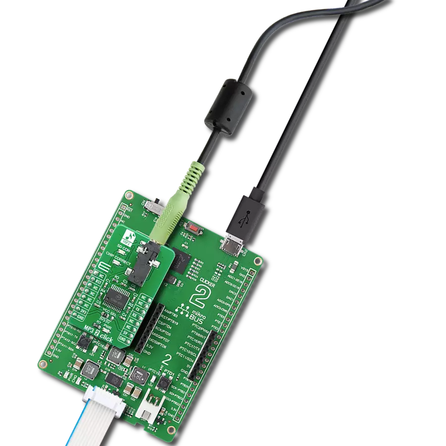
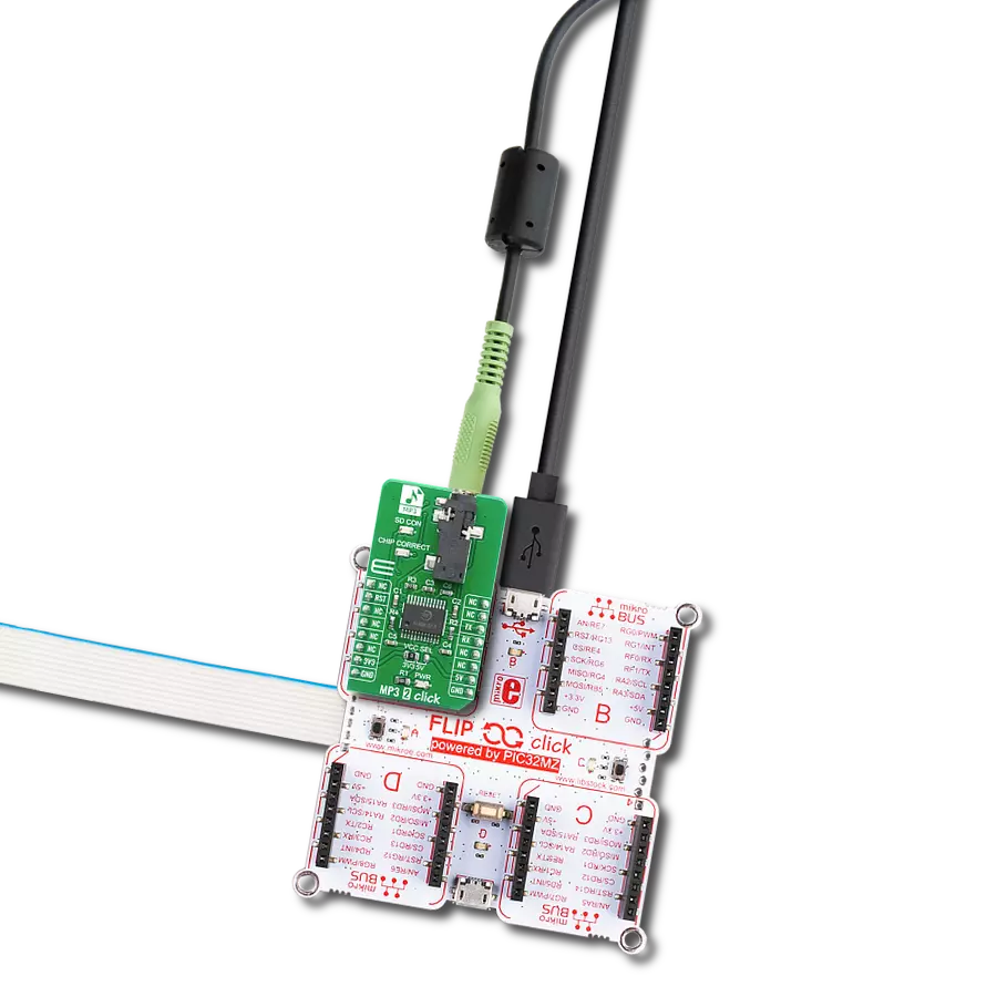
MP3 2 Click is based on the KT403A, a SOC chip solution with intergraded MCU, hardware audio MP3/WAV decoder and DSP, from Shenzhen Qianle Microelectronics Technology, as a main integrated circuit, micro SD card connector, and 3.5mm Audio Jack connector. Basically, it is a complete solution for a DAP (digital audio player) on a Click board, which can be controlled over the UART communication interface, using RX and TX pins of the mikroBUS™ socket. The default baud rate is 9600bps and it is customizable. On the MP3 2 Click, KT403A serves as a brain. It is complete SOC, which integrates16-bit MCU, audio decoder, and a 24-bit DSP. It also integrates the complete SD card interface and therefore, this click board
contains the connector onboard for an external micro SD card. Thanks to that, the user can insert a fair amount of memory if the long, continuous playback time is needed. MP3 2 Click has two status indication LEDs, onboard. The first one is named “SD Card” and it serves as an indication that the SD Card is present in the slot. The other one is “Chip Correct” and it indicates that the SD Card is correct and that the communication between the KT403A and the SD Card sucseeded. Besides the indicatora, there is one 3.5mm headphone jack onboard, so that MP3 2 Click can be connected directly to the next stage of the music playback system, ie. audio amplifier. Using the predefined command set, MP3 2 Click can be
fully controlled. One can Play/Pause a song, play a specific track, change a Volume Up and Volume Down between 0% and 100%, play the next or the previous song, repeat the current song, and more. Besides that, several sound effects are also supported, mentioned for different types of music: Normal, Jazz, Classic, Pop, and Rock. This Click board™ can operate with either 3.3V or 5V logic voltage levels selected via the VCC SEL jumper. This way, both 3.3V and 5V capable MCUs can use the communication lines properly. Also, this Click board™ comes equipped with a library containing easy-to-use functions and an example code that can be used as a reference for further development.

Features overview
Development board
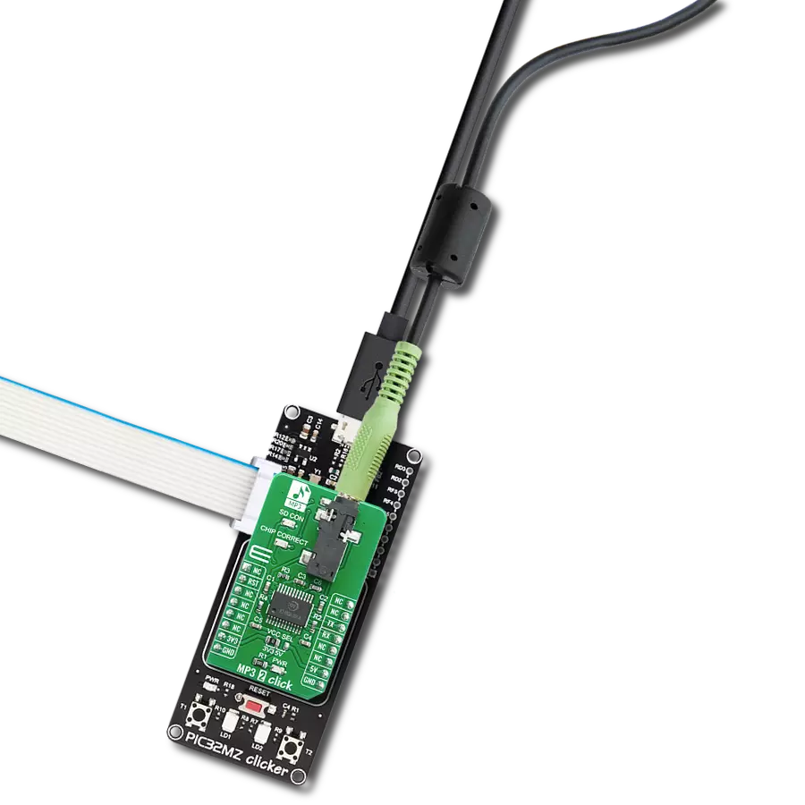
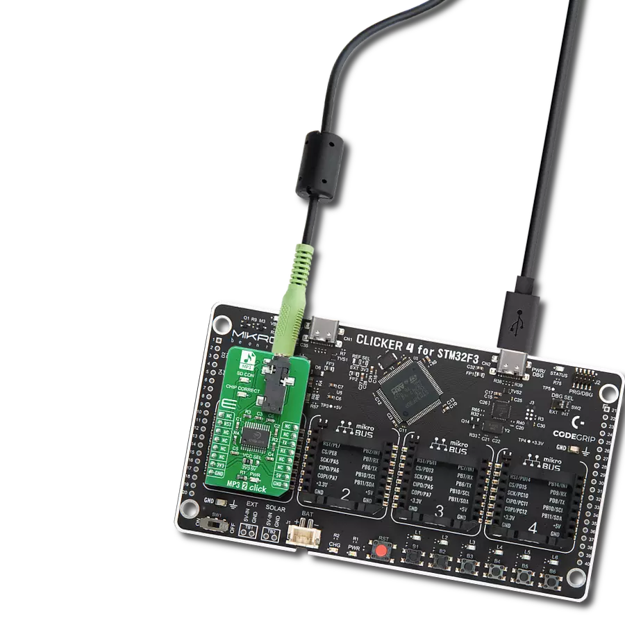
Clicker 4 for STM32F3 is a compact development board designed as a complete solution, you can use it to quickly build your own gadgets with unique functionalities. Featuring a STM32F302VCT6, four mikroBUS™ sockets for Click boards™ connectivity, power managment, and more, it represents a perfect solution for the rapid development of many different types of applications. At its core, there is a STM32F302VCT6 MCU, a powerful microcontroller by STMicroelectronics, based on the high-
performance Arm® Cortex®-M4 32-bit processor core operating at up to 168 MHz frequency. It provides sufficient processing power for the most demanding tasks, allowing Clicker 4 to adapt to any specific application requirements. Besides two 1x20 pin headers, four improved mikroBUS™ sockets represent the most distinctive connectivity feature, allowing access to a huge base of Click boards™, growing on a daily basis. Each section of Clicker 4 is clearly marked, offering an intuitive and clean interface. This makes working with the development
board much simpler and thus, faster. The usability of Clicker 4 doesn’t end with its ability to accelerate the prototyping and application development stages: it is designed as a complete solution which can be implemented directly into any project, with no additional hardware modifications required. Four mounting holes [4.2mm/0.165”] at all four corners allow simple installation by using mounting screws. For most applications, a nice stylish casing is all that is needed to turn the Clicker 4 development board into a fully functional, custom design.

Microcontroller Overview
MCU Card / MCU

Architecture
ARM Cortex-M4
MCU Memory (KB)
256
Silicon Vendor
STMicroelectronics
Pin count
100
RAM (Bytes)
40960
Used MCU Pins
mikroBUS™ mapper
Take a closer look
Click board™ Schematic

Step by step
Project assembly

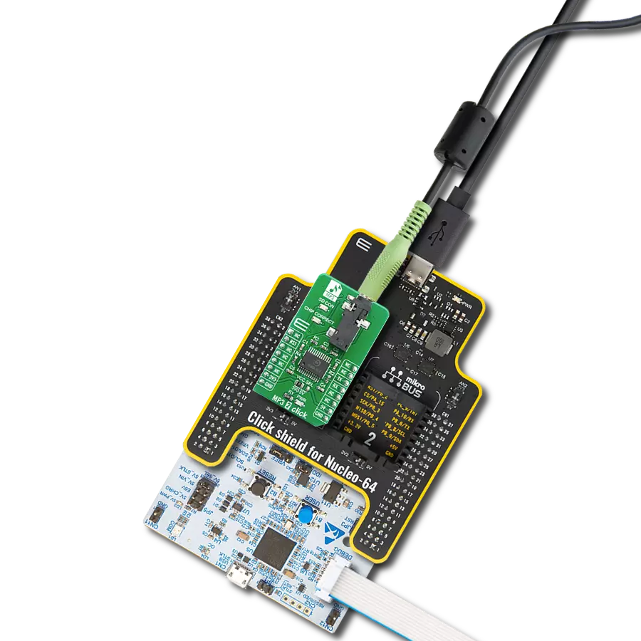
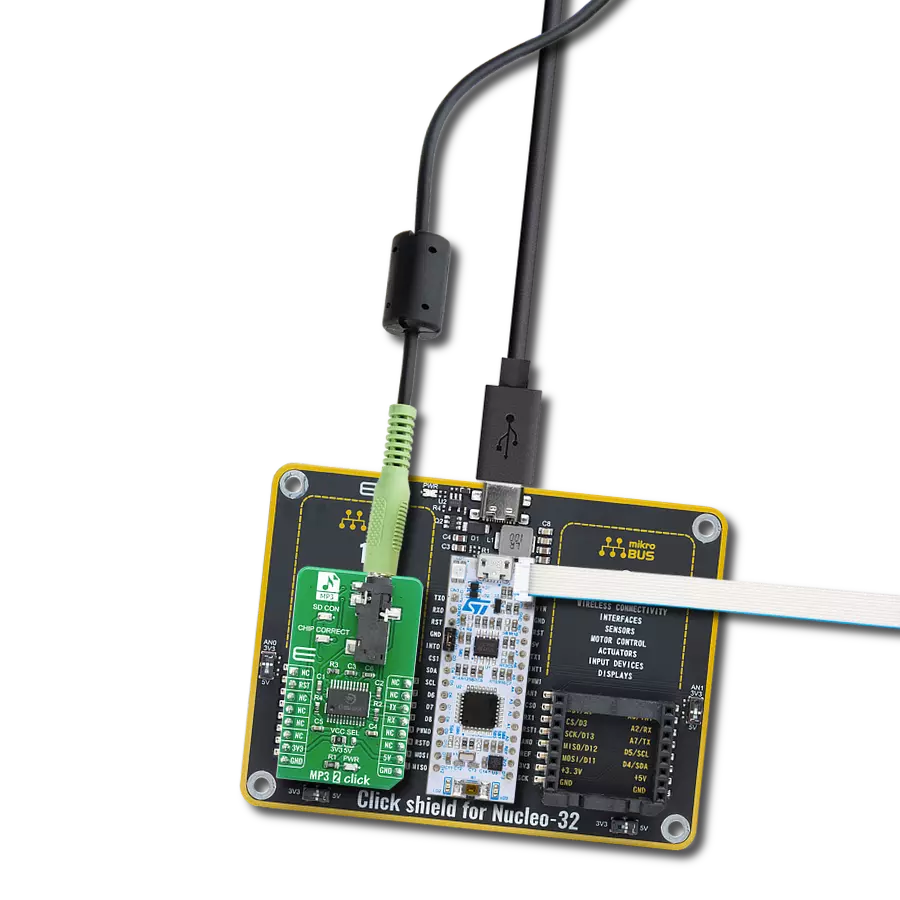
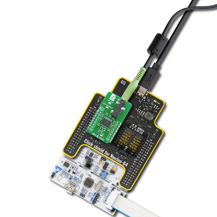
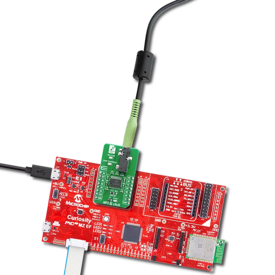
Start by selecting your development board and Click board™. Begin with the CLICKER 4 for STM32F302VCT6 as your development board.


Software Support
Library Description
This library contains API for MP3 2 Click driver.
Key functions:
mp32_hw_reset- Reset the device functionmp32_rx_cmd- Received response data functionmp32_tx_cmd- Write command function.
Open Source
Code example
The complete application code and a ready-to-use project are available through the NECTO Studio Package Manager for direct installation in the NECTO Studio. The application code can also be found on the MIKROE GitHub account.
/*!
 * \file
 * \brief Mp32 Click example
 *
 * # Description
 * This example demonstates the use of MP3 2 Click board.
 *
 * The demo application is composed of two sections :
 *
 * ## Application Init
 * Initializes the driver and enables the Click board.
 * Then sets the device to play songs from SD Card, and after that sets volume, and equalizer.
 *
 * ## Application Task
 * Demonstrates the use of play, play next, and pause modes.
 * Each step will be logged on the USB UART where you can track the program flow.
 *
 * @note
 * A valid microSD Card that contains at least one mp3 sound on it needs to be
 * inserted into the Click board.
 *
 * \author MikroE Team
 *
 */
// ------------------------------------------------------------------- INCLUDES

#include "board.h"
#include "log.h"
#include "mp32.h"
#include "string.h"

// ------------------------------------------------------------------ VARIABLES

static mp32_t mp32;
static log_t logger;

// ------------------------------------------------------ APPLICATION FUNCTIONS

void application_init ( void )
{
    log_cfg_t log_cfg;
    mp32_cfg_t cfg;

    /**
     * Logger initialization.
     * Default baud rate: 115200
     * Default log level: LOG_LEVEL_DEBUG
     * @note If USB_UART_RX and USB_UART_TX
     * are defined as HAL_PIN_NC, you will
     * need to define them manually for log to work.
     * See @b LOG_MAP_USB_UART macro definition for detailed explanation.
     */
    LOG_MAP_USB_UART( log_cfg );
    log_init( &logger, &log_cfg );
    log_info( &logger, "---- Application Init ----" );

    //  Click initialization.

    mp32_cfg_setup( &cfg );
    MP32_MAP_MIKROBUS( cfg, MIKROBUS_1 );
    mp32_init( &mp32, &cfg );

    Delay_ms ( 500 );

    log_printf( &logger, "-------------------------\r\n" );
    log_printf( &logger, "       MP3 2 Click       \r\n" );
    log_printf( &logger, "-------------------------\r\n" );
    Delay_100ms( );

    mp32_hw_reset( &mp32 );
    Delay_ms ( 100 );

    mp32_set_device( &mp32, MP32_SDCARD );
    mp32_set_volume( &mp32, 50 );
    mp32_set_eq( &mp32, MP32_EQ_NORMAL );
    Delay_ms ( 100 );
}

void application_task ( void )
{
    log_printf( &logger, " >>> Play\r\n" );
    mp32_play_mode( &mp32 );
    // 10 seconds delay
    Delay_ms ( 1000 );
    Delay_ms ( 1000 );
    Delay_ms ( 1000 );
    Delay_ms ( 1000 );
    Delay_ms ( 1000 );
    Delay_ms ( 1000 );
    Delay_ms ( 1000 );
    Delay_ms ( 1000 );
    Delay_ms ( 1000 );
    Delay_ms ( 1000 );
    log_printf( &logger, " >>> Next song\r\n" );
    mp32_play_next( &mp32 );
    // 10 seconds delay
    Delay_ms ( 1000 );
    Delay_ms ( 1000 );
    Delay_ms ( 1000 );
    Delay_ms ( 1000 );
    Delay_ms ( 1000 );
    Delay_ms ( 1000 );
    Delay_ms ( 1000 );
    Delay_ms ( 1000 );
    Delay_ms ( 1000 );
    Delay_ms ( 1000 );
    log_printf( &logger, " >>> Pause\r\n" );
    mp32_pause_mode( &mp32 );
    Delay_ms ( 1000 );
    Delay_ms ( 1000 );
    Delay_ms ( 1000 );
}

int main ( void )
{
    /* Do not remove this line or clock might not be set correctly. */
    #ifdef PREINIT_SUPPORTED
    preinit();
    #endif

    application_init( );

    for ( ; ; )
    {
        application_task( );
    }

    return 0;
}


// ------------------------------------------------------------------------ END
Additional Support
Resources
Category:MP3