Unlock new outdoor adventures using L76 and STM32F302VC
Your passport to seamless navigation!

Published Jul 22, 2025
Click board™
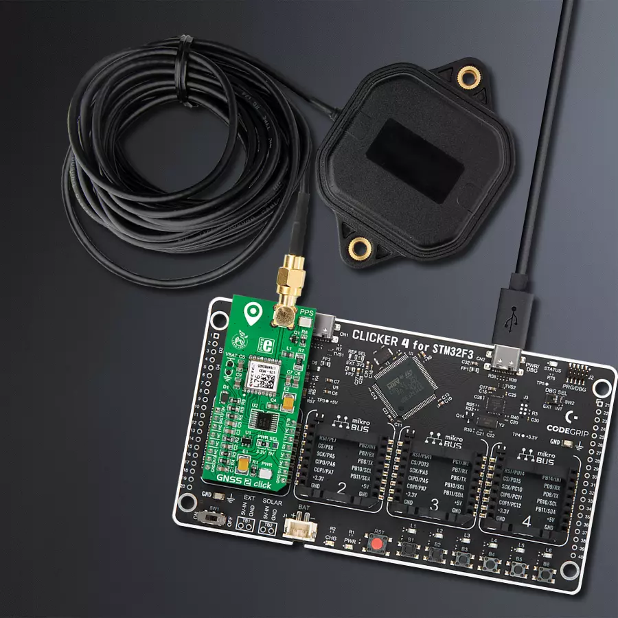
GNSS2 Click
Dev. board
CLICKER 4 for STM32F302VCT6
Compiler
NECTO Studio
MCU
STM32F302VC
Get ahead of the competition and build navigation systems to enhance your products and services
A
A
Hardware Overview
How does it work?
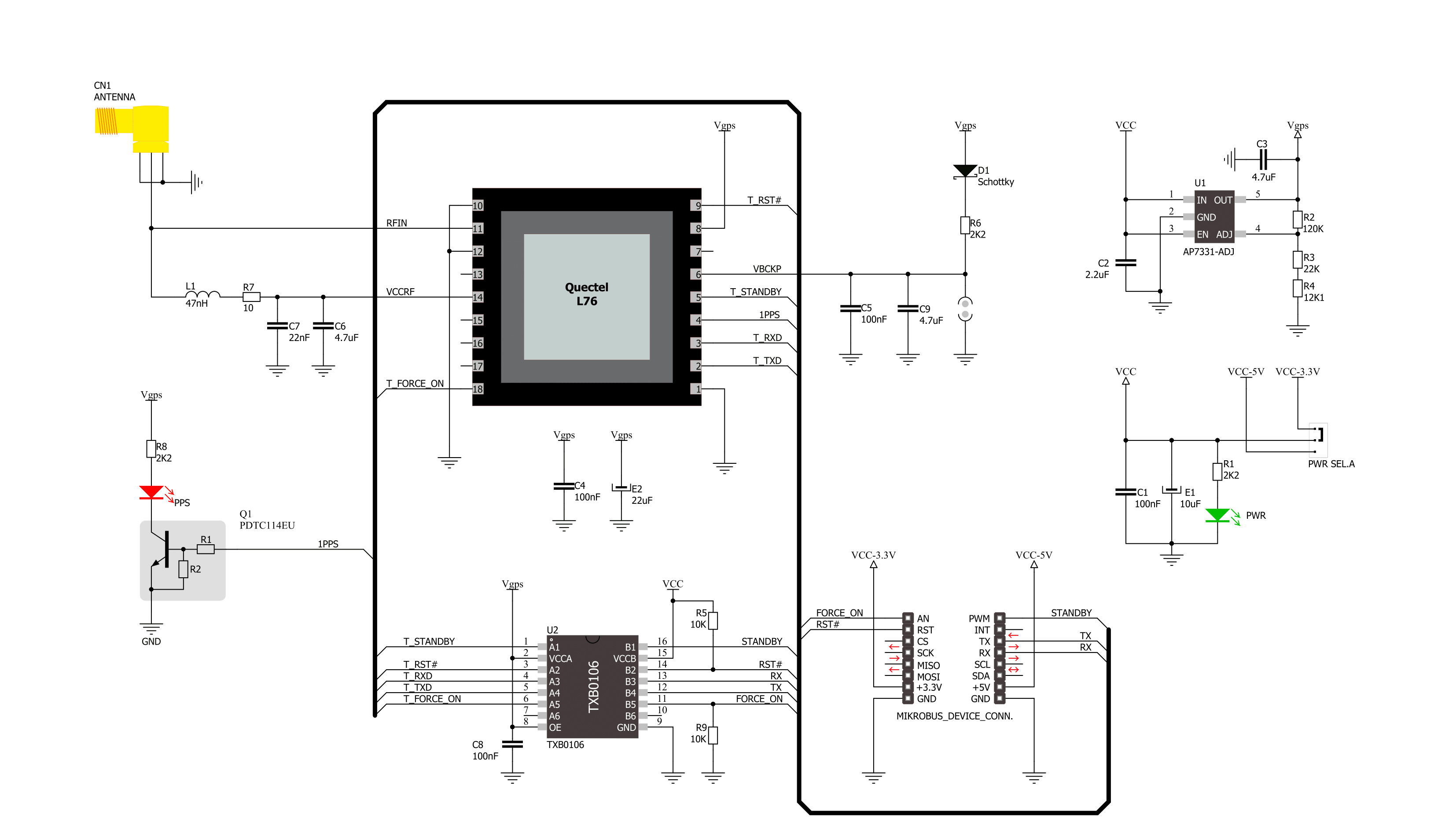
GNSS2 Click is based on the L76, a compact GNSS module from Quectel Wireless Solutions. The L76 supports the L1 band only (1575.42MHz) with tracking 33 channels, 99 acquisition channels, and 210 PRN channels. It can also acquire and track any mix of multiple satellite signals. The module is an ultra-low tracking power consumption device with a high sensitivity of -165dBm while tracking and -148dBm in acquisition mode with a less than 1-second reacquisition time. The greater number of visible satellites increases positioning accuracy (<2.5m CEP) and decreases acquisition time (<5s TTFF with a warm start). GNSS 2 Click supports anti-jamming and better positioning under weak signal conditions with onboard LNA, multi-tone active interference canceller, and balloon mode for high altitudes up to 80km. The L76 can automatically predict satellite orbits from data stored in its internal flash (EASY™ technology), and it can adaptively adjust its ON/OFF time to balance positioning accuracy and power
consumption (AlwaysLocate™ technology). To save power consumption, GNSS2 Click comes with a VBAT connector for connecting an external power supply which can supply power to the module’s SRAM memory. This memory serves for storing GPS information for quick Start-Up sequences. Periodic standby mode can control the power on/off time of GNSS2 Click periodically to reduce average power consumption, and on/off time can be configured using the PMTK command. GNSS2 Click will enter the periodic mode after successfully fixing the position. For communication with the host microcontroller, L76 uses the UART interface with commonly used UART RX and TX pins as its default communication protocol operating at 9600bps by default configuration to transmit and exchange data. In addition, the Click board™ features some other functions accessible through mikroBUS™ signals, such as Force on (FON), Reset (RST), and Standby (STB). Logic high state on FON will force the
module to be woken up from Backup mode, while the RST pin provides a general reset feature. The STB pin can put the module into or exit from Standby mode. In addition to precise positioning, the GNSS 2 Click also has an accurate timing signal indicated via a red LED indicator marked as PPS and an SMA antenna connector used to connect the appropriate active antenna that MIKROE has in its offer, for improved range and received signal strength. This Click board™ can operate with either 3.3V or 5V logic voltage levels selected via the PWR SEL jumper. An appropriate voltage level translator performs a proper logic voltage level conversion, while the onboard LDO, the AP7331, ensures the recommended voltage levels power module. However, the Click board™ comes equipped with a library containing easy-to-use functions and an example code that can be used, as a reference, for further development.

Features overview
Development board
Clicker 4 for STM32F3 is a compact development board designed as a complete solution, you can use it to quickly build your own gadgets with unique functionalities. Featuring a STM32F302VCT6, four mikroBUS™ sockets for Click boards™ connectivity, power managment, and more, it represents a perfect solution for the rapid development of many different types of applications. At its core, there is a STM32F302VCT6 MCU, a powerful microcontroller by STMicroelectronics, based on the high-
performance Arm® Cortex®-M4 32-bit processor core operating at up to 168 MHz frequency. It provides sufficient processing power for the most demanding tasks, allowing Clicker 4 to adapt to any specific application requirements. Besides two 1x20 pin headers, four improved mikroBUS™ sockets represent the most distinctive connectivity feature, allowing access to a huge base of Click boards™, growing on a daily basis. Each section of Clicker 4 is clearly marked, offering an intuitive and clean interface. This makes working with the development
board much simpler and thus, faster. The usability of Clicker 4 doesn’t end with its ability to accelerate the prototyping and application development stages: it is designed as a complete solution which can be implemented directly into any project, with no additional hardware modifications required. Four mounting holes [4.2mm/0.165”] at all four corners allow simple installation by using mounting screws. For most applications, a nice stylish casing is all that is needed to turn the Clicker 4 development board into a fully functional, custom design.

Microcontroller Overview
MCU Card / MCU

Architecture
ARM Cortex-M4
MCU Memory (KB)
256
Silicon Vendor
STMicroelectronics
Pin count
100
RAM (Bytes)
40960
You complete me!
Accessories
GNSS Active External Antenna is a unique multi-band type of antenna coming from u-Blox that is the perfect selection for high precision GNSS applications, which require highly accurate location abilities such as RTK. The ANN-MB-00 is a multi-band (L1, L2/E5b/B2I) active GNSS antenna with a 5m cable and SMA connector. The antenna supports GPS, GLONASS, Galileo, and BeiDou and includes a high-performance multi-band RHCP dual-feed patch antenna element, a built-in high-gain LNA with SAW pre-filtering, and a 5 m antenna cable with SMA connector, and is waterproof.

Used MCU Pins
mikroBUS™ mapper
Take a closer look
Click board™ Schematic
Step by step
Project assembly

Start by selecting your development board and Click board™. Begin with the CLICKER 4 for STM32F302VCT6 as your development board.


Software Support
Library Description
This library contains API for GNSS2 Click driver.
Key functions:
gnss2_generic_read- This function reads a desired number of data bytes by using UART serial interfacegnss2_clear_ring_buffers- This function clears UART tx and rx ring buffersgnss2_parse_gpgga- This function parses the GPGGA data from the read response buffer
Open Source
Code example
The complete application code and a ready-to-use project are available through the NECTO Studio Package Manager for direct installation in the NECTO Studio. The application code can also be found on the MIKROE GitHub account.
/*!
 * @file main.c
 * @brief GNSS 2 Click Example.
 *
 * # Description
 * This example demonstrates the use of GNSS 2 Click by reading and displaying
 * the GPS coordinates.
 *
 * The demo application is composed of two sections :
 *
 * ## Application Init
 * Initializes the driver and logger.
 *
 * ## Application Task
 * Reads the received data, parses the GPGGA info from it, and once it receives the position fix
 * it will start displaying the coordinates on the USB UART.
 *
 * ## Additional Function
 * - static void gnss2_clear_app_buf ( void )
 * - static err_t gnss2_process ( gnss2_t *ctx )
 * - static void gnss2_parser_application ( char *rsp )
 *
 * @author Stefan Filipovic
 *
 */

#include "board.h"
#include "log.h"
#include "gnss2.h"
#include "string.h"

#define PROCESS_BUFFER_SIZE 200

static gnss2_t gnss2;
static log_t logger;

static char app_buf[ PROCESS_BUFFER_SIZE ] = { 0 };
static int32_t app_buf_len = 0;

/**
 * @brief GNSS 2 clearing application buffer.
 * @details This function clears memory of application buffer and reset its length.
 * @return None.
 * @note None.
 */
static void gnss2_clear_app_buf ( void );

/**
 * @brief GNSS 2 data reading function.
 * @details This function reads data from device and concatenates data to application buffer.
 * @param[in] ctx : Click context object.
 * See #gnss2_t object definition for detailed explanation.
 * @return @li @c  0 - Read some data.
 *         @li @c -1 - Nothing is read.
 * See #err_t definition for detailed explanation.
 * @note None.
 */
static err_t gnss2_process ( gnss2_t *ctx );

/**
 * @brief GNSS 2 parser application function.
 * @details This function parses GNSS data and logs it on the USB UART. It clears app and ring buffers
 * after successfully parsing data.
 * @param[in] ctx : Click context object.
 * See #gnss2_t object definition for detailed explanation.
 * @param[in] rsp Response buffer.
 * @return None.
 * @note None.
 */
static void gnss2_parser_application ( gnss2_t *ctx, char *rsp );

void application_init ( void )
{
    log_cfg_t log_cfg;  /**< Logger config object. */
    gnss2_cfg_t gnss2_cfg;  /**< Click config object. */

    /**
     * Logger initialization.
     * Default baud rate: 115200
     * Default log level: LOG_LEVEL_DEBUG
     * @note If USB_UART_RX and USB_UART_TX
     * are defined as HAL_PIN_NC, you will
     * need to define them manually for log to work.
     * See @b LOG_MAP_USB_UART macro definition for detailed explanation.
     */
    LOG_MAP_USB_UART( log_cfg );
    log_init( &logger, &log_cfg );
    log_info( &logger, " Application Init " );

    // Click initialization.
    gnss2_cfg_setup( &gnss2_cfg );
    GNSS2_MAP_MIKROBUS( gnss2_cfg, MIKROBUS_1 );
    if ( UART_ERROR == gnss2_init( &gnss2, &gnss2_cfg ) )
    {
        log_error( &logger, " Communication init." );
        for ( ; ; );
    }
    log_info( &logger, " Application Task " );
}

void application_task ( void )
{
    if ( GNSS2_OK == gnss2_process( &gnss2 ) )
    {
        if ( PROCESS_BUFFER_SIZE == app_buf_len )
        {
            gnss2_parser_application( &gnss2, app_buf );
        }
    }
}

int main ( void )
{
    /* Do not remove this line or clock might not be set correctly. */
    #ifdef PREINIT_SUPPORTED
    preinit();
    #endif

    application_init( );

    for ( ; ; )
    {
        application_task( );
    }

    return 0;
}

static void gnss2_clear_app_buf ( void )
{
    memset( app_buf, 0, app_buf_len );
    app_buf_len = 0;
}

static err_t gnss2_process ( gnss2_t *ctx )
{
    char rx_buf[ PROCESS_BUFFER_SIZE ] = { 0 };
    int32_t rx_size = 0;
    rx_size = gnss2_generic_read( ctx, rx_buf, PROCESS_BUFFER_SIZE );
    if ( rx_size > 0 )
    {
        int32_t buf_cnt = app_buf_len;
        if ( ( ( app_buf_len + rx_size ) > PROCESS_BUFFER_SIZE ) && ( app_buf_len > 0 ) )
        {
            buf_cnt = PROCESS_BUFFER_SIZE - ( ( app_buf_len + rx_size ) - PROCESS_BUFFER_SIZE );
            memmove ( app_buf, &app_buf[ PROCESS_BUFFER_SIZE - buf_cnt ], buf_cnt );
        }
        for ( int32_t rx_cnt = 0; rx_cnt < rx_size; rx_cnt++ )
        {
            if ( rx_buf[ rx_cnt ] )
            {
                app_buf[ buf_cnt++ ] = rx_buf[ rx_cnt ];
                if ( app_buf_len < PROCESS_BUFFER_SIZE )
                {
                    app_buf_len++;
                }
            }
        }
        return GNSS2_OK;
    }
    return GNSS2_ERROR;
}

static void gnss2_parser_application ( gnss2_t *ctx, char *rsp )
{
    char element_buf[ 100 ] = { 0 };
    if ( GNSS2_OK == gnss2_parse_gpgga( rsp, GNSS2_GPGGA_LATITUDE, element_buf ) )
    {
        static uint8_t wait_for_fix_cnt = 0;
        if ( strlen( element_buf ) > 0 )
        {
            log_printf( &logger, "\r\n Latitude: %.2s degrees, %s minutes \r\n", element_buf, &element_buf[ 2 ] );
            gnss2_parse_gpgga( rsp, GNSS2_GPGGA_LONGITUDE, element_buf );
            log_printf( &logger, " Longitude: %.3s degrees, %s minutes \r\n", element_buf, &element_buf[ 3 ] );
            memset( element_buf, 0, sizeof( element_buf ) );
            gnss2_parse_gpgga( rsp, GNSS2_GPGGA_ALTITUDE, element_buf );
            log_printf( &logger, " Altitude: %s m \r\n", element_buf );
            wait_for_fix_cnt = 0;
        }
        else
        {
            if ( wait_for_fix_cnt % 5 == 0 )
            {
                log_printf( &logger, " Waiting for the position fix...\r\n\n" );
                wait_for_fix_cnt = 0;
            }
            wait_for_fix_cnt++;
        }
        gnss2_clear_ring_buffers( ctx );
        gnss2_clear_app_buf( );
    }
}

// ------------------------------------------------------------------------ END
Additional Support
Resources
Category:GPS/GNSS


