Elevate your network game with LARA-R2's multiband magic and STM32F429NI
One modem, multiple possibilities

Published Sep 09, 2023
Click board™
4G LTE-AT&T Click (for North America)
Dev. board
UNI-DS v8
Compiler
NECTO Studio
MCU
STM32F429NI
With a focus on high-speed cellular networking and communication needs in North America, our solution offers a comprehensive suite of features, including network indication, embedded TCP/UDP stack, HTTP and HTTPS transfer protocols, and IPv4/IPv6 dual-stack support
A
A
Hardware Overview
How does it work?
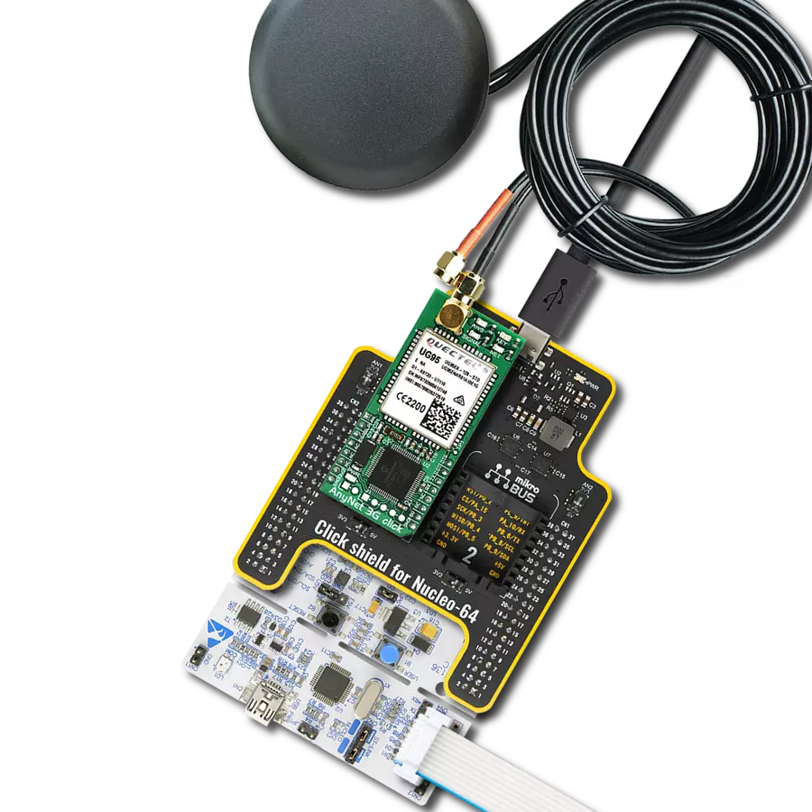
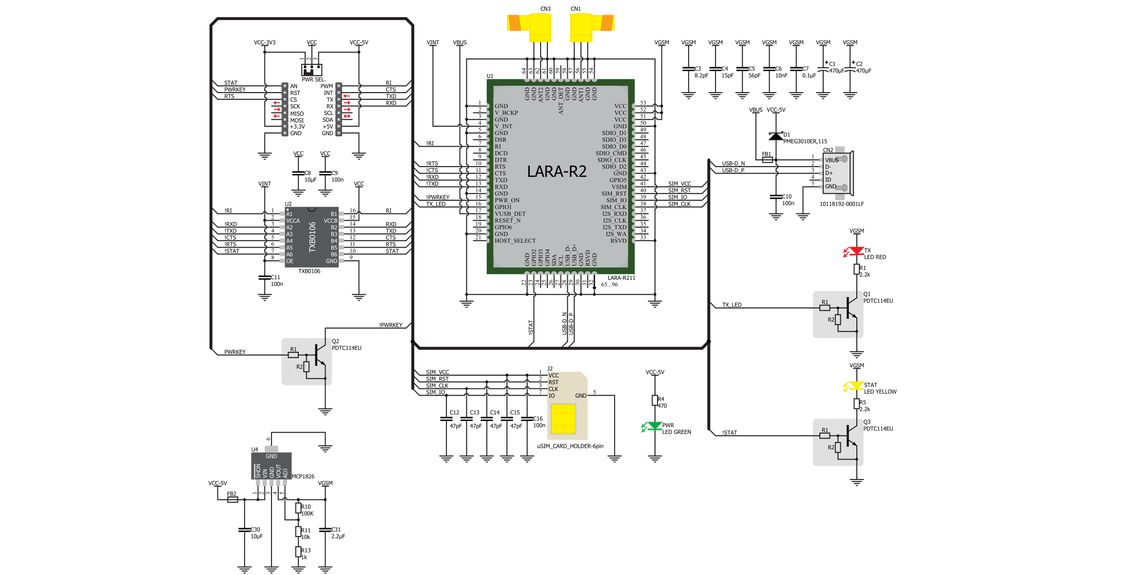
4G LTE AT&T Click is based on the LARA-R202 series modem from Trasna. Several click boards cover different regions using different modules: North America - Verizon featuring LARA-R204, North America – AT&T featuring LARA-R202, Asia Pacific featuring LARA-R280, Europe featuring LARA-R211. The main difference between these modules is the supported frequency bands, which comply with each region's regulations. A complete list of supported bands for each module and other relevant info about the module itself can be found in the LARA-R2 series modem datasheet. LARA-R2 series modem is the main component of the click board, and it consists of several internal blocks or sections, such as antenna switching and signal conditioning section, RF transceiver section, memory, power management, and most importantly - the cellular baseband processor. This section contains the logic necessary for managing the other sections and provides the interface to the host MCU. This interface comprises several lines that report the antenna status, sim card status, UART interface lines, reset line, USB interface lines, and more. These lines are routed to the respective elements of the click board. The LARA-R2 series module has to be powered with a clean and stable power supply. The voltage needed for the module to work properly is about 4V, and it is derived from the 5V mikroBUS™ rail through the MCP1826, a 1A low drop output (LDO) regulator from Microchip. Although the LARA-R2 series module is a low-power device, the cellular
network modules, in general, are notorious for their high power consumption, so the 1A LDO had to be used. Digital sections of the LARA-R2 series are internally supplied by 1.8V, so it is necessary to condition the communication bus lines that connect the host MCU with the module. For this reason, another small LDO is used, providing the needed reference voltage for one side of the TXB0106, a 6-bit bidirectional level shifting and voltage translator with automatic direction sensing from Texas Instruments. The reference voltage for the other side of the level shifter is taken from the onboard SMD jumper, labeled as PWR SEL. This jumper selects between 3.3V and 5V from the mikroBUS™, depending on the used MCU type and its logic voltage level requirements. The UART bus of the LARA-R2 series module is connected to one side of the level shifter, while the other side (shifted) is connected to the respective mikroBUS™ UART pins. However, the LARA-R2 series module is designed as the traditional DCE device (Data Communication Equipment), offering the full UART pin count, including the hardware flow control pins (CTS, RTS). These pins are routed to the mikroBUS™ CS (RTS) and the INT pin (CTS) and can be used in the MCU software if the hardware flow control is needed. The RI pin is the ringing indicator routed to the mikroBUS™ PWM pin. Another set of modem control pins is routed to the mikroBUS™ pins via the level shifter: RI is the ringing indicator pin and routed to the mikroBUS™ PWM pin. This pin indicates the
incoming call. The STAT pin is used to signal the network connection status. This pin is routed to the mikroBUS™ AN pin through the level shifter, and the yellow LED is used to indicate the network connection's status visually. The transmitting status is indicated by the red TX LED next to the STAT LED. The PWRKEY pin is routed to the mikroBUS™ RST pin and used during the power-up sequence. A low pulse on this pin will power the device if a valid supply voltage is provided. To properly detach from the network and store the working parameters in its non-volatile memory, the module should be safely powered off by issuing the AT+CPWROFF command before disconnecting the power source. One distinctive feature of the E-UTRA physical radio layer used in LTE cellular networks is the spatial multiplexing antenna technology, which allows more than one antenna to be used for better reception of the specific frequency channel. Besides the primary TX/RX antenna, this click uses a secondary diversity RX antenna, which allows better signal reception. 4G LTE click is equipped with a micro USB connector. It allows the module to be powered and configured by a personal computer (PC). Trasna company offers a software suite that can be used to configure the LARA-R2 series module. The Micro SIM card holder on the back of the click board™ is used to install a SIM card. This device can't be used without a valid SIM card, which allows connection to the cellular network. Both 1.8V and 3V SIM cards are supported.

Features overview
Development board
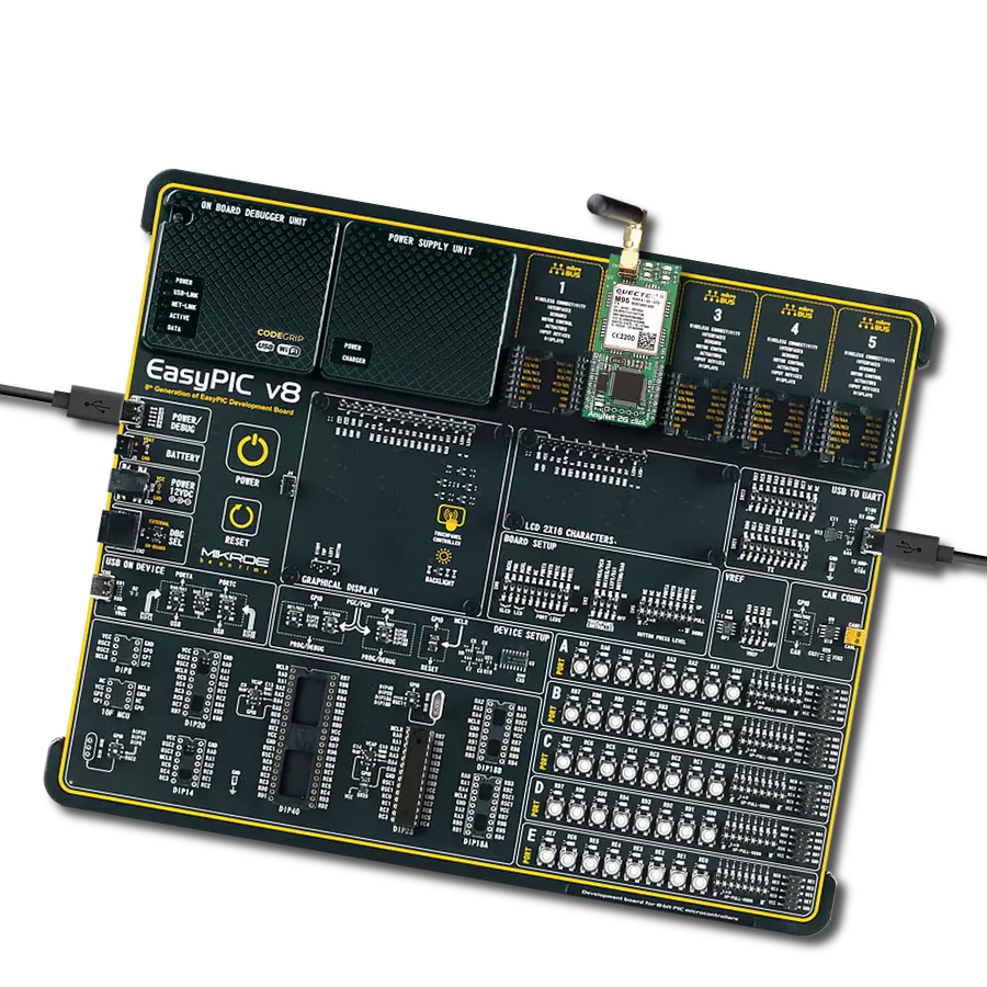
UNI-DS v8 is a development board specially designed for the needs of rapid development of embedded applications. It supports a wide range of microcontrollers, such as different STM32, Kinetis, TIVA, CEC, MSP, PIC, dsPIC, PIC32, and AVR MCUs regardless of their number of pins, and a broad set of unique functions, such as the first-ever embedded debugger/programmer over WiFi. The development board is well organized and designed so that the end-user has all the necessary elements, such as switches, buttons, indicators, connectors, and others, in one place. Thanks to innovative manufacturing technology, UNI-DS v8 provides a fluid and immersive working experience, allowing access anywhere and under any
circumstances at any time. Each part of the UNI-DS v8 development board contains the components necessary for the most efficient operation of the same board. An advanced integrated CODEGRIP programmer/debugger module offers many valuable programming/debugging options, including support for JTAG, SWD, and SWO Trace (Single Wire Output)), and seamless integration with the Mikroe software environment. Besides, it also includes a clean and regulated power supply module for the development board. It can use a wide range of external power sources, including a battery, an external 12V power supply, and a power source via the USB Type-C (USB-C) connector. Communication options such as USB-UART, USB
HOST/DEVICE, CAN (on the MCU card, if supported), and Ethernet is also included. In addition, it also has the well-established mikroBUS™ standard, a standardized socket for the MCU card (SiBRAIN standard), and two display options for the TFT board line of products and character-based LCD. UNI-DS v8 is an integral part of the Mikroe ecosystem for rapid development. Natively supported by Mikroe software tools, it covers many aspects of prototyping and development thanks to a considerable number of different Click boards™ (over a thousand boards), the number of which is growing every day.

Microcontroller Overview
MCU Card / MCU
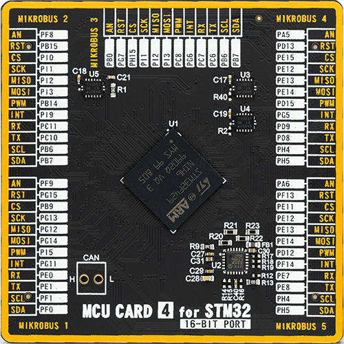
Type
8th Generation
Architecture
ARM Cortex-M4
MCU Memory (KB)
2048
Silicon Vendor
STMicroelectronics
Pin count
216
RAM (Bytes)
262144
You complete me!
Accessories
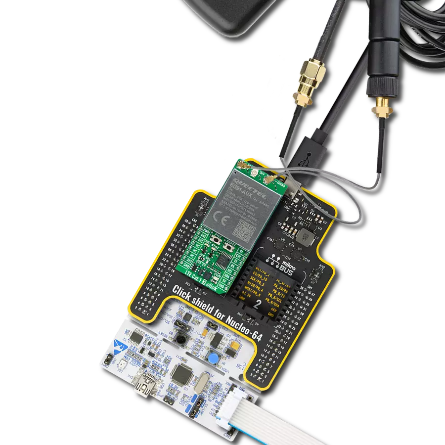
LTE Flat Rotation Antenna is a versatile choice for boosting the performance of 3G/4G LTE devices. With a wide frequency range of 700-2700MHz, it ensures optimal connectivity on major cellular bands worldwide. This flat antenna features an SMA male connector, making it easy to attach directly to your device or SMA module connector. One of its standout features is its adjustable angle, which can be set in 45⁰ increments (0⁰/45⁰/90⁰), allowing you to fine-tune the antenna's orientation for maximum signal reception. With an impedance of 50Ω and a VSW Ratio of <2.0:1, this antenna ensures a reliable and efficient connection. Its 5dB gain, vertical polarization, and omnidirectional radiation pattern enhance signal strength, making it suitable for various applications. Measuring 196mm in length and 38mm in width, this antenna offers a compact yet effective solution for improving your connectivity. With a maximum input power of 50W, it can handle the demands of various devices.

This multiband LTE Rubber Antenna with adjustable angle is an excellent choice for all 3G/4G LTE-based click boards from our offer, as well as other devices that require excellent throughput on all major cellular bands worldwide. The antenna has an SMA male connector, which allows it to be mounted directly on the Click board™ or the female SMA module connector. The antenna position can be adjusted in 45⁰ increments (0⁰/45⁰/90⁰).

Used MCU Pins
mikroBUS™ mapper
Take a closer look
Click board™ Schematic
Step by step
Project assembly

Start by selecting your development board and Click board™. Begin with the UNI-DS v8 as your development board.


Track your results in real time
Application Output
1. Application Output - In Debug mode, the 'Application Output' window enables real-time data monitoring, offering direct insight into execution results. Ensure proper data display by configuring the environment correctly using the provided tutorial.

2. UART Terminal - Use the UART Terminal to monitor data transmission via a USB to UART converter, allowing direct communication between the Click board™ and your development system. Configure the baud rate and other serial settings according to your project's requirements to ensure proper functionality. For step-by-step setup instructions, refer to the provided tutorial.

3. Plot Output - The Plot feature offers a powerful way to visualize real-time sensor data, enabling trend analysis, debugging, and comparison of multiple data points. To set it up correctly, follow the provided tutorial, which includes a step-by-step example of using the Plot feature to display Click board™ readings. To use the Plot feature in your code, use the function: plot(*insert_graph_name*, variable_name);. This is a general format, and it is up to the user to replace 'insert_graph_name' with the actual graph name and 'variable_name' with the parameter to be displayed.

Software Support
Library Description
This library contains API for 4G LTE AT&T Click driver.
Key functions:
c4gltee_module_power_on- TThis function powers ON the modulec4gltee_send_cmd_with_parameter- This function sends a command with specified parameter to the click modulec4gltee_send_cmd_parameter_check- This function checks the command that is sent.
Open Source
Code example
The complete application code and a ready-to-use project are available through the NECTO Studio Package Manager for direct installation in the NECTO Studio. The application code can also be found on the MIKROE GitHub account.
/*!
 * @file main.c
 * @brief 4G LTE-ATT Click Example.
 *
 * # Description
 * This example reads and processes data from 4G LTE-ATT Click.
 *
 * The demo application is composed of two sections :
 *
 * ## Application Init
 * Initializes the driver and powers up the module, then sets default configuration
 * for connecting the device to network.
 *
 * ## Application Task
 * Waits for device to connect to network and then sends a desired SMS to the selected phone number
 * approximately every 30 seconds.
 *
 * ## Additional Function
 * - static void c4glteatt_clear_app_buf ( void )
 * - static void c4glteatt_error_check( err_t error_flag )
 * - static void c4glteatt_log_app_buf ( void )
 * - static void c4glteatt_check_connection( void )
 * - static err_t c4glteatt_rsp_check ( void )
 * - static err_t c4glteatt_process ( void )
 *
 * @note
 * In order for the example to work, user needs to set the phone number to which he wants
 * to send an SMS, and also will need to set an APN and SMSC (required for PDU mode only) of entered SIM card.
 * Enter valid data for the following macros: SIM_APN, SIM_SMSC and PHONE_NUMBER_TO_MESSAGE.
 * E.g.
    SIM_APN "vipmobile"
    SIM_SMSC "+381610401"
    PHONE_NUMBER_TO_MESSAGE "+381659999999"
 *
 * @author Stefan Ilic
 *
 */

#include "board.h"
#include "log.h"
#include "c4glteatt.h"
#include "string.h"

#define APP_OK                              0
#define APP_ERROR_DRIVER                    -1
#define APP_ERROR_OVERFLOW                  -2
#define APP_ERROR_TIMEOUT                   -3

#define RSP_OK                              "OK"
#define RSP_ERROR                           "ERROR"

#define SIM_APN                             ""  // Set valid SIM APN
#define SIM_SMSC                            ""  // Set valid SMS Service Center Address - only in PDU mode
#define PHONE_NUMBER_TO_MESSAGE             ""  // Set Phone number to message
#define MESSAGE_CONTENT                     "4G LTE-ATT Click board - demo example."   // Message content

#define PROCESS_BUFFER_SIZE                 256

#define WAIT_FOR_CONNECTION                 0
#define CONNECTED_TO_NETWORK                1

static c4glteatt_t c4glteatt;
static log_t logger;

static char app_buf[ PROCESS_BUFFER_SIZE ] = { 0 };
static int32_t app_buf_len = 0;
static int32_t app_buf_cnt = 0;

static uint8_t app_connection_status        = WAIT_FOR_CONNECTION;

static err_t app_error_flag;

/**
 * @brief 4G LTE-ATT clearing application buffer.
 * @details This function clears memory of application buffer and reset it's length and counter.
 * @note None.
 */
static void c4glteatt_clear_app_buf ( void );

/**
 * @brief 4G LTE-ATT data reading function.
 * @details This function reads data from device and concatenates data to application buffer.
 *
 * @return @li @c  0 - Read some data.
 *         @li @c -1 - Nothing is read.
 *         @li @c -2 - Application buffer overflow.
 *
 * See #err_t definition for detailed explanation.
 * @note None.
 */
static err_t c4glteatt_process ( void );

/**
 * @brief 4G LTE-ATT check for errors.
 * @details This function checks for different types of errors and logs them on UART.
 * @note None.
 */
static void c4glteatt_error_check( err_t error_flag );

/**
 * @brief 4G LTE-ATT logs application buffer.
 * @details This function logs data from application buffer.
 * @note None.
 */
static void c4glteatt_log_app_buf ( void );

/**
 * @brief 4G LTE-ATT response check.
 * @details This function checks for response and returns the status of response.
 *
 * @return application status.
 * See #err_t definition for detailed explanation.
 * @note None.
 */
static err_t c4glteatt_rsp_check ( void );

/**
 * @brief 4G LTE-ATT check connection.
 * @details This function checks connection to the network and
 *          logs that status to UART.
 *
 * @note None.
 */
static void c4glteatt_check_connection( void );

void application_init ( void ) {
    log_cfg_t log_cfg;  /**< Logger config object. */
    c4glteatt_cfg_t c4glteatt_cfg;  /**< Click config object. */

    /**
     * Logger initialization.
     * Default baud rate: 115200
     * Default log level: LOG_LEVEL_DEBUG
     * @note If USB_UART_RX and USB_UART_TX
     * are defined as HAL_PIN_NC, you will
     * need to define them manually for log to work.
     * See @b LOG_MAP_USB_UART macro definition for detailed explanation.
     */
    LOG_MAP_USB_UART( log_cfg );
    log_init( &logger, &log_cfg );
    log_info( &logger, " Application Init " );

    // Click initialization.

    c4glteatt_cfg_setup( &c4glteatt_cfg );
    C4GLTEATT_MAP_MIKROBUS( c4glteatt_cfg, MIKROBUS_1 );
    c4glteatt_init( &c4glteatt, &c4glteatt_cfg );

    c4glteatt_module_power_on( &c4glteatt );

    // dummy read
    c4glteatt_process( );
    c4glteatt_clear_app_buf( );

    // AT
    c4glteatt_send_cmd( &c4glteatt, C4GLTEATT_CMD_AT );
    app_error_flag = c4glteatt_rsp_check( );
    c4glteatt_error_check( app_error_flag );
    Delay_ms ( 500 );

    // ATI - product information
    c4glteatt_send_cmd( &c4glteatt, C4GLTEATT_CMD_ATI );
    app_error_flag = c4glteatt_rsp_check(  );
    c4glteatt_error_check( app_error_flag );
    Delay_ms ( 500 );

    // CGMR - firmware version
    c4glteatt_send_cmd( &c4glteatt, C4GLTEATT_CMD_CGMR );
    app_error_flag = c4glteatt_rsp_check(  );
    c4glteatt_error_check( app_error_flag );
    Delay_ms ( 500 );

    // CMEE - Report Mobile Equipment Error
    c4glteatt_send_cmd_with_parameter( &c4glteatt, C4GLTEATT_CMD_CMEE, "2" );
    app_error_flag = c4glteatt_rsp_check(  );
    c4glteatt_error_check( app_error_flag );
    Delay_ms ( 500 );

    // COPS - deregister from network
    c4glteatt_send_cmd_with_parameter( &c4glteatt, C4GLTEATT_CMD_COPS, "2" );
    Delay_ms ( 1000 );
    Delay_ms ( 1000 );
    Delay_ms ( 1000 );
    Delay_ms ( 1000 );
    app_error_flag = c4glteatt_rsp_check(  );
    c4glteatt_error_check( app_error_flag );
    Delay_ms ( 500 );

    // CGDCONT - set sim apn
    c4glteatt_set_sim_apn( &c4glteatt, SIM_APN );
    app_error_flag = c4glteatt_rsp_check(  );
    c4glteatt_error_check( app_error_flag );
    Delay_ms ( 500 );

    // CFUN - full funtionality
    c4glteatt_send_cmd_with_parameter( &c4glteatt, C4GLTEATT_CMD_CFUN, "1" );
    Delay_ms ( 1000 );
    Delay_ms ( 1000 );
    app_error_flag = c4glteatt_rsp_check(  );
    c4glteatt_error_check( app_error_flag );
    Delay_ms ( 500 );

    // COPS - automatic mode
    c4glteatt_send_cmd_with_parameter( &c4glteatt, C4GLTEATT_CMD_COPS, "0" );
    Delay_ms ( 1000 );
    Delay_ms ( 1000 );
    Delay_ms ( 1000 );
    Delay_ms ( 1000 );
    app_error_flag = c4glteatt_rsp_check(  );
    c4glteatt_error_check( app_error_flag );
    Delay_ms ( 500 );

    // CREG - network registration status
    c4glteatt_send_cmd_with_parameter( &c4glteatt, C4GLTEATT_CMD_CREG, "1" );
    app_error_flag = c4glteatt_rsp_check(  );
    c4glteatt_error_check( app_error_flag );
    Delay_ms ( 500 );

    app_buf_len = 0;
    app_buf_cnt = 0;
    app_connection_status = WAIT_FOR_CONNECTION;
    log_info( &logger, " Application Task " );
    Delay_ms ( 1000 );
    Delay_ms ( 1000 );
    Delay_ms ( 1000 );
    Delay_ms ( 1000 );
    Delay_ms ( 1000 );
}

void application_task ( void ) {
    if ( app_connection_status == WAIT_FOR_CONNECTION ) {
        // CREG - network registration status
        c4glteatt_send_cmd_check( &c4glteatt, C4GLTEATT_CMD_CREG );
        app_error_flag = c4glteatt_rsp_check(  );
        c4glteatt_error_check( app_error_flag );
        Delay_ms ( 500 );

        // CSQ - signal quality
        c4glteatt_send_cmd( &c4glteatt, C4GLTEATT_CMD_CSQ );
        app_error_flag = c4glteatt_rsp_check(  );
        c4glteatt_error_check( app_error_flag );
        Delay_ms ( 1000 );
        Delay_ms ( 1000 );
        Delay_ms ( 1000 );
    } else {
        log_info( &logger, "CONNECTED TO NETWORK" );

        // SMS message format - PDU mode
        c4glteatt_send_cmd_with_parameter( &c4glteatt, C4GLTEATT_CMD_CMGF, "0" );
        app_error_flag = c4glteatt_rsp_check(  );
        c4glteatt_error_check( app_error_flag );
        Delay_ms ( 1000 );
        Delay_ms ( 1000 );
        Delay_ms ( 1000 );

        for( ; ; ) {
            log_printf( &logger, "> Sending message to phone number...\r\n" );
            c4glteatt_send_sms_pdu ( &c4glteatt, SIM_SMSC, PHONE_NUMBER_TO_MESSAGE, MESSAGE_CONTENT );
            app_error_flag = c4glteatt_rsp_check(  );
            c4glteatt_error_check( app_error_flag );
            // 30 seconds delay
            Delay_ms ( 1000 );
            Delay_ms ( 1000 );
            Delay_ms ( 1000 );
            Delay_ms ( 1000 );
            Delay_ms ( 1000 );
            Delay_ms ( 1000 );
            Delay_ms ( 1000 );
            Delay_ms ( 1000 );
            Delay_ms ( 1000 );
            Delay_ms ( 1000 );
            Delay_ms ( 1000 );
            Delay_ms ( 1000 );
            Delay_ms ( 1000 );
            Delay_ms ( 1000 );
            Delay_ms ( 1000 );
            Delay_ms ( 1000 );
            Delay_ms ( 1000 );
            Delay_ms ( 1000 );
            Delay_ms ( 1000 );
            Delay_ms ( 1000 );
            Delay_ms ( 1000 );
            Delay_ms ( 1000 );
            Delay_ms ( 1000 );
            Delay_ms ( 1000 );
            Delay_ms ( 1000 );
            Delay_ms ( 1000 );
            Delay_ms ( 1000 );
            Delay_ms ( 1000 );
            Delay_ms ( 1000 );
            Delay_ms ( 1000 );
        }
    }
}

int main ( void )
{
    /* Do not remove this line or clock might not be set correctly. */
    #ifdef PREINIT_SUPPORTED
    preinit();
    #endif

    application_init( );

    for ( ; ; )
    {
        application_task( );
    }

    return 0;
}

static void c4glteatt_clear_app_buf ( void ) {
    memset( app_buf, 0, app_buf_len );
    app_buf_len = 0;
    app_buf_cnt = 0;
}

static err_t c4glteatt_process ( void ) {
    err_t return_flag = APP_ERROR_DRIVER;
    int32_t rx_size;
    char rx_buff[ PROCESS_BUFFER_SIZE ] = { 0 };

    rx_size = c4glteatt_generic_read( &c4glteatt, rx_buff, PROCESS_BUFFER_SIZE );

    if ( rx_size > 0 ) {
        int32_t buf_cnt = 0;
        return_flag = APP_OK;

        if ( app_buf_len + rx_size >= PROCESS_BUFFER_SIZE ) {
            c4glteatt_clear_app_buf(  );
            return_flag = APP_ERROR_OVERFLOW;
        } else {
            buf_cnt = app_buf_len;
            app_buf_len += rx_size;
        }

        for ( int32_t rx_cnt = 0; rx_cnt < rx_size; rx_cnt++ ) {
            if ( rx_buff[ rx_cnt ] != 0 ) {
                app_buf[ ( buf_cnt + rx_cnt ) ] = rx_buff[ rx_cnt ];
            } else {
                app_buf_len--;
                buf_cnt--;
            }
        }
    }

    return return_flag;
}

static err_t c4glteatt_rsp_check ( void ) {
    uint16_t timeout_cnt = 0;
    uint32_t timeout = 100000;

    err_t error_flag = c4glteatt_process(  );

    if ( ( error_flag != 0 ) && ( error_flag != -1 ) ) {
        return error_flag;
    }

    while ( ( strstr( app_buf, RSP_OK ) == 0 ) && ( strstr( app_buf, RSP_ERROR ) == 0 ) ) {
        error_flag = c4glteatt_process(  );
        if ( ( error_flag != 0 ) && ( error_flag != -1 ) ) {
            return error_flag;
        }

        timeout_cnt++;
        if ( timeout_cnt > timeout ) {
            while ( ( strstr( app_buf, RSP_OK ) == 0 ) && ( strstr( app_buf, RSP_ERROR ) == 0 ) ) {
                c4glteatt_send_cmd( &c4glteatt, C4GLTEATT_CMD_AT );
                c4glteatt_process(  );
                Delay_ms ( 100 );
            }
            c4glteatt_clear_app_buf(  );
            return APP_ERROR_TIMEOUT;
        }

        Delay_ms ( 1 );
    }

    c4glteatt_check_connection();

    c4glteatt_log_app_buf();

    return APP_OK;
}

static void c4glteatt_error_check( err_t error_flag ) {
    if ( ( error_flag != 0 ) && ( error_flag != -1 ) ) {
        switch ( error_flag ) {
            case -2: {
                log_error( &logger, " Overflow!" );
                break;
            }
            case -3: {
                log_error( &logger, " Timeout!" );
                break;
            }
            default: {
                break;
            }
        }
    }
}

static void c4glteatt_log_app_buf ( void ) {
    for ( int32_t buf_cnt = 0; buf_cnt < app_buf_len; buf_cnt++ ) {
        log_printf( &logger, "%c", app_buf[ buf_cnt ] );
    }
    log_printf( &logger, "\r\n-----------------------------------\r\n" );

    c4glteatt_clear_app_buf(  );
}

static void c4glteatt_check_connection( void ) {
    #define CONNECTED "+CREG: 1,1"

    if ( strstr( app_buf, CONNECTED ) != 0 ) {
        app_connection_status = CONNECTED_TO_NETWORK;
    }
}


// ------------------------------------------------------------------------ END