Experience the freedom to connect and control an array of I2C devices with PI4MSD5V9547 and TM4C129ENCPDT
Multiplexing marvel: I2C device management perfected!
Published Sep 04, 2023
Click board™
I2C MUX 7 Click
Dev. board
Fusion for Tiva v8
Compiler
NECTO Studio
MCU
TM4C129ENCPDT
Effortlessly manage your I2C device network with our multiplexer solution, making it an essential tool for engineers and developers seeking efficient and reliable communication in their projects
A
A
Hardware Overview
How does it work?
I2C MUX 7 Click is based on the PI4MSD5V9547, a low voltage octal bidirectional translating multiplexer with an active-low reset input controlled through the I2C serial interface from Texas Instruments. The host SCL/SDA signal pair is directed to eight channels CH0-CH7, where only one SCL/SDA channel can be selected at a time, determined by the contents of the programmable control register. The board powers up with Channel 0 connected, allowing immediate communication between the Host and downstream devices on that channel. This Click board™ includes a low dropout linear regulator AP2112 from Diodes Incorporated to provide the 1.8V supply voltage for the PI4MSD5V9547. When power is applied to the IC, an internal Power-On
Reset (POR) holds the PI4MSD5V9547 in a reset condition until the power supply reaches the POR voltage level. At this point, the reset condition is released, and the PI4MSD5V9547 registers and I2C-bus state machine are initialized to their default states (all zeroes), causing deselection of all channels. I2C MUX 7 Click communicates with MCU using the standard I2C 2-Wire interface that supports Standard-Mode (100 kHz) and Fast-Mode (400 kHz) operations. The PI4MSD5V9547 has a 7-bit slave address with the first five MSBs fixed to 1110. The address pins A0, A1, and A2 are programmed by the user and determine the value of the last three LSBs of the slave address, which can be selected by onboard SMD jumpers labeled as ADDR SEL, allowing selection of the slave
address LSBs. Alongside the internal Power-On Reset (POR) function, this board also has an active-low reset signal routed on the RST pin of the mikroBUS™ socket used to recover from a bus-fault condition. When this signal is asserted low, the PI4MSD5V9547 resets its registers alongside the I2C state machine and deselects all channels. This Click board™ can operate with either 3.3V or 5V logic voltage levels selected via the VCC SEL jumper. This way, both 3.3V and 5V capable MCUs can use the communication lines properly. Also, this Click board™ comes equipped with a library containing easy-to-use functions and an example code that can be used as a reference for further development.


Features overview
Development board
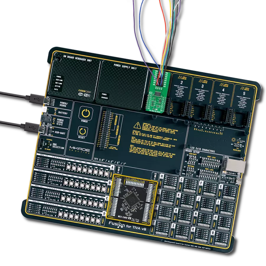
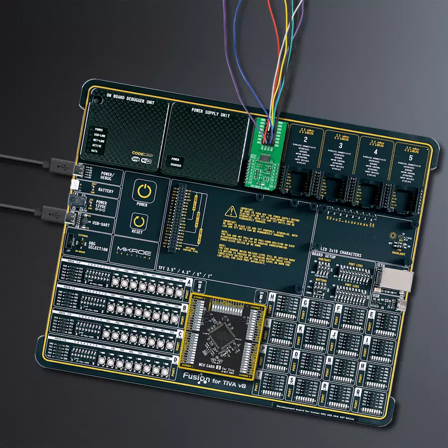
Fusion for TIVA v8 is a development board specially designed for the needs of rapid development of embedded applications. It supports a wide range of microcontrollers, such as different 32-bit ARM® Cortex®-M based MCUs from Texas Instruments, regardless of their number of pins, and a broad set of unique functions, such as the first-ever embedded debugger/programmer over a WiFi network. The development board is well organized and designed so that the end-user has all the necessary elements, such as switches, buttons, indicators, connectors, and others, in one place. Thanks to innovative manufacturing technology, Fusion for TIVA v8 provides a fluid and immersive working experience, allowing access
anywhere and under any circumstances at any time. Each part of the Fusion for TIVA v8 development board contains the components necessary for the most efficient operation of the same board. An advanced integrated CODEGRIP programmer/debugger module offers many valuable programming/debugging options, including support for JTAG, SWD, and SWO Trace (Single Wire Output)), and seamless integration with the Mikroe software environment. Besides, it also includes a clean and regulated power supply module for the development board. It can use a wide range of external power sources, including a battery, an external 12V power supply, and a power source via the USB Type-C (USB-C) connector.
Communication options such as USB-UART, USB HOST/DEVICE, CAN (on the MCU card, if supported), and Ethernet is also included. In addition, it also has the well-established mikroBUS™ standard, a standardized socket for the MCU card (SiBRAIN standard), and two display options for the TFT board line of products and character-based LCD. Fusion for TIVA v8 is an integral part of the Mikroe ecosystem for rapid development. Natively supported by Mikroe software tools, it covers many aspects of prototyping and development thanks to a considerable number of different Click boards™ (over a thousand boards), the number of which is growing every day.

Microcontroller Overview
MCU Card / MCU

Type
8th Generation
Architecture
ARM Cortex-M4
MCU Memory (KB)
1024
Silicon Vendor
Texas Instruments
Pin count
128
RAM (Bytes)
262144
Used MCU Pins
mikroBUS™ mapper
Take a closer look
Click board™ Schematic

Step by step
Project assembly

Start by selecting your development board and Click board™. Begin with the Fusion for Tiva v8 as your development board.


Software Support
Library Description
This library contains API for I2C MUX 7 Click driver.
Key functions:
i2cmux7_set_channel- This function sets the desired channel active and configures its slave addressi2cmux7_read_channel- This function reads the currently selected channel valuei2cmux7_generic_read- This function reads a desired number of data bytes starting from the selected register by using I2C serial interface
Open Source
Code example
The complete application code and a ready-to-use project are available through the NECTO Studio Package Manager for direct installation in the NECTO Studio. The application code can also be found on the MIKROE GitHub account.
/*!
 * @file main.c
 * @brief I2CMUX7 Click example
 *
 * # Description
 * This example demonstrates the use of I2C MUX 7 Click board by reading the
 * device ID of a 6DOF IMU 11 and Compass 3 Click boards connected to
 * the channels 0 and 7 respectfully.
 *
 * The demo application is composed of two sections :
 *
 * ## Application Init
 * Initializes the driver and resets the device.
 *
 * ## Application Task
 * Reads the device ID of the connected Click boards.
 * Channel 0 : 6DOF IMU 11 Click [slave address: 0x0E; reg: 0x00; id: 0x2D],
 * Channel 7 : Compass 3 Click   [slave address: 0x30; reg: 0x2F; id: 0x0C].
 * All data is being logged on the USB UART where you can check the device ID.
 *
 * @author Stefan Filipovic
 *
 */

#include "board.h"
#include "log.h"
#include "i2cmux7.h"

#define DEVICE0_NAME                "6DOF IMU 11 Click"
#define DEVICE0_POSITION            I2CMUX7_CHANNEL_0
#define DEVICE0_SLAVE_ADDRESS       0x0E
#define DEVICE0_REG_ID              0x00
#define DEVICE0_ID                  0x2D

#define DEVICE1_NAME                "Compass 3 Click"
#define DEVICE1_POSITION            I2CMUX7_CHANNEL_7
#define DEVICE1_SLAVE_ADDRESS       0x30
#define DEVICE1_REG_ID              0x2F
#define DEVICE1_ID                  0x0C

static i2cmux7_t i2cmux7;
static log_t logger;

void application_init ( void )
{
    log_cfg_t log_cfg;  /**< Logger config object. */
    i2cmux7_cfg_t i2cmux7_cfg;  /**< Click config object. */

    /**
     * Logger initialization.
     * Default baud rate: 115200
     * Default log level: LOG_LEVEL_DEBUG
     * @note If USB_UART_RX and USB_UART_TX
     * are defined as HAL_PIN_NC, you will
     * need to define them manually for log to work.
     * See @b LOG_MAP_USB_UART macro definition for detailed explanation.
     */
    LOG_MAP_USB_UART( log_cfg );
    log_init( &logger, &log_cfg );
    log_info( &logger, " Application Init " );

    // Click initialization.
    i2cmux7_cfg_setup( &i2cmux7_cfg );
    I2CMUX7_MAP_MIKROBUS( i2cmux7_cfg, MIKROBUS_1 );
    if ( I2C_MASTER_ERROR == i2cmux7_init( &i2cmux7, &i2cmux7_cfg ) )
    {
        log_error( &logger, " Communication init." );
        for ( ; ; );
    }

    i2cmux7_reset_device ( &i2cmux7 );

    log_info( &logger, " Application Task " );
}

void application_task ( void )
{
    uint8_t channel, device_id;
    if ( I2CMUX7_OK == i2cmux7_set_channel ( &i2cmux7, DEVICE0_POSITION, DEVICE0_SLAVE_ADDRESS ) )
    {
        if ( I2CMUX7_OK == i2cmux7_read_channel ( &i2cmux7, &channel ) )
        {
            log_printf( &logger, " --- Channel %u --- \r\n", ( uint16_t ) ( channel & I2CMUX7_CHANNEL_NUM_MASK ) );
        }
        if ( I2CMUX7_OK == i2cmux7_generic_read ( &i2cmux7, DEVICE0_REG_ID, &device_id, 1 ) )
        {
            log_printf( &logger, " %s - Device ID: 0x%.2X \r\n\n", ( char * ) DEVICE0_NAME, ( uint16_t ) device_id );
        }
        Delay_ms ( 1000 );
    }
    if ( I2CMUX7_OK == i2cmux7_set_channel ( &i2cmux7, DEVICE1_POSITION, DEVICE1_SLAVE_ADDRESS ) )
    {
        if ( I2CMUX7_OK == i2cmux7_read_channel ( &i2cmux7, &channel ) )
        {
            log_printf( &logger, " --- Channel %u --- \r\n", ( uint16_t ) ( channel & I2CMUX7_CHANNEL_NUM_MASK ) );
        }
        if ( I2CMUX7_OK == i2cmux7_generic_read ( &i2cmux7, DEVICE1_REG_ID, &device_id, 1 ) )
        {
            log_printf( &logger, " %s - Device ID: 0x%.2X \r\n\n", ( char * ) DEVICE1_NAME, ( uint16_t ) device_id );
        }
        Delay_ms ( 1000 );
    }
}

int main ( void )
{
    /* Do not remove this line or clock might not be set correctly. */
    #ifdef PREINIT_SUPPORTED
    preinit();
    #endif

    application_init( );

    for ( ; ; )
    {
        application_task( );
    }

    return 0;
}

// ------------------------------------------------------------------------ END
Additional Support
Resources
Category:I2C


