Create breathtaking graphics and animations with PSP27801 and STM32F302VC
Color your world
Published Jul 22, 2025
Click board™
OLED C Click
Dev. board
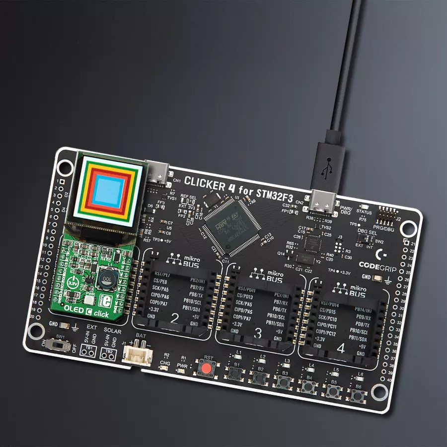
CLICKER 4 for STM32F302VCT6
Compiler
NECTO Studio
MCU
STM32F302VC
Dive into the world of vibrant visuals and immersive experiences as we showcase how this OLED display solution can transform your product design and captivate your audience.
A
A
Hardware Overview
How does it work?
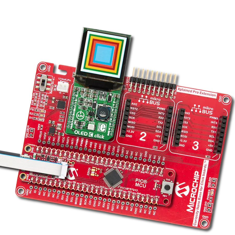
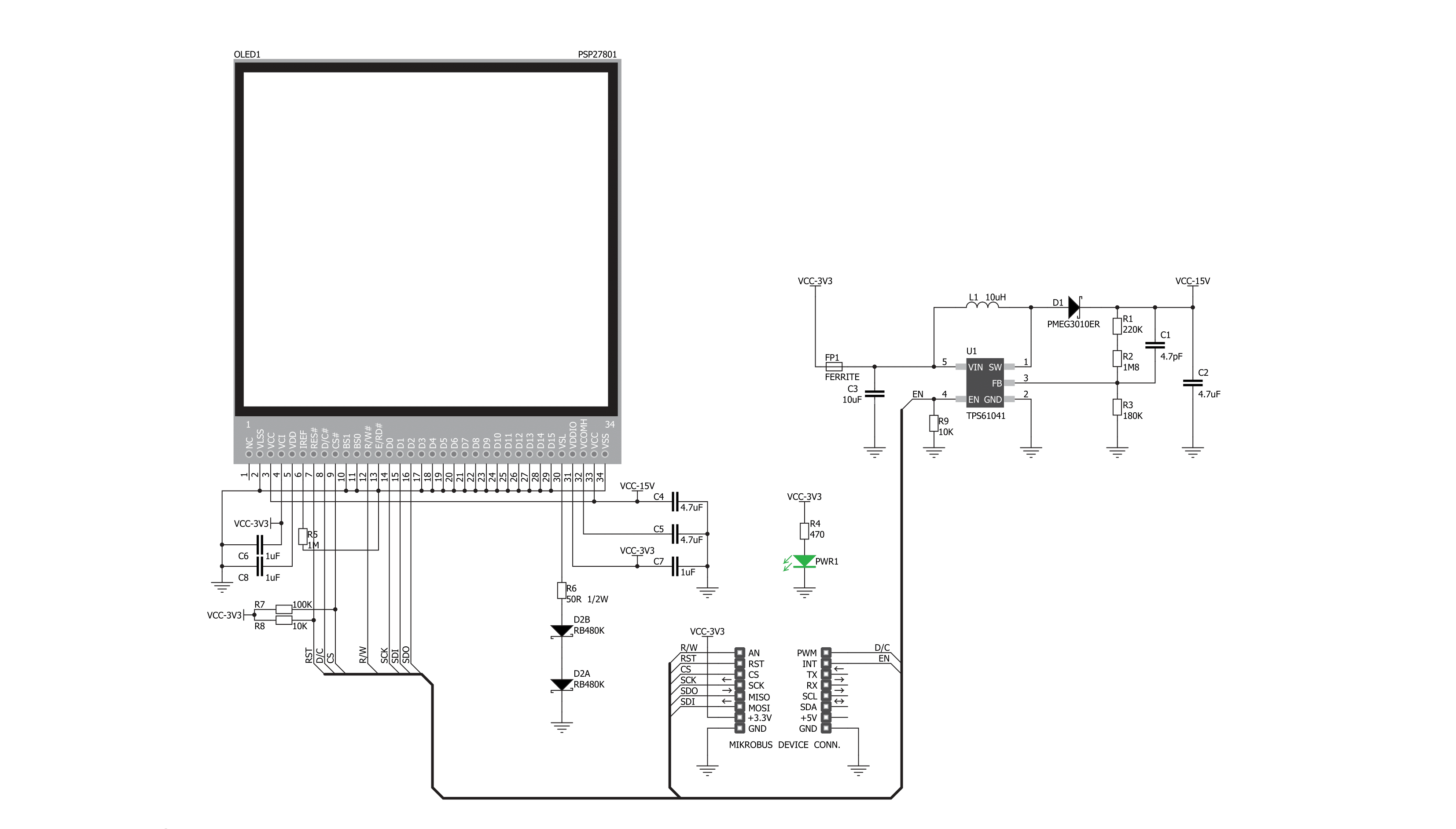
OLED C Click is based on the PSP27801, a 25x25mm 96x96px full-color square OLED display from Shenzhen Boxing World Technology. The graphics driver used on this OLED display is the SSD1351, the display driver IC from Solomon Systech. The graphics driver comes with the embedded 128x128x18-bit SRAM display buffer. It is designed to work with a common cathode type of OLED display and has both parallel (8080/6800) and serial interfaces for communication. The SSD1351 controller also has built-in functionalities like vertical and horizontal scrolling, programmable frame rate, row and column remapping, and color swapping, and supports two color modes: 65K (6:5:6) and 262K (6:6:6). The OLED
C Click uses a standard 4-Wire SPI serial interface or parallel to communicate with the host MCU. It also occupies several other pins of the mikroBUS™ socket, such as the RST pin for resetting the OLED display, and the R/W pin of the mikroBUS™ socket is used only for parallel communication, which should be pulled to a LOW logic state when using serial communication as is the case here. The D/C is a data/command pin and is in a tight connection with the CS pin, as when the CS is at the LOW logic level, the display expects data or command. In addition to the display's main power supply, taken from the 3.3V mikroBUS™ power rail, the PSP27801 has another power pin, more precisely, the power supply for its DC/DC
converter circuit. For that reason, this Click board™ uses a low-power onboard step-up converter TPS61041, which can be turned ON or OFF through the EN pin of the mikroBUS™ socket, providing a 15V power supply out of 3.3V mikroBUS™ rail. The EN pin turns the step-up converter ON or OFF and, consequently - the OLED screen itself. This Click board™ can be operated only with a 3.3V logic voltage level. The board must perform appropriate logic voltage level conversion before using MCUs with different logic levels. Also, it comes equipped with a library containing functions and an example code that can be used as a reference for further development.


Features overview
Development board
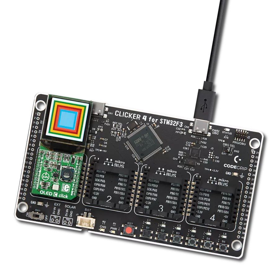
Clicker 4 for STM32F3 is a compact development board designed as a complete solution, you can use it to quickly build your own gadgets with unique functionalities. Featuring a STM32F302VCT6, four mikroBUS™ sockets for Click boards™ connectivity, power managment, and more, it represents a perfect solution for the rapid development of many different types of applications. At its core, there is a STM32F302VCT6 MCU, a powerful microcontroller by STMicroelectronics, based on the high-
performance Arm® Cortex®-M4 32-bit processor core operating at up to 168 MHz frequency. It provides sufficient processing power for the most demanding tasks, allowing Clicker 4 to adapt to any specific application requirements. Besides two 1x20 pin headers, four improved mikroBUS™ sockets represent the most distinctive connectivity feature, allowing access to a huge base of Click boards™, growing on a daily basis. Each section of Clicker 4 is clearly marked, offering an intuitive and clean interface. This makes working with the development
board much simpler and thus, faster. The usability of Clicker 4 doesn’t end with its ability to accelerate the prototyping and application development stages: it is designed as a complete solution which can be implemented directly into any project, with no additional hardware modifications required. Four mounting holes [4.2mm/0.165”] at all four corners allow simple installation by using mounting screws. For most applications, a nice stylish casing is all that is needed to turn the Clicker 4 development board into a fully functional, custom design.

Microcontroller Overview
MCU Card / MCU

Architecture
ARM Cortex-M4
MCU Memory (KB)
256
Silicon Vendor
STMicroelectronics
Pin count
100
RAM (Bytes)
40960
Used MCU Pins
mikroBUS™ mapper
Take a closer look
Click board™ Schematic
Step by step
Project assembly

Start by selecting your development board and Click board™. Begin with the CLICKER 4 for STM32F302VCT6 as your development board.


Track your results in real time
Application Output
1. Application Output - In Debug mode, the 'Application Output' window enables real-time data monitoring, offering direct insight into execution results. Ensure proper data display by configuring the environment correctly using the provided tutorial.

2. UART Terminal - Use the UART Terminal to monitor data transmission via a USB to UART converter, allowing direct communication between the Click board™ and your development system. Configure the baud rate and other serial settings according to your project's requirements to ensure proper functionality. For step-by-step setup instructions, refer to the provided tutorial.

3. Plot Output - The Plot feature offers a powerful way to visualize real-time sensor data, enabling trend analysis, debugging, and comparison of multiple data points. To set it up correctly, follow the provided tutorial, which includes a step-by-step example of using the Plot feature to display Click board™ readings. To use the Plot feature in your code, use the function: plot(*insert_graph_name*, variable_name);. This is a general format, and it is up to the user to replace 'insert_graph_name' with the actual graph name and 'variable_name' with the parameter to be displayed.

Software Support
Library Description
This library contains API for OLED C Click driver.
Key functions:
oledc_fill_screen- Fill Screenoledc_image- Draw BMP Image
Open Source
Code example
The complete application code and a ready-to-use project are available through the NECTO Studio Package Manager for direct installation in the NECTO Studio. The application code can also be found on the MIKROE GitHub account.
/*!
 * \file
 * \brief OledC Click example
 *
 * # Description
 * This demo demonstrates the use of the OLED C Click board and the control of
 * the OLED C display.
 *
 * The demo application is composed of two sections :
 *
 * ## Application Init
 * Initializes driver init and OLED C init and sets full screen on white color
 * with writting demo text.
 *
 * ## Application Task
 * This function is composed of three sections :
 *  -  Display demo rectangle.
 *  -  Display demo line.
 *  -  Display demo image.
 *
 * \author MikroE Team
 *
 */
// ------------------------------------------------------------------- INCLUDES

#include "board.h"
#include "log.h"
#include "oledc.h"
#include "oledc_image.h"
#ifndef IMAGE_MODE_ONLY
#include "oledc_font.h"
#endif

// ------------------------------------------------------------------ VARIABLES

static oledc_t oledc;
static log_t logger;

#define text1 "Hello"
#define text2  "this is the demo"
#define text3  "for OLED C Click"

// ------------------------------------------------------ APPLICATION FUNCTIONS

void application_init ( void )
{
    log_cfg_t log_cfg;
    oledc_cfg_t cfg;

    /**
     * Logger initialization.
     * Default baud rate: 115200
     * Default log level: LOG_LEVEL_DEBUG
     * @note If USB_UART_RX and USB_UART_TX
     * are defined as HAL_PIN_NC, you will
     * need to define them manually for log to work.
     * See @b LOG_MAP_USB_UART macro definition for detailed explanation.
     */
    LOG_MAP_USB_UART( log_cfg );
    log_init( &logger, &log_cfg );
    log_info( &logger, "---- Application Init ----" );

    //  Click initialization.

    oledc_cfg_setup( &cfg );
    OLEDC_MAP_MIKROBUS( cfg, MIKROBUS_1 );
    oledc_init( &oledc, &cfg );

    oledc_default_cfg( &oledc );
    oledc_fill_screen( &oledc, 0xFFFF );

#ifndef IMAGE_MODE_ONLY
    oledc_set_font( &oledc, guiFont_Tahoma_8_Regular, 0 );
    oledc_text( &oledc, text1, 15, 10 );
    oledc_text( &oledc, text2, 5, 30 );
    oledc_text( &oledc, text3, 5, 45 );
#endif
    Delay_ms ( 1000 );
}

void application_task ( void )
{
    oledc_fill_screen( &oledc, 0xFFFF );
    Delay_100ms();

    // Rectangle demo
    oledc_rectangle( &oledc, 0, 0, 96, 96, 0xF000 );
    Delay_ms ( 500 );
    oledc_rectangle( &oledc, 5, 5, 91, 91, 0xFF00 );
    Delay_ms ( 500 );
    oledc_rectangle( &oledc, 10, 10, 86, 86, 0x00F0 );
    Delay_ms ( 500 );
    oledc_rectangle( &oledc, 15, 15, 81, 81, 0x0F0F );
    Delay_ms ( 500 );
    oledc_rectangle( &oledc, 20, 20, 76, 76, 0xF000 );
    Delay_ms ( 500 );
    oledc_rectangle( &oledc, 25, 25, 71, 71, 0xFF00 );
    Delay_100ms();

    // Line demo
    oledc_rectangle( &oledc, 25, 25, 71, 27, 0 );
    Delay_100ms();
    oledc_rectangle( &oledc, 25, 71, 71, 73, 0 );
    Delay_100ms();
    oledc_rectangle( &oledc, 25, 25, 27, 71, 0 );
    Delay_100ms();
    oledc_rectangle( &oledc, 68, 25, 71, 71, 0 );
    Delay_ms ( 1000 );
    Delay_ms ( 1000 );
    Delay_ms ( 1000 );


    // Image demo
    oledc_image( &oledc, mikroe_with_slogan96x96, 0, 0 );
    Delay_ms ( 1000 );
    Delay_ms ( 1000 );
}

int main ( void )
{
    /* Do not remove this line or clock might not be set correctly. */
    #ifdef PREINIT_SUPPORTED
    preinit();
    #endif

    application_init( );

    for ( ; ; )
    {
        application_task( );
    }

    return 0;
}


// ------------------------------------------------------------------------ END
Additional Support
Resources
Category:OLED