Enable secure and reliable long-range data transmission with RAK3172 and TM4C123GH6PZ
Class A/B/C LoRaWAN 1.0.3 low-power solution for wireless communication in IoT networks

Published Nov 14, 2024
Click board™
LR 14 Click
Dev. board
Fusion for Tiva v8
Compiler
NECTO Studio
MCU
TM4C123GH6PZ
Achieve long-range, low-power wireless communication for IoT networks with LoRaWAN support perfect for remote sensing, asset tracking, and IoT deployments
A
A
Hardware Overview
How does it work?
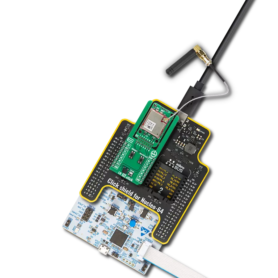
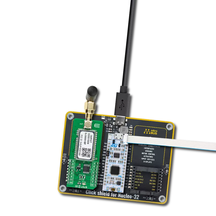
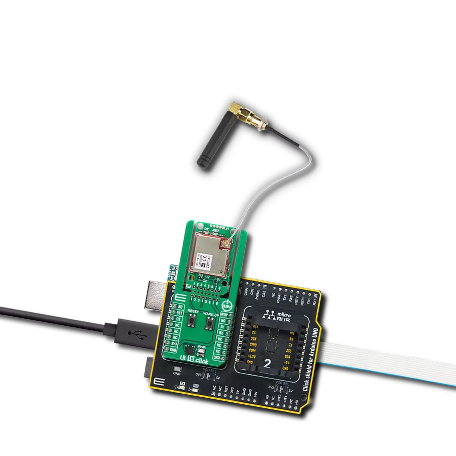
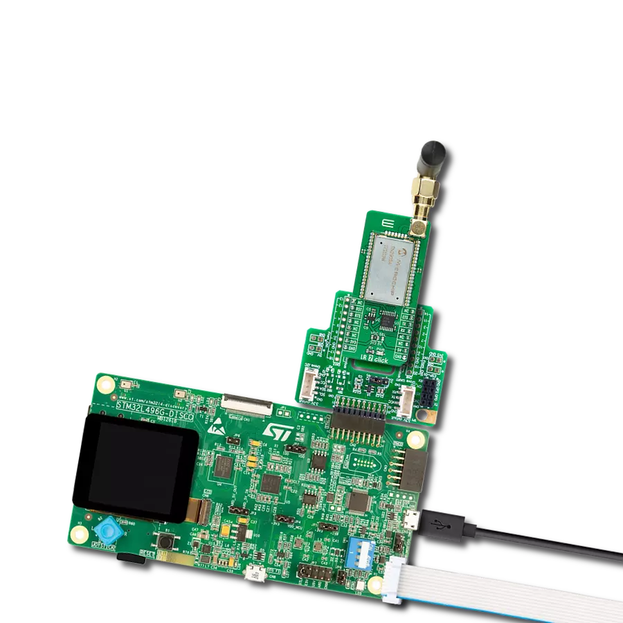
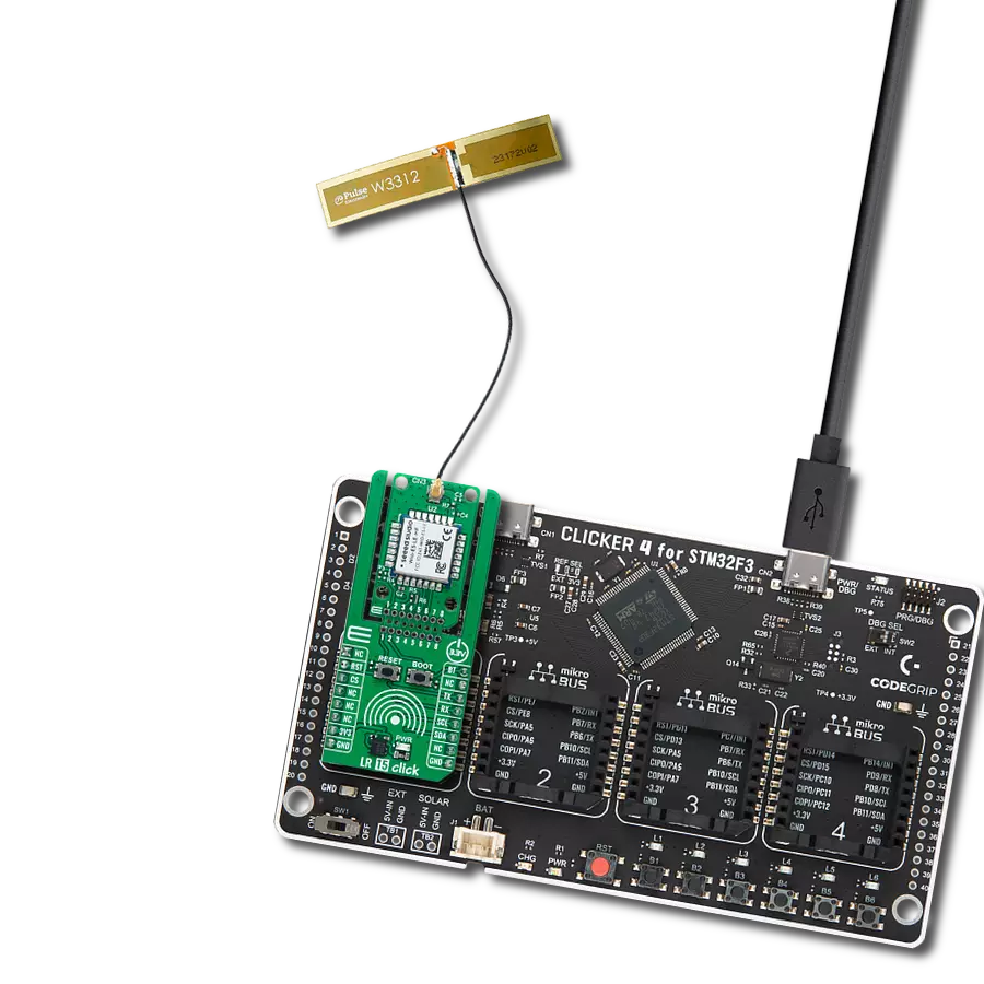
LR 14 Click is based on the RAK3172, Class A/B/C LoRaWAN 1.0.3 low-power module from RAKwireless Technology. This module incorporates the STM32WLE5CC, an ARM Cortex-M4 32-bit chip, and is designed for low-power, long-range data transmission in wireless applications, ideal for IoT networks. The RAK3172 module in LR 14 Click allows easy integration with LoRaWAN server platforms such as TheThingsNetwork (TTN), Chirpstack, and Actility, facilitating a broad range of LoRaWAN applications. It also supports LoRa Point-to-Point (P2P) communication, enabling users to set up custom LoRa networks quickly and effectively without relying on external servers. Compatible with multiple frequency bands — including IN865, EU868, and RU864 — the RAK3172 module provides significant flexibility, achieving communication distances of over 15km when paired with an optimized antenna. Operating the module is straightforward, as the RAK3172 can be configured using AT commands sent through a UART interface, providing an intuitive control scheme for fine-tuning modes and operational parameters. This versatility and its low-power capabilities make LR 14 Click particularly suited to battery-powered applications, where efficient energy consumption is essential. Additionally, LR
14 Click includes both SPI and I2C interfaces to expand its functionality. The SPI interface is dedicated to interacting with the RF subsystem of the STM32WLE5CCU6, enabling robust management of the module's wireless communication capabilities. Meanwhile, the I2C interface allows the board to function as a host, leveraging its internal MCU to control external I2C peripheral devices. The Click board™ also includes a USB Type-C connector, allowing both power supply and configuration via a PC. This functionality is enabled by the CP2102N, a highly integrated USB-to-UART bridge, along with the NCP186 LDO regulator, which converts the USB supply to the necessary 3.3V for the module. Additionally, the board can operate as a fully standalone unit with a battery connected through its dedicated battery connector. This battery is rechargeable by the MC34671 battery charger. The orange CHG LED visually indicates the charging process, providing real-time status feedback. In addition to the interface pins, this board includes extra mikroBUS™ pins for enhanced control. The RST pin and a dedicated RST button allow for easy module resetting, while the AN pin enables monitoring of the connected battery's status. LR 14 Click incorporates several additional features that
enhance its functionality and adaptability. A 6-pin SWD connector enables firmware updates for the RAK3172 module, ensuring users can easily keep the module up to date. The BOOT button provides control over the bootloader; pressing it initiates the bootloader for firmware updates via UART, and releasing it exits the bootloader, returning control to the main application firmware. For power optimization, specific traces on the back of the board can be cut to disable components like LED indicators and battery voltage monitoring, reducing power consumption. The board also includes an unsoldered header with six GPIO pins, allowing for further customization. Additionally, a user-configurable red LED indicator and an SMA antenna connector for connecting a Rubber 868MHz Antenna for optimal performance, available through the MIKROE shop. This Click board™ can be operated only with a 3.3V logic voltage level. The board must perform appropriate logic voltage level conversion before using MCUs with different logic levels. Also, it comes equipped with a library containing functions and an example code that can be used as a reference for further development.

Features overview
Development board
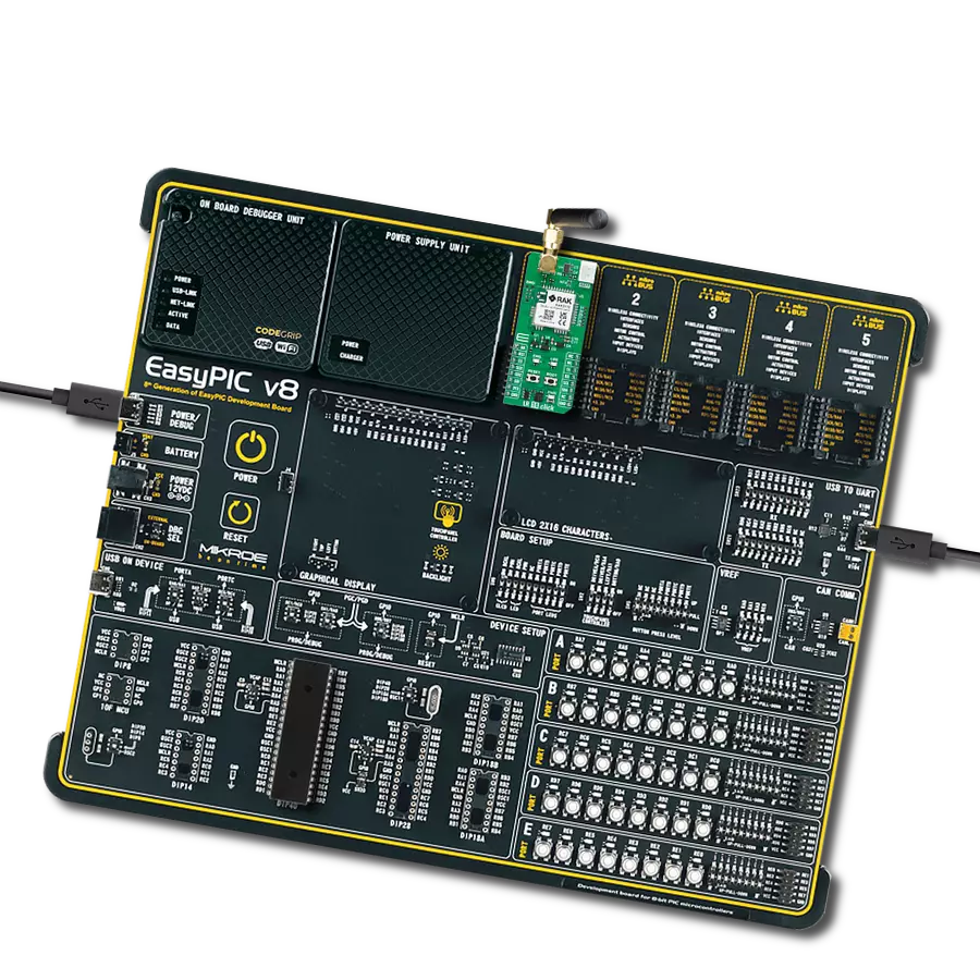
Fusion for TIVA v8 is a development board specially designed for the needs of rapid development of embedded applications. It supports a wide range of microcontrollers, such as different 32-bit ARM® Cortex®-M based MCUs from Texas Instruments, regardless of their number of pins, and a broad set of unique functions, such as the first-ever embedded debugger/programmer over a WiFi network. The development board is well organized and designed so that the end-user has all the necessary elements, such as switches, buttons, indicators, connectors, and others, in one place. Thanks to innovative manufacturing technology, Fusion for TIVA v8 provides a fluid and immersive working experience, allowing access
anywhere and under any circumstances at any time. Each part of the Fusion for TIVA v8 development board contains the components necessary for the most efficient operation of the same board. An advanced integrated CODEGRIP programmer/debugger module offers many valuable programming/debugging options, including support for JTAG, SWD, and SWO Trace (Single Wire Output)), and seamless integration with the Mikroe software environment. Besides, it also includes a clean and regulated power supply module for the development board. It can use a wide range of external power sources, including a battery, an external 12V power supply, and a power source via the USB Type-C (USB-C) connector.
Communication options such as USB-UART, USB HOST/DEVICE, CAN (on the MCU card, if supported), and Ethernet is also included. In addition, it also has the well-established mikroBUS™ standard, a standardized socket for the MCU card (SiBRAIN standard), and two display options for the TFT board line of products and character-based LCD. Fusion for TIVA v8 is an integral part of the Mikroe ecosystem for rapid development. Natively supported by Mikroe software tools, it covers many aspects of prototyping and development thanks to a considerable number of different Click boards™ (over a thousand boards), the number of which is growing every day.

Microcontroller Overview
MCU Card / MCU
Type
8th Generation
Architecture
ARM Cortex-M4
MCU Memory (KB)
256
Silicon Vendor
Texas Instruments
Pin count
100
RAM (Bytes)
32768
You complete me!
Accessories
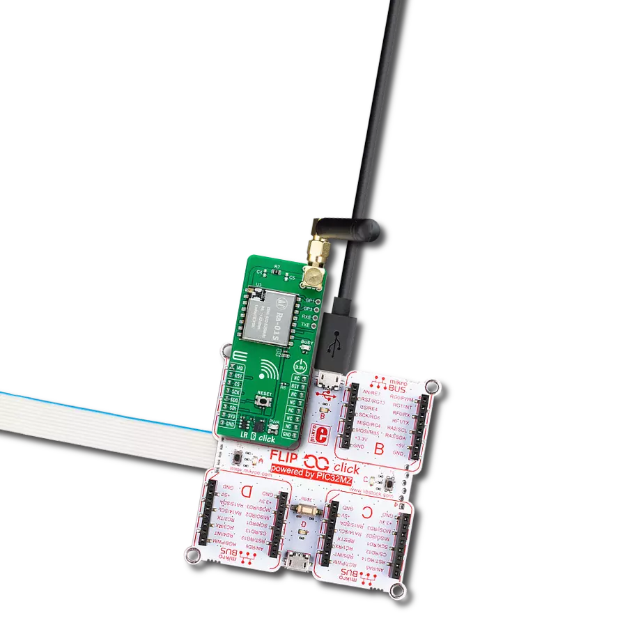
868MHz right-angle rubber antenna is a compact and versatile solution for wireless communication. Operating within the frequency range of 868-915MHz, it ensures optimal signal reception and transmission. With a 50-ohm impedance, it's compatible with various devices and systems. This antenna boasts a 2dB gain, enhancing signal strength and extending communication range. Its vertical polarization further contributes to signal clarity. Designed to handle up to 50W of input power, it's a robust choice for various applications. Measuring just 48mm in length, this antenna is both discreet and practical. Its SMA male connector ensures a secure and reliable connection to your equipment. Whether you're working with IoT devices, remote sensors, or other wireless technologies, the 868MHz right-angle antenna offers the performance and flexibility you need for seamless communication.

Used MCU Pins
mikroBUS™ mapper
Take a closer look
Click board™ Schematic

Step by step
Project assembly

Start by selecting your development board and Click board™. Begin with the Fusion for Tiva v8 as your development board.


Software Support
Library Description
This library contains API for LR 14 Click driver.
Key functions:
lr14_cmd_run- This function sends a specified command to the click module.lr14_cmd_set- This function sets a value to a specified command of the click module.lr14_cmd_get- This function is used to get the value of a given command from the click module.
Open Source
Code example
The complete application code and a ready-to-use project are available through the NECTO Studio Package Manager for direct installation in the NECTO Studio. The application code can also be found on the MIKROE GitHub account.
/*!
 * @file main.c
 * @brief LR 14 Click Example.
 *
 * # Description
 * This example demonstrates the use of LR 14 Click board by showing
 * the communication between two Click boards configured in P2P network mode.
 *
 * The demo application is composed of two sections :
 *
 * ## Application Init
 * Initializes the driver and logger.
 *
 * ## Application Task
 * Application task is split in few stages:
 *  - LR14_POWER_UP:
 * Powers up the device, performs a device factory reset and reads system information.
 *  - LR14_CONFIG_EXAMPLE:
 * Configures device for the LoRa P2P network mode.
 *  - LR14_EXAMPLE:
 * Performs a LoRa P2P example by exchanging messages with another LR 14 Click board.
 *
 * ## Additional Function
 * - static void lr14_clear_app_buf ( void )
 * - static void lr14_log_app_buf ( void )
 * - static err_t lr14_process ( lr14_t *ctx )
 * - static err_t lr14_read_response ( lr14_t *ctx, uint8_t *rsp )
 * - static err_t lr14_power_up ( lr14_t *ctx )
 * - static err_t lr14_config_example ( lr14_t *ctx )
 * - static err_t lr14_example ( lr14_t *ctx )
 *
 * @author Stefan Filipovic
 *
 */

#include "board.h"
#include "log.h"
#include "lr14.h"
#include "conversions.h"
#include "generic_pointer.h"

#define DEMO_TEXT_MESSAGE   "MIKROE - LR 14 Click board"

static lr14_t lr14;
static log_t logger;

// Application buffer size
#define APP_BUFFER_SIZE     600
#define PROCESS_BUFFER_SIZE 200

static uint8_t app_buf[ APP_BUFFER_SIZE ] = { 0 };
static int32_t app_buf_len = 0;

/**
 * @brief Example states.
 * @details Predefined enum values for application example state.
 */
typedef enum
{
    LR14_POWER_UP = 1,
    LR14_CONFIG_EXAMPLE,
    LR14_EXAMPLE

} lr14_app_state_t;

static lr14_app_state_t app_state = LR14_POWER_UP;

/**
 * @brief LR 14 clearing application buffer.
 * @details This function clears memory of application buffer and reset its length.
 * @note None.
 */
static void lr14_clear_app_buf ( void );

/**
 * @brief LR 14 log application buffer.
 * @details This function logs data from application buffer to USB UART.
 * @note None.
 */
static void lr14_log_app_buf ( void );

/**
 * @brief LR 14 data reading function.
 * @details This function reads data from device and concatenates data to application buffer.
 * @param[in] ctx : Click context object.
 * See #lr14_t object definition for detailed explanation.
 * @return @li @c  0 - Read some data.
 *         @li @c -1 - Nothing is read.
 * See #err_t definition for detailed explanation.
 * @note None.
 */
static err_t lr14_process ( lr14_t *ctx );

/**
 * @brief LR 14 read response function.
 * @details This function waits for a response message, reads and displays it on the USB UART.
 * @param[in] ctx : Click context object.
 * See #lr14_t object definition for detailed explanation.
 * @param[in] rsp  Expected response.
 * @return @li @c  0 - OK response.
 *         @li @c -2 - Timeout error.
 *         @li @c -3 - Command error.
 *         @li @c -4 - Unknown error.
 * See #err_t definition for detailed explanation.
 * @note None.
 */
static err_t lr14_read_response ( lr14_t *ctx, uint8_t *rsp );

/**
 * @brief LR 14 power up function.
 * @details This function powers up the device, performs device factory reset and reads system information.
 * @param[in] ctx : Click context object.
 * See #lr14_t object definition for detailed explanation.
 * @return @li @c    0 - OK.
 *         @li @c != 0 - Read response error.
 * See #err_t definition for detailed explanation.
 * @note None.
 */
static err_t lr14_power_up ( lr14_t *ctx );

/**
 * @brief LR 14 config example function.
 * @details This function configures device for LoRa P2P example.
 * @param[in] ctx : Click context object.
 * See #lr14_t object definition for detailed explanation.
 * @return @li @c    0 - OK.
 *         @li @c != 0 - Read response error.
 * See #err_t definition for detailed explanation.
 * @note None.
 */
static err_t lr14_config_example ( lr14_t *ctx );

/**
 * @brief LR 14 example function.
 * @details This function performs a LoRa P2P example by exchanging messages with another LR 14 Click board.
 * @param[in] ctx : Click context object.
 * See #lr14_t object definition for detailed explanation.
 * @return @li @c    0 - OK.
 *         @li @c != 0 - Read response error.
 * See #err_t definition for detailed explanation.
 * @note None.
 */
static err_t lr14_example ( lr14_t *ctx );

void application_init ( void )
{
    log_cfg_t log_cfg;  /**< Logger config object. */
    lr14_cfg_t lr14_cfg;  /**< Click config object. */

    /**
     * Logger initialization.
     * Default baud rate: 115200
     * Default log level: LOG_LEVEL_DEBUG
     * @note If USB_UART_RX and USB_UART_TX
     * are defined as HAL_PIN_NC, you will
     * need to define them manually for log to work.
     * See @b LOG_MAP_USB_UART macro definition for detailed explanation.
     */
    LOG_MAP_USB_UART( log_cfg );
    log_init( &logger, &log_cfg );
    log_info( &logger, " Application Init " );

    // Click initialization.
    lr14_cfg_setup( &lr14_cfg );
    LR14_MAP_MIKROBUS( lr14_cfg, MIKROBUS_1 );
    if ( UART_ERROR == lr14_init( &lr14, &lr14_cfg ) )
    {
        log_error( &logger, " Communication init." );
        for ( ; ; );
    }

    log_info( &logger, " Application Task " );

    app_state = LR14_POWER_UP;
    log_printf( &logger, ">>> APP STATE - POWER UP <<<\r\n\n" );
}

void application_task ( void )
{
    switch ( app_state )
    {
        case LR14_POWER_UP:
        {
            if ( LR14_OK == lr14_power_up( &lr14 ) )
            {
                app_state = LR14_CONFIG_EXAMPLE;
                log_printf( &logger, ">>> APP STATE - CONFIG EXAMPLE <<<\r\n\n" );
            }
            break;
        }
        case LR14_CONFIG_EXAMPLE:
        {
            if ( LR14_OK == lr14_config_example( &lr14 ) )
            {
                app_state = LR14_EXAMPLE;
                log_printf( &logger, ">>> APP STATE - EXAMPLE <<<\r\n\n" );
            }
            break;
        }
        case LR14_EXAMPLE:
        {
            lr14_example( &lr14 );
            break;
        }
        default:
        {
            log_error( &logger, " APP STATE." );
            break;
        }
    }
}

int main ( void )
{
    /* Do not remove this line or clock might not be set correctly. */
    #ifdef PREINIT_SUPPORTED
    preinit();
    #endif

    application_init( );

    for ( ; ; )
    {
        application_task( );
    }

    return 0;
}

static void lr14_clear_app_buf ( void )
{
    memset( app_buf, 0, app_buf_len );
    app_buf_len = 0;
}

static void lr14_log_app_buf ( void )
{
    for ( int32_t buf_cnt = 0; buf_cnt < app_buf_len; buf_cnt++ )
    {
        log_printf( &logger, "%c", app_buf[ buf_cnt ] );
    }
}

static err_t lr14_process ( lr14_t *ctx )
{
    uint8_t rx_buf[ PROCESS_BUFFER_SIZE ] = { 0 };
    int32_t overflow_bytes = 0;
    int32_t rx_cnt = 0;
    int32_t rx_size = lr14_generic_read( ctx, rx_buf, PROCESS_BUFFER_SIZE );
    if ( ( rx_size > 0 ) && ( rx_size <= APP_BUFFER_SIZE ) )
    {
        if ( ( app_buf_len + rx_size ) > APP_BUFFER_SIZE )
        {
            overflow_bytes = ( app_buf_len + rx_size ) - APP_BUFFER_SIZE;
            app_buf_len = APP_BUFFER_SIZE - rx_size;
            memmove ( app_buf, &app_buf[ overflow_bytes ], app_buf_len );
            memset ( &app_buf[ app_buf_len ], 0, overflow_bytes );
        }
        for ( rx_cnt = 0; rx_cnt < rx_size; rx_cnt++ )
        {
            if ( rx_buf[ rx_cnt ] )
            {
                app_buf[ app_buf_len++ ] = rx_buf[ rx_cnt ];
            }
        }
        return LR14_OK;
    }
    return LR14_ERROR;
}

static err_t lr14_read_response ( lr14_t *ctx, uint8_t *rsp )
{
    #define READ_RESPONSE_TIMEOUT_MS    120000
    uint32_t timeout_cnt = 0;
    lr14_clear_app_buf ( );
    lr14_process( ctx );
    while ( ( 0 == strstr( app_buf, rsp ) ) &&
            ( 0 == strstr( app_buf, LR14_RSP_ERROR ) ) &&
            ( 0 == strstr( app_buf, LR14_RSP_PARAM_ERROR ) ) &&
            ( 0 == strstr( app_buf, LR14_RSP_BUSY_ERROR ) ) &&
            ( 0 == strstr( app_buf, LR14_RSP_TEST_PARAM_OVERFLOW ) ) &&
            ( 0 == strstr( app_buf, LR14_RSP_NO_CLASSB_ENABLE ) ) &&
            ( 0 == strstr( app_buf, LR14_RSP_NO_NETWORK_JOINED ) ) &&
            ( 0 == strstr( app_buf, LR14_RSP_RX_ERROR ) ) )
    {
        lr14_process( ctx );
        if ( timeout_cnt++ > READ_RESPONSE_TIMEOUT_MS )
        {
            lr14_clear_app_buf( );
            log_error( &logger, " Timeout!" );
            return LR14_ERROR_TIMEOUT;
        }
        Delay_ms( 1 );
    }
    Delay_ms ( 200 );
    lr14_process( ctx );
    if ( strstr( app_buf, rsp ) )
    {
        lr14_log_app_buf( );
        log_printf( &logger, "--------------------------------\r\n" );
        return LR14_OK;
    }
    log_error( &logger, " CMD!" );
    return LR14_ERROR_CMD;
}

static err_t lr14_power_up ( lr14_t *ctx )
{
    err_t error_flag = LR14_OK;

    log_printf( &logger, ">>> Reset device.\r\n" );
    lr14_reset_device( &lr14 );
    while ( LR14_OK == lr14_process( ctx ) )
    {
        lr14_log_app_buf( );
        lr14_clear_app_buf ( );
    }
    log_printf( &logger, "--------------------------------\r\n" );

    log_printf( &logger, ">>> Check communication.\r\n" );
    lr14_cmd_run( &lr14, LR14_CMD_AT );
    error_flag |= lr14_read_response( &lr14, LR14_RSP_OK );

    log_printf( &logger, ">>> Factory reset.\r\n" );
    lr14_cmd_run( &lr14, LR14_CMD_FACTORY_RESET );
    error_flag |= lr14_read_response( &lr14, LR14_RSP_INITIAL );

    log_printf( &logger, ">>> Toggle command echo.\r\n" );
    lr14_cmd_run( &lr14, LR14_CMD_TOGGLE_ECHO );
    error_flag |= lr14_read_response( &lr14, LR14_RSP_OK );

    log_printf( &logger, ">>> Get device model ID.\r\n" );
    lr14_cmd_get( ctx, LR14_CMD_GET_MODEL_ID );
    error_flag |= lr14_read_response( ctx, LR14_RSP_OK );

    log_printf( &logger, ">>> Get device firmware version.\r\n" );
    lr14_cmd_get( ctx, LR14_CMD_GET_FW_VERSION );
    error_flag |= lr14_read_response( ctx, LR14_RSP_OK );

    log_printf( &logger, ">>> Get device serial number.\r\n" );
    lr14_cmd_get( ctx, LR14_CMD_GET_SERIAL_NUMBER );
    error_flag |= lr14_read_response( ctx, LR14_RSP_OK );

    return error_flag;
}

static err_t lr14_config_example ( lr14_t *ctx )
{
    err_t error_flag = LR14_OK;
    #define NETWORK_WORK_MODE_P2P_LORA "0"
    log_printf( &logger, ">>> Get network work mode.\r\n" );
    lr14_cmd_get( ctx, LR14_CMD_NETWORK_WORK_MODE );
    error_flag |= lr14_read_response( ctx, LR14_RSP_OK );
    if ( !strstr( app_buf, NETWORK_WORK_MODE_P2P_LORA ) )
    {
        log_printf( &logger, ">>> Set LoRa P2P network work mode.\r\n" );
        lr14_cmd_set( ctx, LR14_CMD_NETWORK_WORK_MODE, NETWORK_WORK_MODE_P2P_LORA );
        error_flag |= lr14_read_response( ctx, LR14_RSP_OK );
    }
    #define P2P_MODE_FREQUENCY "868000000"
    log_printf( &logger, ">>> Set P2P mode frequency to 868 MHz.\r\n" );
    lr14_cmd_set( ctx, LR14_CMD_P2P_MODE_FREQUENCY, P2P_MODE_FREQUENCY );
    error_flag |= lr14_read_response( ctx, LR14_RSP_OK );

    #define P2P_MODE_SPREADING_FACTOR "12"
    log_printf( &logger, ">>> Set P2P mode spreading factor to 12.\r\n" );
    lr14_cmd_set( ctx, LR14_CMD_P2P_MODE_SPREADING_FACTOR, P2P_MODE_SPREADING_FACTOR );
    error_flag |= lr14_read_response( ctx, LR14_RSP_OK );

    #define P2P_MODE_BANDWIDTH "0"
    log_printf( &logger, ">>> Set P2P mode bandwidth to 125 kHz.\r\n" );
    lr14_cmd_set( ctx, LR14_CMD_P2P_MODE_BANDWIDTH, P2P_MODE_BANDWIDTH );
    error_flag |= lr14_read_response( ctx, LR14_RSP_OK );

    #define P2P_MODE_CODE_RATE "0"
    log_printf( &logger, ">>> Set P2P mode code rate to 4/5.\r\n" );
    lr14_cmd_set( ctx, LR14_CMD_P2P_MODE_CODE_RATE, P2P_MODE_CODE_RATE );
    error_flag |= lr14_read_response( ctx, LR14_RSP_OK );

    #define P2P_MODE_PREAMBLE_LENGTH "8"
    log_printf( &logger, ">>> Set P2P mode preamble length to 8.\r\n" );
    lr14_cmd_set( ctx, LR14_CMD_P2P_MODE_PREAMBLE_LENGTH, P2P_MODE_PREAMBLE_LENGTH );
    error_flag |= lr14_read_response( ctx, LR14_RSP_OK );

    #define P2P_MODE_TX_POWER "22"
    log_printf( &logger, ">>> Set P2P mode TX power to 22 dBm.\r\n" );
    lr14_cmd_set( ctx, LR14_CMD_P2P_MODE_TX_POWER, P2P_MODE_TX_POWER );
    error_flag |= lr14_read_response( ctx, LR14_RSP_OK );

    return error_flag;
}

static err_t lr14_example ( lr14_t *ctx )
{
    err_t error_flag = LR14_OK;
    uint8_t msg_hex[ 201 ] = { 0 };
    uint8_t byte_hex[ 3 ] = { 0 };
    uint8_t rssi[ 10 ] = { 0 };
    uint8_t snr[ 10 ] = { 0 };
    uint8_t cnt = 0;

    memset( msg_hex, 0, sizeof ( msg_hex ) );
    for ( cnt = 0; ( cnt < strlen ( DEMO_TEXT_MESSAGE ) ) && ( cnt < 100 ); cnt++ )
    {
        uint8_to_hex ( DEMO_TEXT_MESSAGE[ cnt ], byte_hex );
        strcat ( msg_hex, byte_hex );
    }
    log_printf( &logger, ">>> Send message: \"%s\".\r\n", ( char * ) DEMO_TEXT_MESSAGE );
    lr14_cmd_set( ctx, LR14_CMD_P2P_TX_MODE, msg_hex );
    error_flag |= lr14_read_response( ctx, LR14_EVT_TX_P2P );

    memset( msg_hex, 0, sizeof ( msg_hex ) );
    #define P2P_RX_MODE_TIMEOUT "30000"
    log_printf( &logger, ">>> Go to P2P RX mode with a 30s timeout.\r\n" );
    lr14_cmd_set( ctx, LR14_CMD_P2P_RX_MODE, P2P_RX_MODE_TIMEOUT );
    error_flag |= lr14_read_response( ctx, LR14_EVT_RX_P2P );

    if ( !strstr( app_buf, LR14_EVT_RX_P2P_ERROR ) &&
         !strstr( app_buf, LR14_EVT_RX_P2P_TIMEOUT ) )
    {
        uint8_t * __generic_ptr start_ptr = strstr( app_buf, LR14_EVT_RX_P2P );
        uint8_t * __generic_ptr end_ptr = NULL;
        if ( start_ptr )
        {
            start_ptr = start_ptr + strlen ( LR14_EVT_RX_P2P ) + 1;
            end_ptr = strstr ( start_ptr, ":" );
            memcpy ( rssi, start_ptr, end_ptr - start_ptr );

            start_ptr = end_ptr + 1;
            end_ptr = strstr ( start_ptr, ":" );
            memcpy ( snr, start_ptr, end_ptr - start_ptr );

            start_ptr = end_ptr + 1;
            end_ptr = strstr ( start_ptr, "\r\n" );
            memcpy ( msg_hex, start_ptr, end_ptr - start_ptr );

            for ( cnt = 0; cnt < strlen ( msg_hex ); cnt += 2 )
            {
                msg_hex[ cnt / 2 ] = hex_to_uint8 ( &msg_hex [ cnt ] );
            }
            msg_hex[ cnt / 2 ] = 0;
            log_printf( &logger, ">>> Parse received message.\r\n" );
            log_printf ( &logger, " Message: %s\r\n", msg_hex );
            log_printf ( &logger, " RSSI: %s\r\n", rssi );
            log_printf ( &logger, " SNR: %s\r\n", snr );
            log_printf( &logger, "--------------------------------\r\n" );
        }
    }

    return error_flag;
}

// ------------------------------------------------------------------------ END
Additional Support
Resources
Category:LoRa