Experience the future of visual excellence with WS2812 and TM4C1299KCZAD
Pixels come alive: 16 RGB elements in harmony!

Published Sep 04, 2023
Click board™
4X4 RGB Click
Dev. board
Fusion for ARM v8
Compiler
NECTO Studio
MCU
TM4C1299KCZAD
Our 4x4 display matrix featuring 16 'intelligent' RGB elements opens the door to a world of dynamic visual experiences, making it the ideal choice for projects requiring vivid and customizable displays
A
A
Hardware Overview
How does it work?
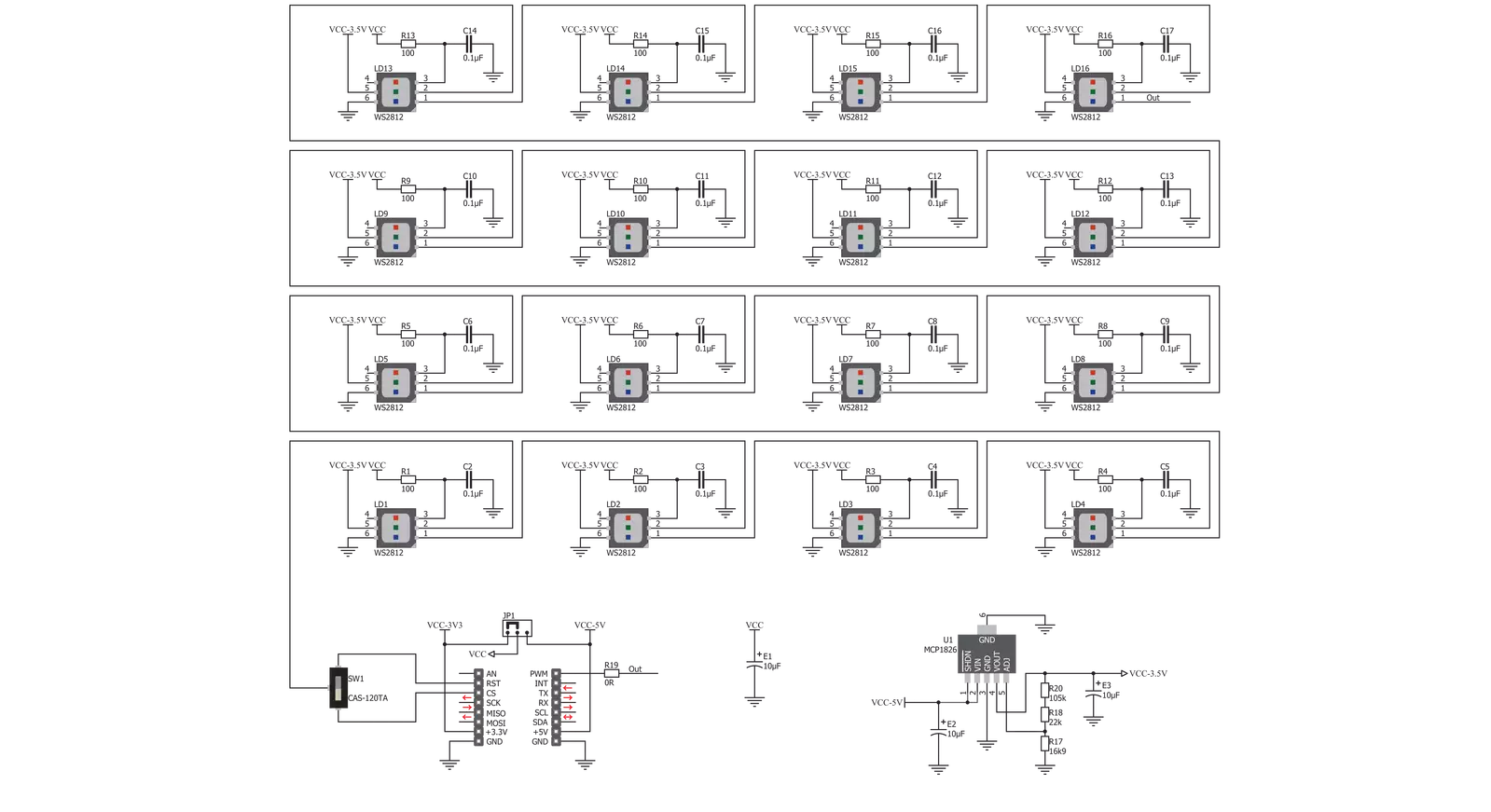
4x4 RGB Click is based on the WS2812, intelligent LED elements with an integrated control from Worldsemi. Thanks to the high brightness of the LED elements and their color consistency, this Click board™ can be used in various decorative applications, simple pattern displays, and color number displays, and due to the cascade nature of the Click board™ itself, they can even be used for building larger screens and displays. These LED elements are composed of red, green, and blue LED segments, forming an RGB LED cell, with their intensities controlled by the integrated logic section. This integrated control section allows separate 8-bit control of each RGB segment, forming a 24-bit color palette and allowing
16,777,216 different colors to be displayed. The power supply for the LED elements is provided by the MCP1826, a low-voltage, low-quiescent current LDO regulator from Microchip, which can provide current up to 1A. While the logic voltage can be selected between 3.3V and 5V rails, the LED power supply is derived from the 5V mikroBUS™ power rail. It is reduced to 3.5V by the LDO and distributed to the LED supply inputs of the WS2812 elements. 4x4 RGB Click uses a single line to communicate with the host MCU. The onboard IN switch between the IN1 and IN2 pins can select the communication line. The OUT pin of the mikroBUS™ allows cascading of multiple 4x4 RGB Click devices. It simply routes the data line back to
the mikroBUS™, allowing it to be re-used for the next 4x4 RGB click, and so on. The length of the whole chain is limited only by the communication speed required to scan through all the LED devices in order to maintain a reasonable refresh speed. This Click board™ can operate with either 3.3V or 5V logic voltage levels selected via the IO LEVEL jumper. This way, both 3.3V and 5V capable MCUs can use the communication lines properly. Also, this Click board™ comes equipped with a library containing easy-to-use functions and an example code that can be used as a reference for further development.

Features overview
Development board
Fusion for ARM v8 is a development board specially designed for the needs of rapid development of embedded applications. It supports a wide range of microcontrollers, such as different ARM® Cortex®-M based MCUs regardless of their number of pins, and a broad set of unique functions, such as the first-ever embedded debugger/programmer over WiFi. The development board is well organized and designed so that the end-user has all the necessary elements, such as switches, buttons, indicators, connectors, and others, in one place. Thanks to innovative manufacturing technology, Fusion for ARM v8 provides a fluid and immersive working experience, allowing access anywhere and under any
circumstances at any time. Each part of the Fusion for ARM v8 development board contains the components necessary for the most efficient operation of the same board. An advanced integrated CODEGRIP programmer/debugger module offers many valuable programming/debugging options, including support for JTAG, SWD, and SWO Trace (Single Wire Output)), and seamless integration with the Mikroe software environment. Besides, it also includes a clean and regulated power supply module for the development board. It can use a wide range of external power sources, including a battery, an external 12V power supply, and a power source via the USB Type-C (USB-C) connector.
Communication options such as USB-UART, USB HOST/DEVICE, CAN (on the MCU card, if supported), and Ethernet is also included. In addition, it also has the well-established mikroBUS™ standard, a standardized socket for the MCU card (SiBRAIN standard), and two display options for the TFT board line of products and character-based LCD. Fusion for ARM v8 is an integral part of the Mikroe ecosystem for rapid development. Natively supported by Mikroe software tools, it covers many aspects of prototyping and development thanks to a considerable number of different Click boards™ (over a thousand boards), the number of which is growing every day.

Microcontroller Overview
MCU Card / MCU
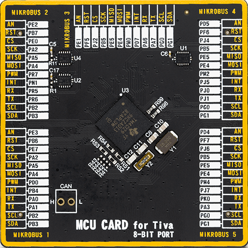
Type
8th Generation
Architecture
ARM Cortex-M4
MCU Memory (KB)
512
Silicon Vendor
Texas Instruments
Pin count
212
RAM (Bytes)
262144
Used MCU Pins
mikroBUS™ mapper
Take a closer look
Click board™ Schematic
Step by step
Project assembly

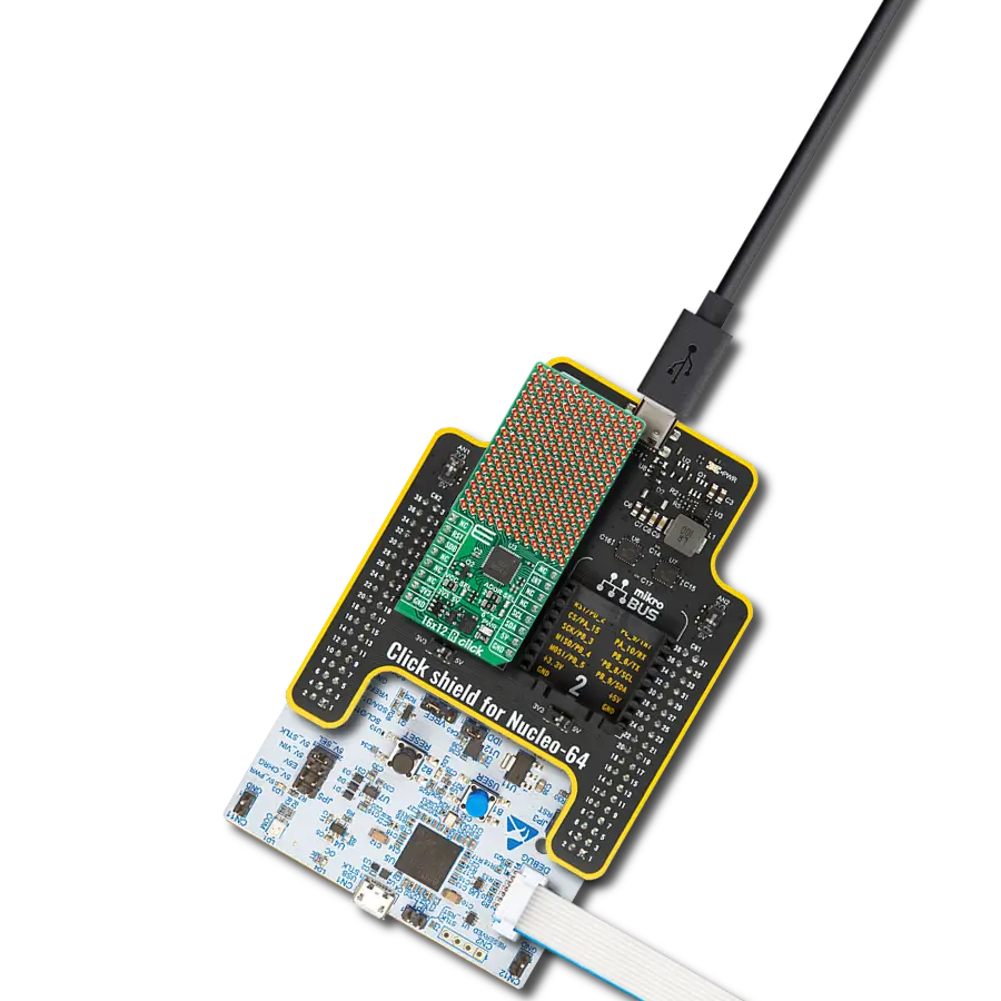
Start by selecting your development board and Click board™. Begin with the Fusion for ARM v8 as your development board.


Track your results in real time
Application Output
1. Application Output - In Debug mode, the 'Application Output' window enables real-time data monitoring, offering direct insight into execution results. Ensure proper data display by configuring the environment correctly using the provided tutorial.

2. UART Terminal - Use the UART Terminal to monitor data transmission via a USB to UART converter, allowing direct communication between the Click board™ and your development system. Configure the baud rate and other serial settings according to your project's requirements to ensure proper functionality. For step-by-step setup instructions, refer to the provided tutorial.

3. Plot Output - The Plot feature offers a powerful way to visualize real-time sensor data, enabling trend analysis, debugging, and comparison of multiple data points. To set it up correctly, follow the provided tutorial, which includes a step-by-step example of using the Plot feature to display Click board™ readings. To use the Plot feature in your code, use the function: plot(*insert_graph_name*, variable_name);. This is a general format, and it is up to the user to replace 'insert_graph_name' with the actual graph name and 'variable_name' with the parameter to be displayed.

Software Support
Library Description
This library contains API for 4x4 RGB Click driver.
Key functions:
c4x4rgb_set_diode- This function allows to set color of one diodec4x4rgb_fill_screen- This function sets every diode on selected color
Open Source
Code example
The complete application code and a ready-to-use project are available through the NECTO Studio Package Manager for direct installation in the NECTO Studio. The application code can also be found on the MIKROE GitHub account.
/*!
 * \file
 * \brief 4x4 RGB Click example
 *
 * # Description
 * This application is used for powering 4x4 RGB LED matrix.
 *
 * The demo application is composed of two sections :
 *
 * ## Application Init
 * Initialization driver enables - GPIO.
 *
 * ## Application Task
 * This is an example which demonstrates the use of 4x4 RGB Click board.
 * This simple example shows all ten numbers in different colors on 4x4 RGB Click.
 * The 4x4 RGB Click carries a matrix of 16 RGB LEDs and an MCP1826 low dropout regulator.
 * These LEDs actually consist of three single colored LEDs ( Red, Green and Blue ) in a single package.
 * Various colors can be reproduced by mixing the intensity of each LED.
 *
 * @note
 * Make sure the logic delays are defined for your system in the c4x4rgb_delays.h file.
 *
 * **Diodes layout:**
 * ----------------------
 * | 13 | 14 | 15 | 16  |
 * |--------------------|
 * |  9 | 10 | 11 | 12  |
 * |--------------------|
 * |  5 |  6 |  7 |  8  |
 * |--------------------|
 * |  1 |  2 |  3 |  4  |
 * ----------------------
 *
 * \author MikroE Team
 *
 */
#include "board.h"
#include "c4x4rgb.h"
#include "c4x4rgb_delays.h"

#define SNAKE_DELAY     50
#define MASH_DELAY      100

static c4x4rgb_t c4x4rgb;

static void c4x4rgb_logic_zero ( void );

static void c4x4rgb_logic_one ( void );

static void c4x4rgb_color_mash ( void );

static void c4x4rgb_snake ( uint32_t snake_color );

static void c4x4rgb_snake_return ( uint32_t snake_color );

void application_init ( void )
{
    c4x4rgb_cfg_t cfg;

    //  Click initialization.
    c4x4rgb_cfg_setup( &cfg, &c4x4rgb_logic_zero, &c4x4rgb_logic_one, C4X4RGB_CTRL_PIN_IN1 );
    C4X4RGB_MAP_MIKROBUS( cfg, MIKROBUS_1 );
    c4x4rgb_init( &c4x4rgb, &cfg );

    c4x4rgb_fill_screen( &c4x4rgb, C4X4RGB_COLOR_WHITE );
    Delay_ms ( 100 );

    c4x4rgb_color_mash();
    Delay_ms ( 1000 );
    Delay_ms ( 1000 );
}

void application_task ( void )
{
    c4x4rgb_snake( C4X4RGB_COLOR_BLUE );
    Delay_ms ( 500 );

    c4x4rgb_snake_return( C4X4RGB_COLOR_LIGHT_BLUE );
    Delay_ms ( 1000 );

    c4x4rgb_snake(  C4X4RGB_COLOR_GREEN );
    Delay_ms ( 500 );

    c4x4rgb_snake_return( C4X4RGB_COLOR_YELLOW );
    Delay_ms ( 1000 );

    c4x4rgb_snake( C4X4RGB_COLOR_RED );
    Delay_ms ( 500 );

    c4x4rgb_snake_return( C4X4RGB_COLOR_PURPLE );
    Delay_ms ( 1000 );

    c4x4rgb_fill_screen( &c4x4rgb, C4X4RGB_COLOR_WHITE );
    Delay_ms ( 100 );
}

int main ( void )
{
    /* Do not remove this line or clock might not be set correctly. */
    #ifdef PREINIT_SUPPORTED
    preinit();
    #endif

    application_init( );

    for ( ; ; )
    {
        application_task( );
    }

    return 0;
}


static void c4x4rgb_logic_zero ( void )
{
    hal_ll_gpio_set_pin_output( &c4x4rgb.ctrl_pin.pin );
    DELAY_TOH;
    hal_ll_gpio_clear_pin_output( &c4x4rgb.ctrl_pin.pin );
    DELAY_TOL;
}

static void c4x4rgb_logic_one ( void )
{
    hal_ll_gpio_set_pin_output( &c4x4rgb.ctrl_pin.pin );
    DELAY_T1H;
    hal_ll_gpio_clear_pin_output( &c4x4rgb.ctrl_pin.pin );
    DELAY_T1L;
}

static void c4x4rgb_color_mash ( void )
{
    c4x4rgb_set_diode( &c4x4rgb, 1, C4X4RGB_COLOR_BLUE );
    Delay_ms ( MASH_DELAY );
    c4x4rgb_set_diode( &c4x4rgb, 2, C4X4RGB_COLOR_YELLOW );
    Delay_ms ( MASH_DELAY );
    c4x4rgb_set_diode( &c4x4rgb, 3, C4X4RGB_COLOR_LIGHT_BLUE );
    Delay_ms ( MASH_DELAY );
    c4x4rgb_set_diode( &c4x4rgb, 4, C4X4RGB_COLOR_WHITE );
    Delay_ms ( MASH_DELAY );
    c4x4rgb_set_diode( &c4x4rgb, 5, C4X4RGB_COLOR_PURPLE );
    Delay_ms ( MASH_DELAY );
    c4x4rgb_set_diode( &c4x4rgb, 6, C4X4RGB_COLOR_GREEN );
    Delay_ms ( MASH_DELAY );
    c4x4rgb_set_diode( &c4x4rgb, 7, C4X4RGB_COLOR_RED );
    Delay_ms ( MASH_DELAY );
    c4x4rgb_set_diode( &c4x4rgb, 8, C4X4RGB_COLOR_BLUE );
    Delay_ms ( MASH_DELAY );
    c4x4rgb_set_diode( &c4x4rgb, 9, C4X4RGB_COLOR_YELLOW );
    Delay_ms ( MASH_DELAY );
    c4x4rgb_set_diode( &c4x4rgb, 10, C4X4RGB_COLOR_LIGHT_BLUE );
    Delay_ms ( MASH_DELAY );
    c4x4rgb_set_diode( &c4x4rgb, 11, C4X4RGB_COLOR_WHITE );
    Delay_ms ( MASH_DELAY );
    c4x4rgb_set_diode( &c4x4rgb, 12, C4X4RGB_COLOR_PURPLE );
    Delay_ms ( MASH_DELAY );
    c4x4rgb_set_diode( &c4x4rgb, 13, C4X4RGB_COLOR_GREEN );
    Delay_ms ( MASH_DELAY );
    c4x4rgb_set_diode( &c4x4rgb, 14, C4X4RGB_COLOR_RED );
    Delay_ms ( MASH_DELAY );
    c4x4rgb_set_diode( &c4x4rgb, 15, C4X4RGB_COLOR_BLUE );
    Delay_ms ( MASH_DELAY );
    c4x4rgb_set_diode( &c4x4rgb, 16, C4X4RGB_COLOR_RED );
    Delay_ms ( MASH_DELAY );
}

static void c4x4rgb_snake ( uint32_t snake_color )
{
    c4x4rgb_set_diode( &c4x4rgb, 4, snake_color );
    Delay_ms ( SNAKE_DELAY );
    c4x4rgb_set_diode( &c4x4rgb, 3, snake_color );
    Delay_ms ( SNAKE_DELAY );
    c4x4rgb_set_diode( &c4x4rgb, 2, snake_color );
    Delay_ms ( SNAKE_DELAY );
    c4x4rgb_set_diode( &c4x4rgb, 1, snake_color );
    Delay_ms ( SNAKE_DELAY );
    c4x4rgb_set_diode( &c4x4rgb, 5, snake_color );
    Delay_ms ( SNAKE_DELAY );
    c4x4rgb_set_diode( &c4x4rgb, 9, snake_color );
    Delay_ms ( SNAKE_DELAY );
    c4x4rgb_set_diode( &c4x4rgb, 13, snake_color );
    Delay_ms ( SNAKE_DELAY );
    c4x4rgb_set_diode( &c4x4rgb, 14, snake_color );
    Delay_ms ( SNAKE_DELAY );
    c4x4rgb_set_diode( &c4x4rgb, 15, snake_color );
    Delay_ms ( SNAKE_DELAY );
    c4x4rgb_set_diode( &c4x4rgb, 16, snake_color );
    Delay_ms ( SNAKE_DELAY );
    c4x4rgb_set_diode( &c4x4rgb, 12, snake_color );
    Delay_ms ( SNAKE_DELAY );
    c4x4rgb_set_diode( &c4x4rgb, 8, snake_color );
    Delay_ms ( SNAKE_DELAY );
    c4x4rgb_set_diode( &c4x4rgb, 7, snake_color );
    Delay_ms ( SNAKE_DELAY );
    c4x4rgb_set_diode( &c4x4rgb, 6, snake_color );
    Delay_ms ( SNAKE_DELAY );
    c4x4rgb_set_diode( &c4x4rgb, 10, snake_color );
    Delay_ms ( SNAKE_DELAY );
    c4x4rgb_set_diode( &c4x4rgb, 11, snake_color );
}

static void c4x4rgb_snake_return ( uint32_t snake_color )
{
    c4x4rgb_set_diode( &c4x4rgb, 11, snake_color );
    Delay_ms ( SNAKE_DELAY );
    c4x4rgb_set_diode( &c4x4rgb, 10, snake_color );
    Delay_ms ( SNAKE_DELAY );
    c4x4rgb_set_diode( &c4x4rgb, 6, snake_color );
    Delay_ms ( SNAKE_DELAY );
    c4x4rgb_set_diode( &c4x4rgb, 7, snake_color );
    Delay_ms ( SNAKE_DELAY );
    c4x4rgb_set_diode( &c4x4rgb, 8, snake_color );
    Delay_ms ( SNAKE_DELAY );
    c4x4rgb_set_diode( &c4x4rgb, 12, snake_color );
    Delay_ms ( SNAKE_DELAY );
    c4x4rgb_set_diode( &c4x4rgb, 16, snake_color );
    Delay_ms ( SNAKE_DELAY );
    c4x4rgb_set_diode( &c4x4rgb, 15, snake_color );
    Delay_ms ( SNAKE_DELAY );
    c4x4rgb_set_diode( &c4x4rgb, 14, snake_color );
    Delay_ms ( SNAKE_DELAY );
    c4x4rgb_set_diode( &c4x4rgb, 13, snake_color );
    Delay_ms ( SNAKE_DELAY );
    c4x4rgb_set_diode( &c4x4rgb, 9, snake_color );
    Delay_ms ( SNAKE_DELAY );
    c4x4rgb_set_diode( &c4x4rgb, 5, snake_color );
    Delay_ms ( SNAKE_DELAY );
    c4x4rgb_set_diode( &c4x4rgb, 1, snake_color );
    Delay_ms ( SNAKE_DELAY );
    c4x4rgb_set_diode( &c4x4rgb, 2, snake_color );
    Delay_ms ( SNAKE_DELAY );
    c4x4rgb_set_diode( &c4x4rgb, 3, snake_color );
    Delay_ms ( SNAKE_DELAY );
    c4x4rgb_set_diode( &c4x4rgb, 4, snake_color );
    Delay_ms ( SNAKE_DELAY );
}

// ------------------------------------------------------------------------ END
Additional Support
Resources
Category:LED Matrix