Manage I2C communications across multiple devices with TCA9548A and ATmega324P
8-in-1 bidirectional bliss

Published Sep 03, 2023
Click board™
I2C MUX 3 Click
Dev. board
EasyAVR v7
Compiler
NECTO Studio
MCU
ATmega324P
Unlock the power of bidirectional translating switches to seamlessly connect and control a wide array of I2C-enabled devices, simplifying your integration process
A
A
Hardware Overview
How does it work?
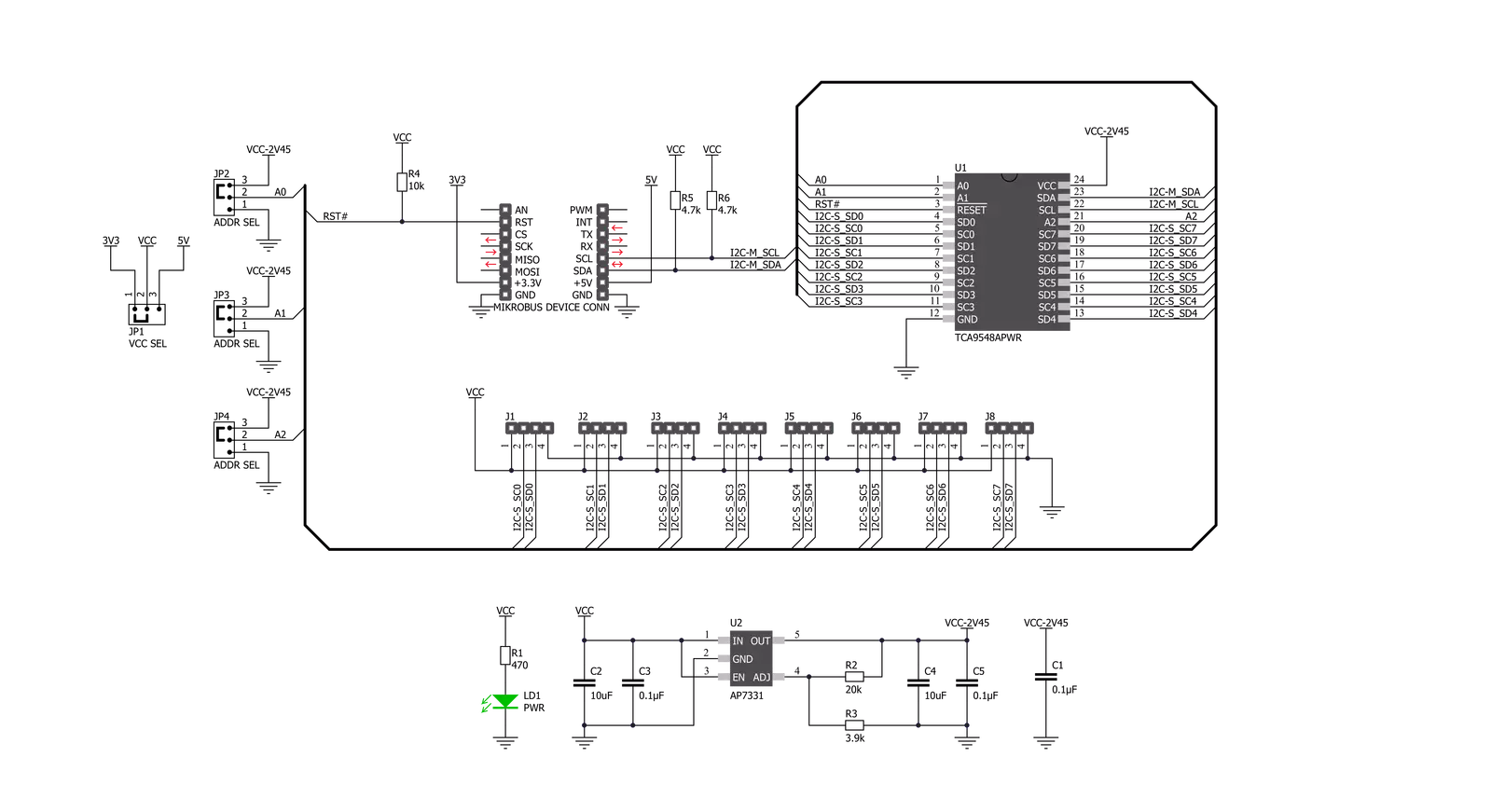
I2C MUX 3 Click is based on the TCA9548A, a low voltage eight bidirectional translating switch with an active-low reset input controlled through the I2C serial interface from Texas Instruments. The master SCL/SDA signal pair is directed to eight channels of slave devices, SC0/SD0-SC7/SD7, where any individual downstream channel can be selected and any combination of the eight channels. It features I2C control using a single 8-bit control register in which each bit controls the enabling and disabling of one of the corresponding eight switch channels for I2C data flow. This Click board™ includes a low dropout linear regulator AP7331 from Diodes Incorporated to provide the 2.45V supply voltage for the TCA9548A. When the TCA9548APWR is turned on for the first time or at any time, the device needs
to be reset by cycling the power supply, which means that the Power-On reset requirements must be followed to ensure the I2C bus logic is appropriately initialized. Additionally, suppose communication on the I2C bus enters a fault state. In that case, the TCA9548A can be reset to resume normal operation using the RST pin feature or by a Power-On reset, which results from cycling power to the device. I2C MUX 3 Click communicates with MCU using the standard I2C 2-Wire interface that supports Standard-Mode (100 kHz) and Fast-Mode (400 kHz) operations. The TCA9548A has a 7-bit slave address with the first five MSBs fixed to 1110. The address pins A0, A1, and A2 are programmed by the user and determine the value of the last three LSBs of the slave address, which can be selected by onboard SMD jumpers labeled as
ADDR SEL, allowing selection of the slave address LSBs. It also has an active-low reset signal routed on the RST pin of the mikroBUS™ socket used to recover from a bus-fault condition. When this signal is asserted LOW, the TCA9548A resets its registers alongside the I2C state machine and deselects all channels. This Click board™ can operate with either 3.3V or 5V logic voltage levels selected via the VCC SEL jumper. This way, both 3.3V and 5V capable MCUs can use the communication lines properly. More information about the TCA9548A can be found in the attached datasheet. Also, this Click board™ comes equipped with a library containing easy-to-use functions and an example code that can be used as a reference for further development.


Features overview
Development board
EasyAVR v7 is the seventh generation of AVR development boards specially designed for the needs of rapid development of embedded applications. It supports a wide range of 16-bit AVR microcontrollers from Microchip and has a broad set of unique functions, such as a powerful onboard mikroProg programmer and In-Circuit debugger over USB. The development board is well organized and designed so that the end-user has all the necessary elements in one place, such as switches, buttons, indicators, connectors, and others. With four different connectors for each port, EasyAVR v7 allows you to connect accessory boards, sensors, and custom electronics more
efficiently than ever. Each part of the EasyAVR v7 development board contains the components necessary for the most efficient operation of the same board. An integrated mikroProg, a fast USB 2.0 programmer with mikroICD hardware In-Circuit Debugger, offers many valuable programming/debugging options and seamless integration with the Mikroe software environment. Besides it also includes a clean and regulated power supply block for the development board. It can use a wide range of external power sources, including an external 12V power supply, 7-12V AC or 9-15V DC via DC connector/screw terminals, and a power source via the USB Type-B (USB-B)
connector. Communication options such as USB-UART and RS-232 are also included, alongside the well-established mikroBUS™ standard, three display options (7-segment, graphical, and character-based LCD), and several different DIP sockets which cover a wide range of 16-bit AVR MCUs. EasyAVR v7 is an integral part of the Mikroe ecosystem for rapid development. Natively supported by Mikroe software tools, it covers many aspects of prototyping and development thanks to a considerable number of different Click boards™ (over a thousand boards), the number of which is growing every day.

Microcontroller Overview
MCU Card / MCU

Architecture
AVR
MCU Memory (KB)
32
Silicon Vendor
Microchip
Pin count
40
RAM (Bytes)
2048
Used MCU Pins
mikroBUS™ mapper
Take a closer look
Click board™ Schematic
Step by step
Project assembly

Start by selecting your development board and Click board™. Begin with the EasyAVR v7 as your development board.


Software Support
Library Description
This library contains API for I2C MUX 3 Click driver.
Key functions:
i2cmux3_rd_slv- Slave Device Read functioni2cmux3_dev_enable- Device enable functioni2cmux3_hw_rst- Hardware reset function
Open Source
Code example
The complete application code and a ready-to-use project are available through the NECTO Studio Package Manager for direct installation in the NECTO Studio. The application code can also be found on the MIKROE GitHub account.
/*!
 * \file
 * \brief I2cMux3 Click example
 *
 * # Description
 * This example demonstrates the use of I2C MUX 3 Click board.
 *
 * The demo application is composed of two sections :
 *
 * ## Application Init
 * Initalizes the driver, preforms hardware reset, then enables channel 0 and
 * makes an initial log.
 *
 * ## Application Task
 * Reads the device ID of a 6DOF IMU 12 Click (dev ID: 0x24) and displays it
 * on the USB UART each second.
 *
 * \author MikroE Team
 *
 */
// ------------------------------------------------------------------- INCLUDES

#include "board.h"
#include "log.h"
#include "i2cmux3.h"

// ------------------------------------------------------------------ VARIABLES

static i2cmux3_t i2cmux3;
static log_t logger;

uint8_t id_val;

// ------------------------------------------------------ APPLICATION FUNCTIONS

void application_init ( void )
{
    log_cfg_t log_cfg;
    i2cmux3_cfg_t cfg;

    /**
     * Logger initialization.
     * Default baud rate: 115200
     * Default log level: LOG_LEVEL_DEBUG
     * @note If USB_UART_RX and USB_UART_TX
     * are defined as HAL_PIN_NC, you will
     * need to define them manually for log to work.
     * See @b LOG_MAP_USB_UART macro definition for detailed explanation.
     */
    LOG_MAP_USB_UART( log_cfg );
    log_init( &logger, &log_cfg );
    log_info( &logger, "---- Application Init ----" );

    //  Click initialization.

    i2cmux3_cfg_setup( &cfg );
    I2CMUX3_MAP_MIKROBUS( cfg, MIKROBUS_1 );
    i2cmux3_init( &i2cmux3, &cfg );
    Delay_ms ( 100 );

    i2cmux3_hw_rst( &i2cmux3 );
    Delay_ms ( 100 );
    i2cmux3_ch_sel( &i2cmux3, 0 );
    log_printf( &logger, " Please connect a 6DOF IMU 12 Click to channel 0\r\n" );
    log_printf( &logger, "-------------------------------\r\n" );
    Delay_ms ( 1000 );
    Delay_ms ( 1000 );
}

void application_task ( void )
{
    i2cmux3_rd_slv ( &i2cmux3, 0x68, 0x00, &id_val, 1 );
    log_printf( &logger, " The Click device ID is:  0x%.2X \r\n", ( uint16_t ) id_val );
    log_printf( &logger, "-------------------------------\r\n" );
    Delay_ms ( 1000 );
}

int main ( void )
{
    /* Do not remove this line or clock might not be set correctly. */
    #ifdef PREINIT_SUPPORTED
    preinit();
    #endif

    application_init( );

    for ( ; ; )
    {
        application_task( );
    }

    return 0;
}

// ------------------------------------------------------------------------ END


