Improve data representation with ATmega644P and TLC5926
Bring life to your app's numbers and codes

Published Jun 22, 2023
Click board™
AlphaNum G Click
Dev. board
EasyAVR v7
Compiler
NECTO Studio
MCU
ATmega644P
Illuminate your app with vibrant green numbers and hex codes. Try our solution!
A
A
Hardware Overview
How does it work?
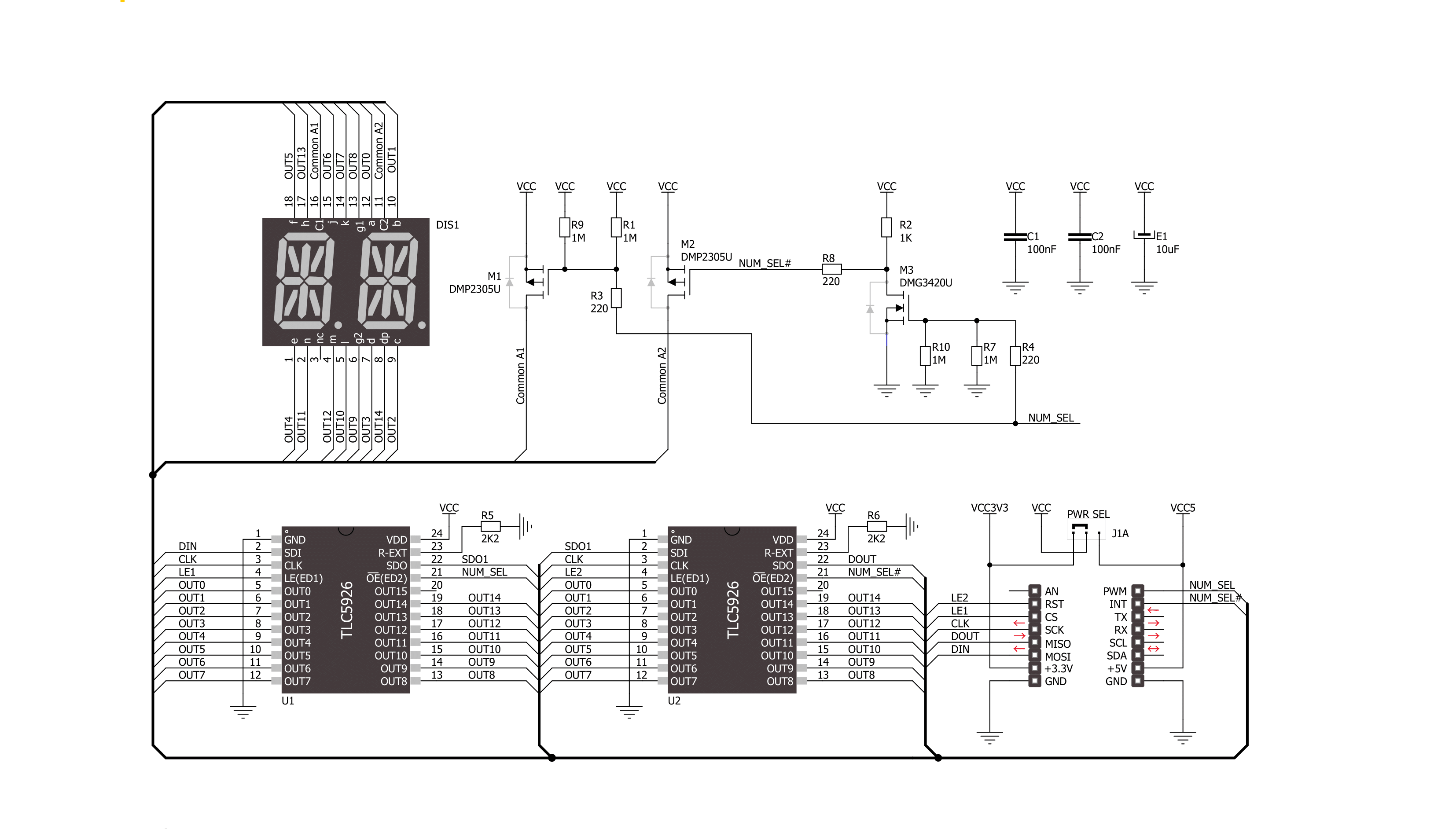
AlphaNum G Click is based on one green two digits 14-segment alphanumeric display with leading dots and two TLC5926s, 16-bit constant-current LED-sink drivers from Texas Instruments. This display consists of two sets of 14 LEDs arranged in a rectangular starburst fashion, where each of the 14 LEDs is called a segment. The segment forms part of a numerical digit (decimal and hex) or ISO basic Latin alphabet to be displayed when illuminated. The fifteenth segment of each set is a comma, suitable for displaying a decimal number. Two TLC5926s drive this display with constant currents in the sink
configuration. The TLC5926 is a 256-step programmable global current gain with constant current adjusted by an external resistor; in this case, it is kept around 8mA per segment. This Click board™ uses the SPI serial interface of the mikroBUS™ socket to communicate with the host MCU. There are four additional pins, two for each TLC5926: data latch pins marked as LE1 and LE2, routed to the CS and RST pins of the mikroBUS™ socket, and display segment select pins labeled as NS and NS# routed to the INT and PWM pins of the mikroBUS™ socket. Those latch pins are data strobe input pins where serial data is transferred to
the respective latch when they are in a high logic state. The data is latched when those pins are in a low logic state. Output enable pins are active LOW with enabled output drivers; otherwise, with a high state, the display is turned OFF. This Click board™ can operate with either 3.3V or 5V logic voltage levels selected via the PWR SEL jumper. This way, it is allowed for both 3.3V and 5V capable MCUs to use the communication lines properly. However, the Click board™ comes equipped with a library containing easy-to-use functions and an example code that can be used, as a reference, for further development.

Features overview
Development board
EasyAVR v7 is the seventh generation of AVR development boards specially designed for the needs of rapid development of embedded applications. It supports a wide range of 16-bit AVR microcontrollers from Microchip and has a broad set of unique functions, such as a powerful onboard mikroProg programmer and In-Circuit debugger over USB. The development board is well organized and designed so that the end-user has all the necessary elements in one place, such as switches, buttons, indicators, connectors, and others. With four different connectors for each port, EasyAVR v7 allows you to connect accessory boards, sensors, and custom electronics more
efficiently than ever. Each part of the EasyAVR v7 development board contains the components necessary for the most efficient operation of the same board. An integrated mikroProg, a fast USB 2.0 programmer with mikroICD hardware In-Circuit Debugger, offers many valuable programming/debugging options and seamless integration with the Mikroe software environment. Besides it also includes a clean and regulated power supply block for the development board. It can use a wide range of external power sources, including an external 12V power supply, 7-12V AC or 9-15V DC via DC connector/screw terminals, and a power source via the USB Type-B (USB-B)
connector. Communication options such as USB-UART and RS-232 are also included, alongside the well-established mikroBUS™ standard, three display options (7-segment, graphical, and character-based LCD), and several different DIP sockets which cover a wide range of 16-bit AVR MCUs. EasyAVR v7 is an integral part of the Mikroe ecosystem for rapid development. Natively supported by Mikroe software tools, it covers many aspects of prototyping and development thanks to a considerable number of different Click boards™ (over a thousand boards), the number of which is growing every day.

Microcontroller Overview
MCU Card / MCU

Architecture
AVR
MCU Memory (KB)
64
Silicon Vendor
Microchip
Pin count
40
RAM (Bytes)
4096
Used MCU Pins
mikroBUS™ mapper
Take a closer look
Click board™ Schematic
Step by step
Project assembly

Start by selecting your development board and Click board™. Begin with the EasyAVR v7 as your development board.


Software Support
Library Description
This library contains API for AlphaNum G Click driver.
Key functions:
alphanumg_write_character- This function displays characters on the left and right LED segmentsalphanumg_write_number- This function displays numbers on the left and right LED segments
Open Source
Code example
The complete application code and a ready-to-use project are available through the NECTO Studio Package Manager for direct installation in the NECTO Studio. The application code can also be found on the MIKROE GitHub account.
/*!
 * @file main.c
 * @brief AlphaNumG Click example
 *
 * # Description
 * This example showcases the initialization and configuration of the logger and Click modules
 * and shows how to display characters and numbers on both LED segments of the Click.
 *
 * The demo application is composed of two sections :
 *
 * ## Application Init
 * This function initializes and configures the logger and Click modules.
 *
 * ## Application Task
 * This function sets the time interval at which the symbols are displayed on the LED
 * segments and shows a few characters and numbers.
 *
 * @author Stefan Ilic
 *
 */

#include "board.h"
#include "log.h"
#include "alphanumg.h"

static alphanumg_t alphanumg;
static log_t logger;

void application_init ( void ) {
    log_cfg_t log_cfg;  /**< Logger config object. */
    alphanumg_cfg_t alphanumg_cfg;  /**< Click config object. */

    /**
     * Logger initialization.
     * Default baud rate: 115200
     * Default log level: LOG_LEVEL_DEBUG
     * @note If USB_UART_RX and USB_UART_TX
     * are defined as HAL_PIN_NC, you will
     * need to define them manually for log to work.
     * See @b LOG_MAP_USB_UART macro definition for detailed explanation.
     */
    LOG_MAP_USB_UART( log_cfg );
    log_init( &logger, &log_cfg );
    log_info( &logger, " Application Init " );

    // Click initialization.

    alphanumg_cfg_setup( &alphanumg_cfg );
    ALPHANUMG_MAP_MIKROBUS( alphanumg_cfg, MIKROBUS_1 );
    err_t init_flag  = alphanumg_init( &alphanumg, &alphanumg_cfg );
    if ( SPI_MASTER_ERROR == init_flag ) {
        log_error( &logger, " Application Init Error. " );
        log_info( &logger, " Please, run program again... " );

        for ( ; ; );
    }

    log_info( &logger, " Application Task " );
}

void application_task ( void ) {
    alphanumg_set_display_interval( &alphanumg, 1000 );

    alphanumg_write_character( &alphanumg, 'M', 'E' );
    alphanumg_write_character( &alphanumg, '@', '?' );

    alphanumg_write_number( &alphanumg, 0,  1 );
    alphanumg_write_number( &alphanumg, 1,  2 );
    alphanumg_write_number( &alphanumg, 2,  3 );
    alphanumg_write_number( &alphanumg, 3,  4 );
}

int main ( void )
{
    /* Do not remove this line or clock might not be set correctly. */
    #ifdef PREINIT_SUPPORTED
    preinit();
    #endif

    application_init( );

    for ( ; ; )
    {
        application_task( );
    }

    return 0;
}

// ------------------------------------------------------------------------ END
Additional Support
Resources
Category:LED Segment


