Provide real-time location-based information and interactive experiences with AK09915 and PIC32MZ1024EFH064
Discover true North

Published Sep 27, 2023
Click board™
Compass 4 Click
Dev. board
PIC32MZ clicker
Compiler
NECTO Studio
MCU
PIC32MZ1024EFH064
Achieve high-precision three-axis magnetic field measurements, allowing for accurate positioning and orientation sensing in various applications
A
A
Hardware Overview
How does it work?
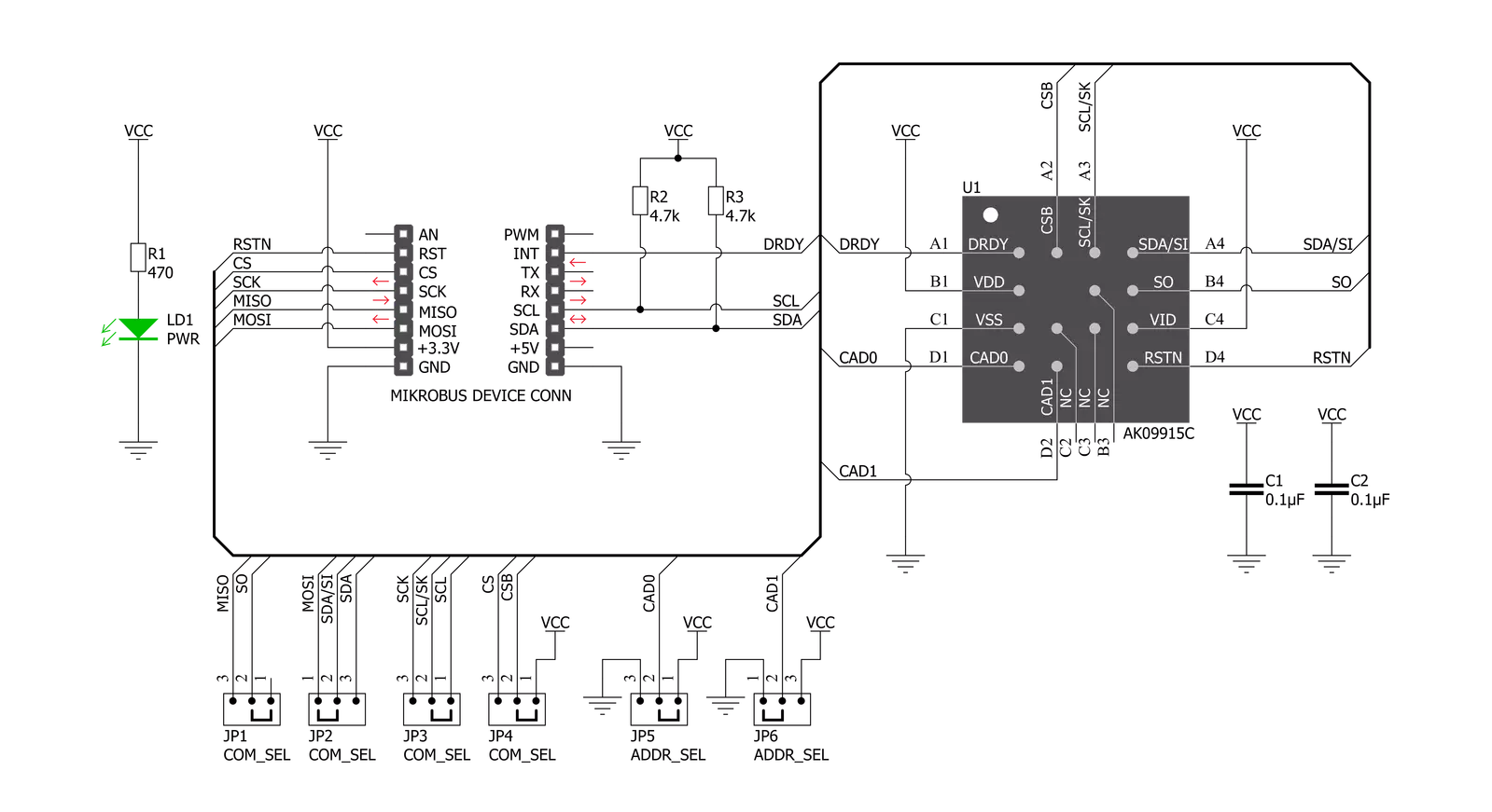
Compass 4 Click is based on the AK09915, a complete 3-axis magnetic sensor with signal processing from AKM. The AK09915 incorporates magnetic sensors for detecting terrestrial magnetism in the X-axis, Y-axis, and Z-axis, a sensor driving circuit, a signal amplifier chain, and an arithmetic circuit for processing the signal from each sensor. The output signal of each axis sensor is multiplexed, pre-amplified, processed, and digitized by a 16-bit A/D converter (ADC). A three-axis magnetometer can be programmed to measure the magnetic component for each axis within the full-scale range of ±4912 μT and sensitivity of 0.15 µT per LSB. The AK09915 has an analog circuit, digital logic, and interface block integrated into a chip. It also supports nine different Operation Modes that can be chosen by setting the appropriate registers. When the Single
Measurement Mode is set, the magnetic sensor measurement starts. After magnetic sensor measurement and signal processing are finished, measured magnetic data is stored in measurement data registers, and then the AK09915 transits to Power-Down Mode automatically. On transition to Power-Down Mode, the Data Ready (DRDY) bit turns to “1”. When any measurement data registers are read, the DRDY bit turns to “0”. It remains “1” on the transition from Power-Down Mode to another Mode. The Ready output pin of the AK09915 labeled as the DRY is routed to the INT pin of the mikroBUS™ socket. Besides the Data Ready pin, this Click board™ also has the Reset pin (RST), routed to the appropriate position on the mikroBUS™. Compass 4 Click allows for both I2C and SPI interfaces with a maximum frequency of 2.5MHz for I2C and 4MHz
for SPI communication. The selection can be performed by positioning SMD jumpers labeled COMM SEL to an appropriate position. Note that all the jumpers must be placed on the same side, or the Click board™ may become unresponsive. While the I2C interface is selected, the AK09915 allows the choice of the last two significant bits (LSB) of its I2C slave address. This can be done by using the SMD jumper labeled as ADDR SEL. Four different addresses can be set depending on the positions of each of the ADDR SEL jumpers. This Click board™ can be operated only with a 3.3V logic voltage level. The board must perform appropriate logic voltage level conversion before using MCUs with different logic levels. Also, it comes equipped with a library containing functions and an example code that can be used as a reference for further development.


Features overview
Development board
PIC32MZ Clicker is a compact starter development board that brings the flexibility of add-on Click boards™ to your favorite microcontroller, making it a perfect starter kit for implementing your ideas. It comes with an onboard 32-bit PIC32MZ microcontroller with FPU from Microchip, a USB connector, LED indicators, buttons, a mikroProg connector, and a header for interfacing with external electronics. Thanks to its compact design with clear and easy-recognizable silkscreen markings, it provides a fluid and immersive working experience, allowing access anywhere and under
any circumstances. Each part of the PIC32MZ Clicker development kit contains the components necessary for the most efficient operation of the same board. In addition to the possibility of choosing the PIC32MZ Clicker programming method, using USB HID mikroBootloader, or through an external mikroProg connector for PIC, dsPIC, or PIC32 programmer, the Clicker board also includes a clean and regulated power supply module for the development kit. The USB Micro-B connection can provide up to 500mA of current, which is more than enough to operate all onboard
and additional modules. All communication methods that mikroBUS™ itself supports are on this board, including the well-established mikroBUS™ socket, reset button, and several buttons and LED indicators. PIC32MZ Clicker is an integral part of the Mikroe ecosystem, allowing you to create a new application in minutes. Natively supported by Mikroe software tools, it covers many aspects of prototyping thanks to a considerable number of different Click boards™ (over a thousand boards), the number of which is growing every day.

Microcontroller Overview
MCU Card / MCU

Architecture
PIC32
MCU Memory (KB)
1024
Silicon Vendor
Microchip
Pin count
64
RAM (Bytes)
524288
Used MCU Pins
mikroBUS™ mapper
Take a closer look
Click board™ Schematic
Step by step
Project assembly

Start by selecting your development board and Click board™. Begin with the PIC32MZ clicker as your development board.


Software Support
Library Description
This library contains API for Compass 4 Click driver.
Key functions:
compass4_get_interrupt- Gets INT pin state (DRDY pin)compass4_get_single_axis- Gets single axis valuecompass4_get_magnetic_flux- Gets magnetic flux of X\Y\Z axis value
Open Source
Code example
The complete application code and a ready-to-use project are available through the NECTO Studio Package Manager for direct installation in the NECTO Studio. The application code can also be found on the MIKROE GitHub account.
/*!
 * \file
 * \brief Compass4 Click example
 *
 * # Description
 * This demo application measures magnetic flux data.
 *
 * The demo application is composed of two sections :
 *
 * ## Application Init
 * Initializes the driver and resets the module, then checks
 * the communication with the module and sets the module default configuration.
 *
 * ## Application Task
 * Reads magnetic flux data and displays the values of X, Y, and Z axis to
 * the USB UART each second.
 *
 * \author MikroE Team
 *
 */
// ------------------------------------------------------------------- INCLUDES

#include "board.h"
#include "log.h"
#include "compass4.h"

// ------------------------------------------------------------------ VARIABLES

static compass4_t compass4;
static log_t logger;

// ------------------------------------------------------ APPLICATION FUNCTIONS

void application_init ( void )
{
    log_cfg_t log_cfg;
    compass4_cfg_t cfg;

    uint8_t device;

    /**
     * Logger initialization.
     * Default baud rate: 115200
     * Default log level: LOG_LEVEL_DEBUG
     * @note If USB_UART_RX and USB_UART_TX
     * are defined as HAL_PIN_NC, you will
     * need to define them manually for log to work.
     * See @b LOG_MAP_USB_UART macro definition for detailed explanation.
     */
    LOG_MAP_USB_UART( log_cfg );
    log_init( &logger, &log_cfg );
    log_info( &logger, "---- Application Init ----" );

    //  Click initialization.

    compass4_cfg_setup( &cfg );
    COMPASS4_MAP_MIKROBUS( cfg, MIKROBUS_1 );
    compass4_init( &compass4, &cfg );

    compass4_hardware_reset( &compass4 );
    Delay_ms ( 500 );

    device = compass4_check_device( &compass4 );
    if ( device == 0 )
    {
        log_printf( &logger, ">> Device communication [ OK ] \r\n" );
    }
    else
    {
        log_printf( &logger, ">> Device communication [ ERROR ] \r\n" );
        for ( ; ; );
    }

    compass4_configuration ( &compass4, COMPASS4_CTRL1_WM_STEPS_5 |
                                        COMPASS4_CTRL1_NOISE_ENABLE,
                                        COMPASS4_CTRL2_MODE_CONT_1 |
                                        COMPASS4_CTRL2_SDR_LOW_NOISE |
                                        COMPASS4_CTRL2_FIFO_ENABLE );

    log_printf( &logger, ">> Start measurement  \r\n" );
}

void application_task ( void )
{
    compass4_flux_t flux;
    uint8_t err;

    err = compass4_get_magnetic_flux( &compass4, &flux );
    if ( err != 0 )
    {
        log_printf( &logger, ">> Measurement error  \r\n" );
    }
    else
    {
        log_printf( &logger, ">> Magnetic flux data << \r\n" );
        log_printf( &logger, ">> X: %.2f \r\n", flux.x );
        log_printf( &logger, ">> Y: %.2f \r\n", flux.y );
        log_printf( &logger, ">> Z: %.2f \r\n", flux.z );
    }
    log_printf( &logger, "-----------------------------\r\n" );
    Delay_ms ( 1000 );
}

int main ( void )
{
    /* Do not remove this line or clock might not be set correctly. */
    #ifdef PREINIT_SUPPORTED
    preinit();
    #endif

    application_init( );

    for ( ; ; )
    {
        application_task( );
    }

    return 0;
}

// ------------------------------------------------------------------------ END


