Direct the action of bipolar stepper motors with DRV8847 and MK64FN1M0VDC12
For single or dual brushed DC motors, one bipolar stepper motor, or solenoid loads

Published Mar 15, 2024
Click board™
Stepper 14 Click
Dev. board
Clicker 2 for Kinetis
Compiler
NECTO Studio
MCU
MK64FN1M0VDC12
Control stepper motor operation in full-, half-, quarter-, and eighth-step modes through an H-bridge configuration
A
A
Hardware Overview
How does it work?
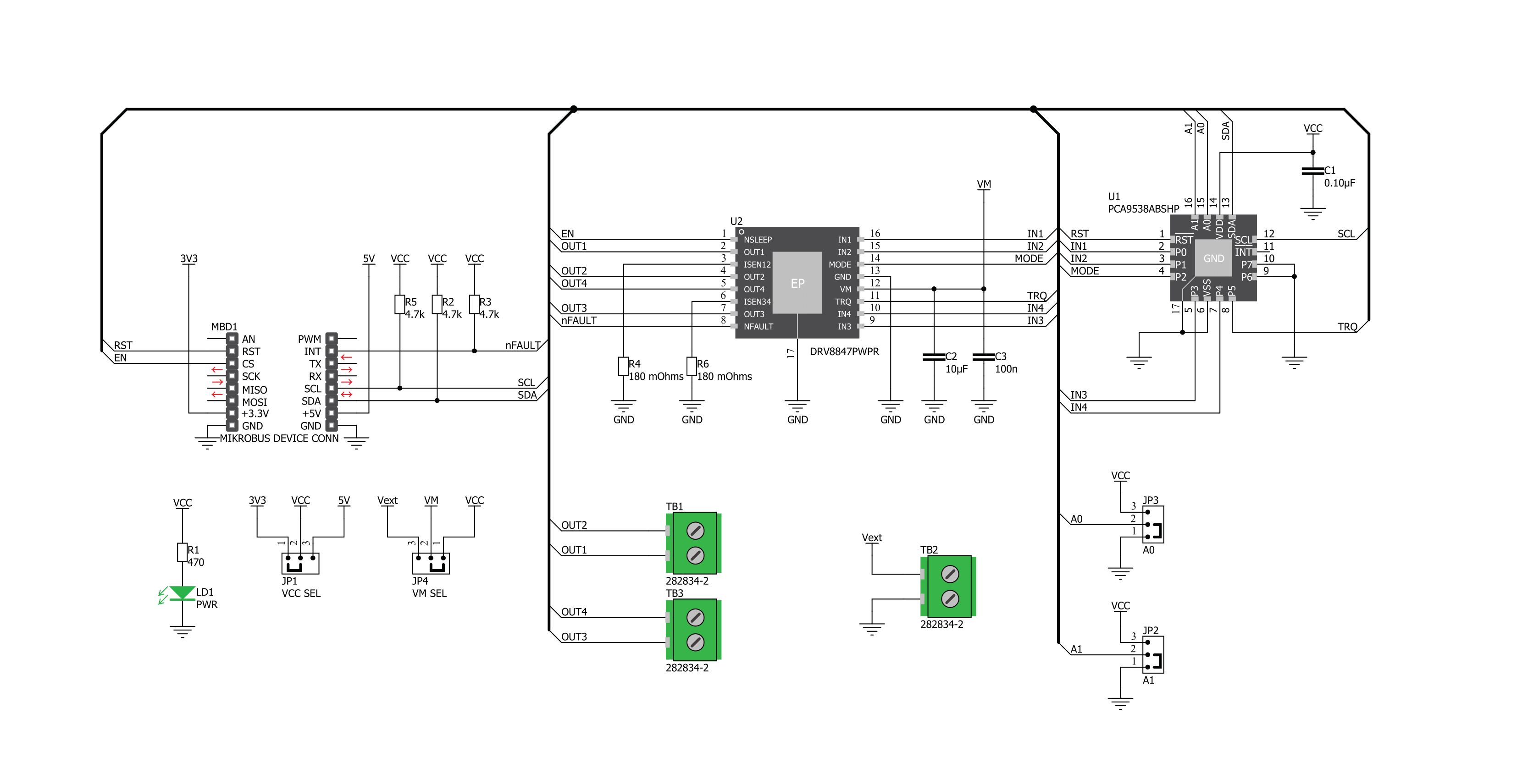
Stepper 14 Click is based on the DRV8847, a dual full-bridge motor driver from Texas Instruments. This IC's internal structure is symmetrical. It features two MOSFET H-bridges used to drive two coils of a bipolar step motor in both directions. The DRV8847 uses a wide input voltage range - from 2.7V to 18V. This is the voltage used to energize the motor coils. A jumper (JP4) is used to select whether to use an external power supply or to obtain the power supply from the mikroBUS™ +3.3V or +5V rail. The DRV8847 has two PHASE inputs, which control the direction of current flow through H-bridges and, thus, the motor coils. It also allows controlling the step motor in both full-step and half-step modes by toggling states on MS1 and MS1 pins. The bipolar step motor coils can be connected to the onboard screw terminals. There are two terminals used to connect each of the step motor coils. The third connector connects an
external voltage, ranging from 2.7V to 18V, depending on the used motor voltage requirements. It should be noted that without a valid external voltage connected to this terminal, the motor will not work. Also, it should be noted that 20V is the absolute maximum voltage allowed. Thus, the overtemperature protection might be activated when driving heavier loads. The recommended maximum voltage should not exceed 18V, as stated on the silkscreen layer of the PCB. All of the DRV8847 control lines are routed to the second IC on the Stepper 14 board, which is the PCA9538A, a well-known 8bit I/O expander with a serial interface used on many of the MikroElektronika's designs for its simplicity and reliability. It allows the control lines of the DRV8847 IC to be driven via the I2C and the few pins it uses - reducing the required pin count of the Stepper 14 click. This also allows for sending compact I2C messages instead of toggling
several pins at once - which can introduce problems with timing sometimes, especially when those pins belong to different MCU ports. Changing the states of the six control pins makes it possible to drive the step motor in full- and half-step modes. The motor power supply can be connected to the input terminal labeled as VIN and should be within the range of 2.7V to 18V. Stepper motor coils can be connected to A1, B2, B1, and A2 terminals. The Click board™ supports an optional external power supply for the motor. This Click board™ can operate with either 3.3V or 5V logic voltage levels selected via the VCC SEL jumper. This way, both 3.3V and 5V capable MCUs can use the communication lines properly. Also, this Click board™ comes equipped with a library containing easy-to-use functions and an example code that can be used as a reference for further development.

Features overview
Development board
Clicker 2 for Kinetis is a compact starter development board that brings the flexibility of add-on Click boards™ to your favorite microcontroller, making it a perfect starter kit for implementing your ideas. It comes with an onboard 32-bit ARM Cortex-M4F microcontroller, the MK64FN1M0VDC12 from NXP Semiconductors, two mikroBUS™ sockets for Click board™ connectivity, a USB connector, LED indicators, buttons, a JTAG programmer connector, and two 26-pin headers for interfacing with external electronics. Its compact design with clear and easily recognizable silkscreen markings allows you to build gadgets with unique functionalities and
features quickly. Each part of the Clicker 2 for Kinetis development kit contains the components necessary for the most efficient operation of the same board. In addition to the possibility of choosing the Clicker 2 for Kinetis programming method, using a USB HID mikroBootloader or an external mikroProg connector for Kinetis programmer, the Clicker 2 board also includes a clean and regulated power supply module for the development kit. It provides two ways of board-powering; through the USB Micro-B cable, where onboard voltage regulators provide the appropriate voltage levels to each component on the board, or
using a Li-Polymer battery via an onboard battery connector. All communication methods that mikroBUS™ itself supports are on this board, including the well-established mikroBUS™ socket, reset button, and several user-configurable buttons and LED indicators. Clicker 2 for Kinetis is an integral part of the Mikroe ecosystem, allowing you to create a new application in minutes. Natively supported by Mikroe software tools, it covers many aspects of prototyping thanks to a considerable number of different Click boards™ (over a thousand boards), the number of which is growing every day.

Microcontroller Overview
MCU Card / MCU

Architecture
ARM Cortex-M4
MCU Memory (KB)
1024
Silicon Vendor
NXP
Pin count
121
RAM (Bytes)
262144
You complete me!
Accessories
The 28BYJ-48 is an adaptable 5VDC stepper motor with a compact design, ideal for various applications. It features four phases, a speed variation ratio of 1/64, and a stride angle of 5.625°/64 steps, allowing precise control. The motor operates at a frequency of 100Hz and has a DC resistance of 50Ω ±7% at 25°C. It boasts an idle in-traction frequency greater than 600Hz and an idle out-traction frequency exceeding 1000Hz, ensuring reliability in different scenarios. With a self-positioning torque and in-traction torque both exceeding 34.3mN.m at 120Hz, the 28BYJ-48 offers robust performance. Its friction torque ranges from 600 to 1200 gf.cm, while the pull-in torque is 300 gf.cm. This motor makes a reliable and efficient choice for your stepper motor needs.

Used MCU Pins
mikroBUS™ mapper
Take a closer look
Click board™ Schematic
Step by step
Project assembly

Start by selecting your development board and Click board™. Begin with the Clicker 2 for Kinetis as your development board.


Track your results in real time
Application Output
1. Application Output - In Debug mode, the 'Application Output' window enables real-time data monitoring, offering direct insight into execution results. Ensure proper data display by configuring the environment correctly using the provided tutorial.

2. UART Terminal - Use the UART Terminal to monitor data transmission via a USB to UART converter, allowing direct communication between the Click board™ and your development system. Configure the baud rate and other serial settings according to your project's requirements to ensure proper functionality. For step-by-step setup instructions, refer to the provided tutorial.

3. Plot Output - The Plot feature offers a powerful way to visualize real-time sensor data, enabling trend analysis, debugging, and comparison of multiple data points. To set it up correctly, follow the provided tutorial, which includes a step-by-step example of using the Plot feature to display Click board™ readings. To use the Plot feature in your code, use the function: plot(*insert_graph_name*, variable_name);. This is a general format, and it is up to the user to replace 'insert_graph_name' with the actual graph name and 'variable_name' with the parameter to be displayed.

Software Support
Library Description
This library contains API for Stepper 14 Click driver.
Key functions:
stepper14_set_direction- This function sets the motor direction to clockwise or counter-clockwise in ctx->directionstepper14_set_step_mode- This function sets the step mode resolution settings in ctx->step_modestepper14_drive_motor- This function drives the motor for the specific number of steps at the selected speed
Open Source
Code example
The complete application code and a ready-to-use project are available through the NECTO Studio Package Manager for direct installation in the NECTO Studio. The application code can also be found on the MIKROE GitHub account.
/*!
 * @file main.c
 * @brief Stepper 14 Click example
 *
 * # Description
 * This example demonstrates the use of the Stepper 14 Click board by driving the
 * motor in both directions for a desired number of steps.
 *
 * The demo application is composed of two sections :
 *
 * ## Application Init
 * Initializes the driver and performs the Click default configuration.
 *
 * ## Application Task
 * Drives the motor clockwise for 200 full steps and then counter-clockwise for 400 half
 * steps with a 2 seconds delay on driving mode change. All data is being logged on the
 * USB UART where you can track the program flow.
 *
 * @author Stefan Filipovic
 *
 */

#include "board.h"
#include "log.h"
#include "stepper14.h"

static stepper14_t stepper14;
static log_t logger;

void application_init ( void )
{
    log_cfg_t log_cfg;  /**< Logger config object. */
    stepper14_cfg_t stepper14_cfg;  /**< Click config object. */

    /**
     * Logger initialization.
     * Default baud rate: 115200
     * Default log level: LOG_LEVEL_DEBUG
     * @note If USB_UART_RX and USB_UART_TX
     * are defined as HAL_PIN_NC, you will
     * need to define them manually for log to work.
     * See @b LOG_MAP_USB_UART macro definition for detailed explanation.
     */
    LOG_MAP_USB_UART( log_cfg );
    log_init( &logger, &log_cfg );
    log_info( &logger, " Application Init " );

    // Click initialization.
    stepper14_cfg_setup( &stepper14_cfg );
    STEPPER14_MAP_MIKROBUS( stepper14_cfg, MIKROBUS_1 );
    if ( I2C_MASTER_ERROR == stepper14_init( &stepper14, &stepper14_cfg ) )
    {
        log_error( &logger, " Communication init." );
        for ( ; ; );
    }

    if ( STEPPER14_ERROR == stepper14_default_cfg ( &stepper14 ) )
    {
        log_error( &logger, " Default configuration." );
        for ( ; ; );
    }

    log_info( &logger, " Application Task " );
}

void application_task ( void )
{
    log_printf ( &logger, " Move 200 full steps clockwise, speed: medium\r\n\n" );
    stepper14_set_direction ( &stepper14, STEPPER14_DIR_CW );
    stepper14_set_step_mode ( &stepper14, STEPPER14_MODE_FULL_STEP );
    stepper14_drive_motor ( &stepper14, 200, STEPPER14_SPEED_MEDIUM );
    Delay_ms ( 1000 );
    Delay_ms ( 1000 );

    log_printf ( &logger, " Move 400 half steps counter-clockwise, speed: fast\r\n\n" );
    stepper14_set_direction ( &stepper14, STEPPER14_DIR_CCW );
    stepper14_set_step_mode ( &stepper14, STEPPER14_MODE_HALF_STEP );
    stepper14_drive_motor ( &stepper14, 400, STEPPER14_SPEED_FAST );
    Delay_ms ( 1000 );
    Delay_ms ( 1000 );
}

int main ( void )
{
    /* Do not remove this line or clock might not be set correctly. */
    #ifdef PREINIT_SUPPORTED
    preinit();
    #endif

    application_init( );

    for ( ; ; )
    {
        application_task( );
    }

    return 0;
}

// ------------------------------------------------------------------------ END


