Turn your moves into tangible achievements with with LIS2DW12 and MK64FN1M0VDC12
Tri-Axis brilliance: Redefining motion tracking for the future

Published Oct 08, 2023
Click board™
Accel 10 Click
Dev. board
Clicker 2 for Kinetis
Compiler
NECTO Studio
MCU
MK64FN1M0VDC12
Our three-axis accelerometer is engineered to revolutionize motion sensing, providing accurate and real-time measurements for a multitude of applications
A
A
Hardware Overview
How does it work?
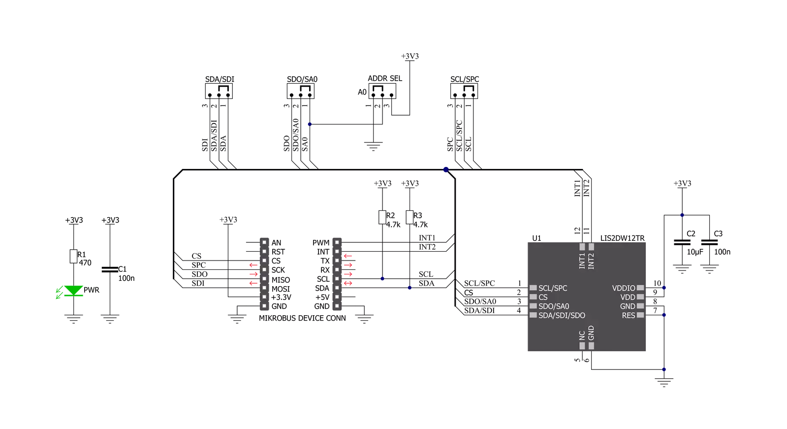
Accel 10 Click is based on the LIS2DW12TR, a high-performance ultra-low-power 3-axis "femto" accelerometer, from STMicroelectronics. This sensor has many features perfectly suited for wearables, handheld, and IoT applications, offering a good balance between the performance and the power consumption. One of its key features is its extremely low power consumption, which makes it perfectly suited for such applications. There are several power modes which the LIS2DW12TR device can use. While in Low Power mode, the device consumes only 0.38µA, but the access to some features is restricted. Having that in mind, accel 10 Click can be used for a rapid development and testing of various applications based on step counting, fitness applications, profile switching and display ON/OFF applications, angle measurement applications, and similar applications. More information can be found within the LIS2DW12TR datasheet. The LIS2DW12TR sensor can measure acceleration within ranges of ±2 g, ±4 g, ±8, and ±16 g. It can output the measurement data using the Output Data Rate (ODR) from 1.6Hz (Low Power mode), up to 1600Hz (Performance mode). A high-precision analog front end facilitates highly sensitive MEMS,
featuring a 14-bit A/D Converter. It allows very high accuracy of the output, even during very low amplitude changes. This makes the sensor particularly sensitive and accurate with movements that generate relatively low acceleration signals. However, using a highly sensitive MEMS makes the LIS2DW12TR prone to damage caused by extremely high g-forces (10,000 g for less than 200 µs). Acceleration data is available in 14-bit format from both the data registers and the internal FIFO buffer, which can can memorize 32 slots of X, Y and Z data. The FIFO buffer can be used for more complex calculations or timed readings, reducing the traffic on the communication interface. FIFO buffer allows optimization within the firmware that runs on the host MCU. Besides the acceleration MEMS and complementary analog front-end circuit, the LIS2DW12TR sensor also has an integrated temperature sensor. It is updated up to 25 times per second, and sampled to an 12-bit value (complement of 2’s format). Interrupts can be triggered for many different events. Some basic events include the data-ready interrupt event and aforementioned FIFO events, while so-called feature engines can trigger an interrupt for any of
the detected motion/movement events, including step detection/counter, activity recognition, tilt on wrist, tap/double tap, any/no motion, and error event interrupt. The extensive interrupt engine can use two programmable interrupt pins. Both of these pins can be assigned with any interrupt source and can be either LOW or HIGH on interrupt, depending on settings in appropriate registers. These two pins are routed to PWM and INT pin of the mikroBUS™, and are labeled as IT1 and IT2, respectively. Accel 10 Click offers two communication interfaces. It can be used with either I2C or SPI. The onboard SMD jumpers labeled as COMM SEL allow switching between the two interfaces. Note that all the jumpers have to be positioned either I2C or to SPI position. When I2C interface is selected, an additional SMD jumper labeled as ADDR SEL becomes available, determining the least significant bit of the LIS2DW12TR I2C address. This Click Board™ uses both I2C and SPI communication interfaces. It is designed to be operated only with 3.3V logic levels. A proper logic voltage level conversion should be performed before the Click board™ is used with MCUs with logic levels of 5V.


Features overview
Development board
Clicker 2 for Kinetis is a compact starter development board that brings the flexibility of add-on Click boards™ to your favorite microcontroller, making it a perfect starter kit for implementing your ideas. It comes with an onboard 32-bit ARM Cortex-M4F microcontroller, the MK64FN1M0VDC12 from NXP Semiconductors, two mikroBUS™ sockets for Click board™ connectivity, a USB connector, LED indicators, buttons, a JTAG programmer connector, and two 26-pin headers for interfacing with external electronics. Its compact design with clear and easily recognizable silkscreen markings allows you to build gadgets with unique functionalities and
features quickly. Each part of the Clicker 2 for Kinetis development kit contains the components necessary for the most efficient operation of the same board. In addition to the possibility of choosing the Clicker 2 for Kinetis programming method, using a USB HID mikroBootloader or an external mikroProg connector for Kinetis programmer, the Clicker 2 board also includes a clean and regulated power supply module for the development kit. It provides two ways of board-powering; through the USB Micro-B cable, where onboard voltage regulators provide the appropriate voltage levels to each component on the board, or
using a Li-Polymer battery via an onboard battery connector. All communication methods that mikroBUS™ itself supports are on this board, including the well-established mikroBUS™ socket, reset button, and several user-configurable buttons and LED indicators. Clicker 2 for Kinetis is an integral part of the Mikroe ecosystem, allowing you to create a new application in minutes. Natively supported by Mikroe software tools, it covers many aspects of prototyping thanks to a considerable number of different Click boards™ (over a thousand boards), the number of which is growing every day.

Microcontroller Overview
MCU Card / MCU

Architecture
ARM Cortex-M4
MCU Memory (KB)
1024
Silicon Vendor
NXP
Pin count
121
RAM (Bytes)
262144
Used MCU Pins
mikroBUS™ mapper
Take a closer look
Click board™ Schematic
Step by step
Project assembly

Start by selecting your development board and Click board™. Begin with the Clicker 2 for Kinetis as your development board.


Software Support
Library Description
This library contains API for Accel 10 Click driver.
Key functions:
accel10_check_data_ready- Check data ready functionaccel10_get_data- Read Accel data functionaccel10_read_temperature- Read temperature function
Open Source
Code example
The complete application code and a ready-to-use project are available through the NECTO Studio Package Manager for direct installation in the NECTO Studio. The application code can also be found on the MIKROE GitHub account.
/*!
 * \file
 * \brief Accel10 Click example
 *
 * # Description
 * This example demonstrates the use of Accel 10 Click board.
 *
 * The demo application is composed of two sections :
 *
 * ## Application Init
 * Initializes the driver and checks the communication by reading the device ID.
 * After that, performs the Click default configuration.
 *
 * ## Application Task
 * Reads the accel values for X, Y, and Z axis and also reads the temperature in Celsius
 * and displays the results on the USB UART each second.
 *
 * \author Nenad Filipovic
 *
 */
// ------------------------------------------------------------------- INCLUDES

#include "board.h"
#include "log.h"
#include "accel10.h"

// ------------------------------------------------------------------ VARIABLES

static accel10_t accel10;
static log_t logger;

static accel10_data_t accel_data;
static int8_t temperature;

// ------------------------------------------------------ APPLICATION FUNCTIONS

void application_init ( void )
{
    log_cfg_t log_cfg;
    accel10_cfg_t cfg;

    /**
     * Logger initialization.
     * Default baud rate: 115200
     * Default log level: LOG_LEVEL_DEBUG
     * @note If USB_UART_RX and USB_UART_TX
     * are defined as HAL_PIN_NC, you will
     * need to define them manually for log to work.
     * See @b LOG_MAP_USB_UART macro definition for detailed explanation.
     */
    LOG_MAP_USB_UART( log_cfg );
    log_init( &logger, &log_cfg );
    log_info( &logger, "---- Application Init ----" );

    //  Click initialization.

    accel10_cfg_setup( &cfg );
    ACCEL10_MAP_MIKROBUS( cfg, MIKROBUS_1 );
    accel10_init( &accel10, &cfg );
    Delay_ms ( 500 );

    log_printf( &logger, "---------------------\r\n" );
    log_printf( &logger, "    Accel 10 Click\r\n" );
    log_printf( &logger, "---------------------\r\n" );

    // Checking communication
    if ( accel10_check_id( &accel10 ) == ACCEL10_SUCCESS )
    {
        log_printf( &logger, "  Communication  OK\r\n" );
        log_printf( &logger, "---------------------\r\n" );
        Delay_ms ( 100 );
    }
    else
    {
        log_printf( &logger, "  Communication ERROR\r\n" );
        log_printf( &logger, "  Reset the device\r\n" );
        log_printf( &logger, "---------------------\r\n" );
        for ( ; ; );
    }

    accel10_default_cfg ( &accel10 );
    log_printf( &logger, "  Default config.\r\n" );
    log_printf( &logger, "---------------------\r\n" );
    Delay_ms ( 100 );
}

void application_task ( void )
{
    if ( accel10_check_data_ready( &accel10 ) == ACCEL10_STATUS_DATA_READY )
    {
        accel10_get_data ( &accel10, &accel_data );
        Delay_ms ( 10 );

        log_printf( &logger, "  Accel X :  %d\r\n", accel_data.x );
        log_printf( &logger, "  Accel Y :  %d\r\n", accel_data.y );
        log_printf( &logger, "  Accel Z :  %d\r\n", accel_data.z );

        temperature = accel10_read_temperature( &accel10 );
        Delay_ms ( 10 );

        log_printf( &logger, " Temperature :  %d C\r\n", ( int16_t ) temperature );
        log_printf( &logger, "---------------------\r\n" );
        Delay_ms ( 1000 );
    }
}

int main ( void )
{
    /* Do not remove this line or clock might not be set correctly. */
    #ifdef PREINIT_SUPPORTED
    preinit();
    #endif

    application_init( );

    for ( ; ; )
    {
        application_task( );
    }

    return 0;
}


// ------------------------------------------------------------------------ END


