Create responsive, energy-efficient systems that adapt to user presence and needs with PD-V11 and PIC18F46K42
From Sci-Fi to reality
Published Nov 01, 2023
Click board™
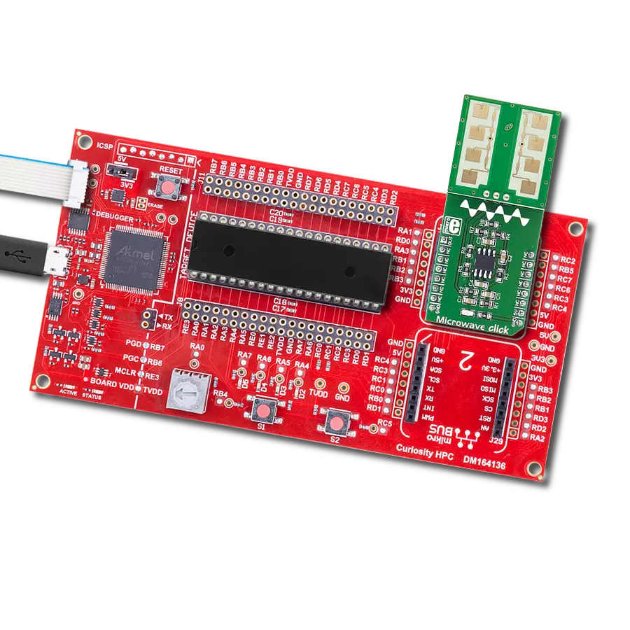
Microwave Click
Dev. board
Curiosity HPC
Compiler
NECTO Studio
MCU
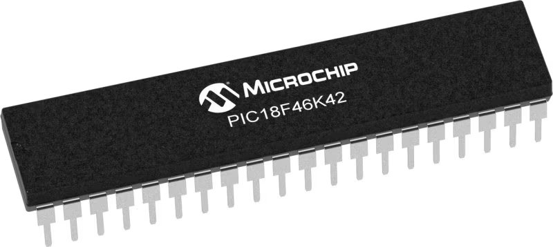
PIC18F46K42
This solution, which employs the Doppler effect with microwaves, provides the ability to detect and track motion with precision, opening doors to a wide range of applications
A
A
Hardware Overview
How does it work?
Microwave Click is based on the PD-V11, a 24GHz microwave motion sensor from Pdlux. The typical use for Microwave click is a proximity or motion detector in various applications and devices. The Microwave click can detect movement or proximity by using the Doppler effect. The onboard microwave motions sensor transmits waves, and picks them back as they hit an object, with their frequency changed. Microwave click does not need optical visibility to work, and the waves can penetrate many kinds of barriers and obstacles. Microwave click detects movement of objects utilizing Doppler effect. When the PD-V11 microwave sensor is powered on, it starts transmitting radio waves of fixed frequency. As the waves hit a moving object they are reflected back toward PD-V11 microwave motion sensor, with their frequency changed, depending on speed
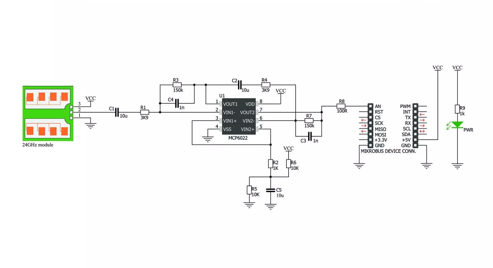
and direction of object's movement. The Doppler effect - a change in frequency of a wave for the observer and object move closer or further apart from one another. A typical example of the Doppler effect is when a vehicle with siren passes and you hear the pitch drop of the siren. The PD-V11 microwave motion sensor low power consumption, low noise, and a low wireless power output. See the datasheet to learn more. The PD-V11 microwave motion sensor picks up reflected waves and converts them to a voltage signal. This signal has the magnitude of several hundred microvolts, so it's sent to the MCP6022 which amplifies the signal, in order to make it readable over the Analog pin on the mikroBUS™. This signal is amplified up to 3.3V. Once amplified, the signal is routed to the Analog pin (OUT) on the mikroBUS™ line. The proximity of the object can
be determined by measuring the amplitude of this signal, and speed/direction by determining its frequency. The PD-V11 microwave motion sensor low power consumption, low noise, and a low wireless power output. See the datasheet to learn more. The PD-V11 microwave motion sensor picks up reflected waves and converts them to a voltage signal. This signal has the magnitude of several hundred microvolts, so it's sent to the MCP6022 which amplifies the signal, in order to make it readable over the Analog pin on the mikroBUS™. This signal is amplified up to 3.3V. Once amplified, the signal is routed to the Analog pin (OUT) on the mikroBUS™ line. The proximity of the object can be determined by measuring the amplitude of this signal, and speed/direction by determining its frequency.


Features overview
Development board
Curiosity HPC, standing for Curiosity High Pin Count (HPC) development board, supports 28- and 40-pin 8-bit PIC MCUs specially designed by Microchip for the needs of rapid development of embedded applications. This board has two unique PDIP sockets, surrounded by dual-row expansion headers, allowing connectivity to all pins on the populated PIC MCUs. It also contains a powerful onboard PICkit™ (PKOB), eliminating the need for an external programming/debugging tool, two mikroBUS™ sockets for Click board™ connectivity, a USB connector, a set of indicator LEDs, push button switches and a variable potentiometer. All
these features allow you to combine the strength of Microchip and Mikroe and create custom electronic solutions more efficiently than ever. Each part of the Curiosity HPC development board contains the components necessary for the most efficient operation of the same board. An integrated onboard PICkit™ (PKOB) allows low-voltage programming and in-circuit debugging for all supported devices. When used with the MPLAB® X Integrated Development Environment (IDE, version 3.0 or higher) or MPLAB® Xpress IDE, in-circuit debugging allows users to run, modify, and troubleshoot their custom software and hardware
quickly without the need for additional debugging tools. Besides, it includes a clean and regulated power supply block for the development board via the USB Micro-B connector, alongside all communication methods that mikroBUS™ itself supports. Curiosity HPC development board allows you to create a new application in just a few steps. Natively supported by Microchip software tools, it covers many aspects of prototyping thanks to many number of different Click boards™ (over a thousand boards), the number of which is growing daily.

Microcontroller Overview
MCU Card / MCU
Architecture
PIC
MCU Memory (KB)
64
Silicon Vendor
Microchip
Pin count
40
RAM (Bytes)
4096
Used MCU Pins
mikroBUS™ mapper
Take a closer look
Click board™ Schematic
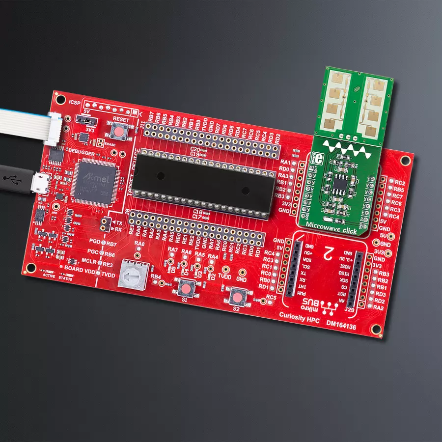
Step by step
Project assembly

Start by selecting your development board and Click board™. Begin with the Curiosity HPC as your development board.


Track your results in real time
Application Output
1. Application Output - In Debug mode, the 'Application Output' window enables real-time data monitoring, offering direct insight into execution results. Ensure proper data display by configuring the environment correctly using the provided tutorial.

2. UART Terminal - Use the UART Terminal to monitor data transmission via a USB to UART converter, allowing direct communication between the Click board™ and your development system. Configure the baud rate and other serial settings according to your project's requirements to ensure proper functionality. For step-by-step setup instructions, refer to the provided tutorial.

3. Plot Output - The Plot feature offers a powerful way to visualize real-time sensor data, enabling trend analysis, debugging, and comparison of multiple data points. To set it up correctly, follow the provided tutorial, which includes a step-by-step example of using the Plot feature to display Click board™ readings. To use the Plot feature in your code, use the function: plot(*insert_graph_name*, variable_name);. This is a general format, and it is up to the user to replace 'insert_graph_name' with the actual graph name and 'variable_name' with the parameter to be displayed.

Software Support
Library Description
This library contains API for Microwave Click driver.
Key functions:
microwave_generic_read- Generic ADC Read function
Open Source
Code example
The complete application code and a ready-to-use project are available through the NECTO Studio Package Manager for direct installation in the NECTO Studio. The application code can also be found on the MIKROE GitHub account.
/*!
* \file main.c
* \brief Microwave Click example
*
* # Description
* This is an example which demonstrates the use of Microwave Click board.
* Microwave Click reads ADC results, takes exact amount of samples,
* calculation of difference between taken samples and reference ADC value, and
* reports movement if difference is greater/lower than selected threshold value.
*
* The demo application is composed of two sections :
*
* ## Application Init
* Initializes the ADC and uart console where the results will be displayed.
* Also calculates the reference ADC value for Microwave Click board.
*
* ## Application Task
* Reads the AD converted results and compares this results with the previously
* calculated reference value, taking into account the choosen threshold value
* which controls the sensor sensitivity. All data is being displayed on the
* USB UART where you can track their changes.
*
*
* \author Nemanja Medakovic
*
*/
// ------------------------------------------------------------------- INCLUDES
#include "board.h"
#include "log.h"
#include "microwave.h"
// ------------------------------------------------------------------ VARIABLES
static microwave_t microwave;
static log_t logger;
static uint16_t reference;
static uint32_t sum;
static uint16_t old_detector = 0;
// ------------------------------------------------------ APPLICATION FUNCTIONS
void application_init( void )
{
microwave_cfg_t cfg;
log_cfg_t log_cfg;
/**
* Logger initialization.
* Default baud rate: 115200
* Default log level: LOG_LEVEL_DEBUG
* @note If USB_UART_RX and USB_UART_TX
* are defined as HAL_PIN_NC, you will
* need to define them manually for log to work.
* See @b LOG_MAP_USB_UART macro definition for detailed explanation.
*/
LOG_MAP_USB_UART( log_cfg );
log_init( &logger, &log_cfg );
log_info( &logger, "---- Application Init ----" );
// Click initialization.
microwave_cfg_setup( &cfg );
MICROWAVE_MAP_MIKROBUS( cfg, MIKROBUS_1 );
microwave_init( µwave, &cfg );
Delay_ms ( 100 );
log_printf( &logger, " Calibrating the sensor...\r\n" );
log_printf( &logger, " There must be no movement near the sensor!\r\n" );
log_printf( &logger, "*********************************************\r\n" );
Delay_ms ( 1000 );
Delay_ms ( 1000 );
Delay_ms ( 1000 );
sum = 0;
for ( uint8_t cnt = 0; cnt < MICROWAVE_SAMPLES_COUNT_100; cnt++ )
{
sum += microwave_generic_read( µwave );
}
reference = sum / MICROWAVE_SAMPLES_COUNT_100;
log_printf( &logger, " The sensor has been calibrated!\r\n" );
log_printf( &logger, "** Reference value: %d\r\n", reference );
log_printf( &logger, "*********************************************\r\n" );
Delay_ms ( 1000 );
}
void application_task( void )
{
microwave_data_t adc_sample;
uint16_t detector;
uint8_t sampler;
uint8_t cnt = 0;
sum = 0;
for ( sampler = 0; sampler < MICROWAVE_SAMPLES_COUNT_100; sampler++ )
{
adc_sample = microwave_generic_read( µwave );
sum += adc_sample;
cnt++;
}
if ( cnt )
{
detector = sum / cnt;
if ( ( ( detector + MICROWAVE_THRESHOLD_10 ) < reference ||
( detector - MICROWAVE_THRESHOLD_10 ) > reference ) &&
old_detector != detector )
{
log_printf( &logger, "** MOVE DETECTED!\r\n" );
log_printf( &logger, "** Detector value : %d\r\n", detector );
log_printf( &logger, "**************************\r\n" );
old_detector = detector;
Delay_ms ( 100 );
}
}
}
int main ( void )
{
/* Do not remove this line or clock might not be set correctly. */
#ifdef PREINIT_SUPPORTED
preinit();
#endif
application_init( );
for ( ; ; )
{
application_task( );
}
return 0;
}
// ------------------------------------------------------------------------ END
Additional Support
Resources
Category:Motion


