Create a secure connection to IoT ExpressLink services with SARA-R510AWS and PIC18F4685
Uninterrupted connectivity for smart devices, today and tomorrow
Published Nov 01, 2023
Click board™
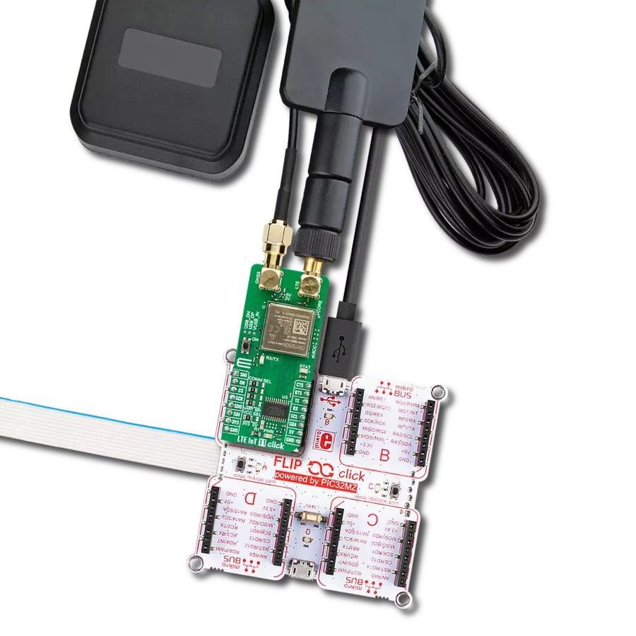
IoT ExpressLink 2 Click
Dev. board
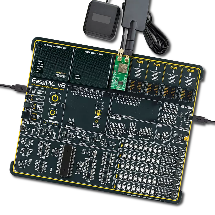
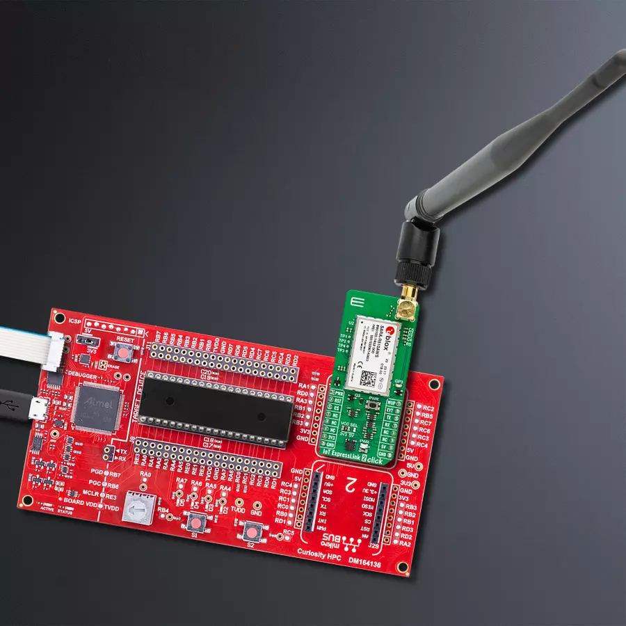
Curiosity HPC
Compiler
NECTO Studio
MCU
PIC18F4685
Powerful and versatile tool for IoT development, offering advanced features, secure connectivity, and future-proofing through 5G readiness
A
A
Hardware Overview
How does it work?
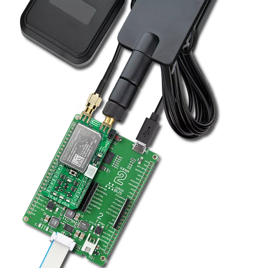
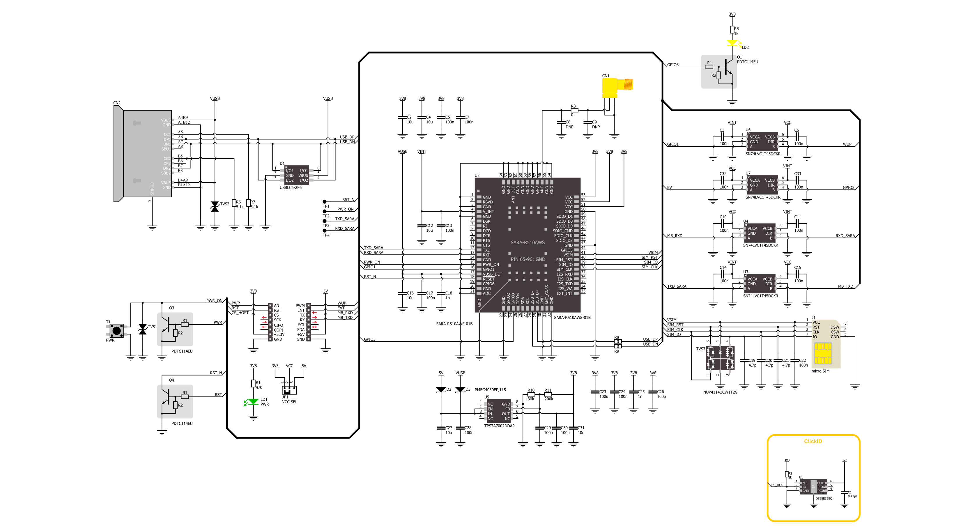
IoT ExpressLink 2 Click is based on the SARA-R510AWS, an LTE-M AWS IoT EsxpressLink module from Trasna. The embedded AWS IoT ExpressLink certified software provides a new tailored AT command set that paves the way to AWS cloud access straight out of the box, significantly accelerating time-to-market. It features direct AWS IoT cloud access secured with a hardware-based root of trust, secure boot, uFOTA, FOAT, host OTA, ultra-low sleep, and more. The module provides access to an AWS service without requiring the user to integrate any additional API on the host MCU. Every single step is handled inside the module. The module features TCP/IP, MQTT, and TLS/DTLS protocols. Some Trasna-supported compatible services are CellLocate and Zero Touch Provisioning for AWS IoT ExpressLink. By using Cat M1 half-duplex, it can achieve 375kbit/s DL and 1200 kbit/s UL. The module possesses the SMA antenna connector, which can
connect the appropriate antenna for improved range and received signal strength. The Micro SIM card holder on the back of the Click board™ is used to install a micro-SIM card. This device cannot be used without a valid SIM card, which allows connection to the cellular network. Both 1.8V and 3V (U)SIM card types are supported. Onboard, a PWR key allows you to power on the device. There are four test pads for testing purposes. One is the Power On, while the rest are reset, TXD, and RXD of the Sara module. There is a yellow LED that represents the asynchronous event flag. The module supports a high-speed USB 2.0 compliant interface available over the USB C connector. The USB interface supports a maximum of 480Mbit/s of data rate. The module itself acts as a USB device and can be connected to any USB host. The USB interface is available for diagnostic purposes only. The module can be powered over the USB C connector or the 5V of
the mikroBUS™ socket. It uses the TPS7A7002 for voltage regulation, a very low input and dropout 3A regulator from Texas Instruments. IoT ExpressLink 2 Click uses a standard 2-Wire USRT interface to communicate with the host MCU, with a fixed 115200kbps baud rate. Besides the onboard PWR key, you can power the device over the PWR pin. The WUP pin is configured as a low-power sleep state wakeup pin. The RST is for resetting the device. Also, besides the mentioned yellow LED, the event flags can be monitored over the EVT pin. This Click board™ can operate with either 3.3V or 5V logic voltage levels selected via the VCC SEL jumper. This way, both 3.3V and 5V capable MCUs can use the communication lines properly. Also, this Click board™ comes equipped with a library containing easy-to-use functions and an example code that can be used as a reference for further development.

Features overview
Development board
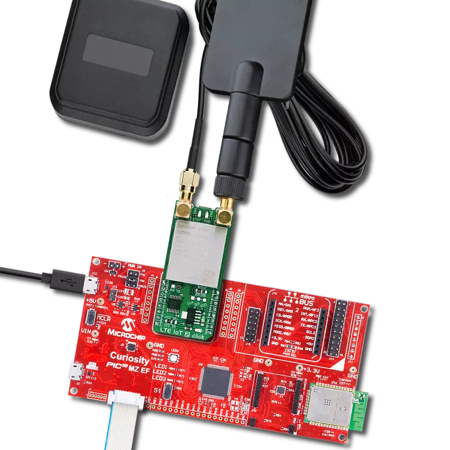
Curiosity HPC, standing for Curiosity High Pin Count (HPC) development board, supports 28- and 40-pin 8-bit PIC MCUs specially designed by Microchip for the needs of rapid development of embedded applications. This board has two unique PDIP sockets, surrounded by dual-row expansion headers, allowing connectivity to all pins on the populated PIC MCUs. It also contains a powerful onboard PICkit™ (PKOB), eliminating the need for an external programming/debugging tool, two mikroBUS™ sockets for Click board™ connectivity, a USB connector, a set of indicator LEDs, push button switches and a variable potentiometer. All
these features allow you to combine the strength of Microchip and Mikroe and create custom electronic solutions more efficiently than ever. Each part of the Curiosity HPC development board contains the components necessary for the most efficient operation of the same board. An integrated onboard PICkit™ (PKOB) allows low-voltage programming and in-circuit debugging for all supported devices. When used with the MPLAB® X Integrated Development Environment (IDE, version 3.0 or higher) or MPLAB® Xpress IDE, in-circuit debugging allows users to run, modify, and troubleshoot their custom software and hardware
quickly without the need for additional debugging tools. Besides, it includes a clean and regulated power supply block for the development board via the USB Micro-B connector, alongside all communication methods that mikroBUS™ itself supports. Curiosity HPC development board allows you to create a new application in just a few steps. Natively supported by Microchip software tools, it covers many aspects of prototyping thanks to many number of different Click boards™ (over a thousand boards), the number of which is growing daily.

Microcontroller Overview
MCU Card / MCU
Architecture
PIC
MCU Memory (KB)
96
Silicon Vendor
Microchip
Pin count
40
RAM (Bytes)
3328
You complete me!
Accessories
This multiband LTE Rubber Antenna with adjustable angle is an excellent choice for all 3G/4G LTE-based click boards from our offer, as well as other devices that require excellent throughput on all major cellular bands worldwide. The antenna has an SMA male connector, which allows it to be mounted directly on the Click board™ or the female SMA module connector. The antenna position can be adjusted in 45⁰ increments (0⁰/45⁰/90⁰).

Used MCU Pins
mikroBUS™ mapper
Take a closer look
Click board™ Schematic
Step by step
Project assembly

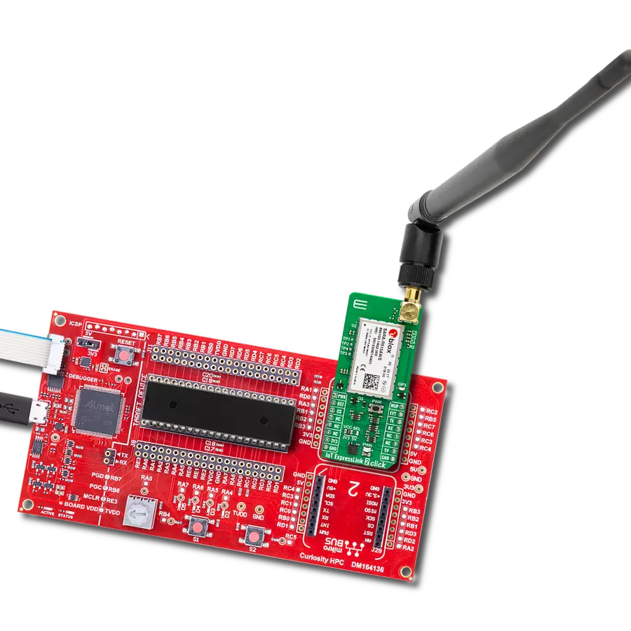
Start by selecting your development board and Click board™. Begin with the Curiosity HPC as your development board.


Track your results in real time
Application Output
1. Application Output - In Debug mode, the 'Application Output' window enables real-time data monitoring, offering direct insight into execution results. Ensure proper data display by configuring the environment correctly using the provided tutorial.

2. UART Terminal - Use the UART Terminal to monitor data transmission via a USB to UART converter, allowing direct communication between the Click board™ and your development system. Configure the baud rate and other serial settings according to your project's requirements to ensure proper functionality. For step-by-step setup instructions, refer to the provided tutorial.

3. Plot Output - The Plot feature offers a powerful way to visualize real-time sensor data, enabling trend analysis, debugging, and comparison of multiple data points. To set it up correctly, follow the provided tutorial, which includes a step-by-step example of using the Plot feature to display Click board™ readings. To use the Plot feature in your code, use the function: plot(*insert_graph_name*, variable_name);. This is a general format, and it is up to the user to replace 'insert_graph_name' with the actual graph name and 'variable_name' with the parameter to be displayed.

Software Support
Library Description
This library contains API for IoT ExpressLink 2 Click driver.
Key functions:
iotexpresslink2_power_on- This function performs the power on sequence.iotexpresslink2_send_cmd- This function send command string by using UART serial interface.iotexpresslink2_generic_read- This function reads a desired number of data bytes by using UART serial interface.
Open Source
Code example
The complete application code and a ready-to-use project are available through the NECTO Studio Package Manager for direct installation in the NECTO Studio. The application code can also be found on the MIKROE GitHub account.
/*!
 * @file main.c
 * @brief IoT ExpressLink 2 Click Example.
 *
 * # Description
 * This example demonstrates the use of IoT ExpressLink 2 Click board by connecting
 * to the selected AWS account's data endpoint and showcasing the messaging topic model
 * through sending and receiving messages to/from AWS IoT console.
 *
 * The demo application is composed of two sections :
 *
 * ## Application Init
 * Initializes the driver and logger, powers up the device, reads and displays
 * the vendor model, thing name, and the PEM certificate of the device. It then sets
 * the SIM APN and device endpoint, and attempts to connect to AWS network.
 * Finally, it configures the topic name and number and subscribes to it.
 *
 * ## Application Task
 * Sends a desired message on the configured topic and retrieves the next two pending
 * messages from the same topic approximately every 10 seconds. The sent message is also
 * added to the receive queue because the same topic is used for both sending and receiving.
 *
 * ## Additional Function
 * - static void iotexpresslink2_clear_app_buf ( void )
 * - static err_t iotexpresslink2_process ( iotexpresslink2_t *ctx )
 * - static err_t iotexpresslink2_read_response ( iotexpresslink2_t *ctx, uint32_t timeout )
 *
 * @note
 * Steps for the very first connection attempt:
 *  1. During the initial connection attempt, the device responds with: "ERR14 UNABLE TO CONNECT
 * Certificate generation completed. Proceed to register device with AWS cloud and then try
 * to connect again".
 *  2. At this point, you should restart the system and proceed with registering the device
 * with the AWS Cloud using device's thing name and PEM certificate displayed in the logger.
 * Detailed steps for registering device are described in the module's application development guide.
 *  3. After registering the device with your AWS account, restart the system, and it should
 * now successfully connect to the cloud.
 *
 * @author Stefan Filipovic
 *
 */

#include "board.h"
#include "log.h"
#include "iotexpresslink2.h"

// Enter valid APN below for inserted SIM card
#define SIM_APN                 "internet"

// Enter the device data endpoint below for your AWS account in form:
// xxxxxxxxxxxxxx-ats.iot.us-east-1.amazonaws.com
#define DEVICE_ENDPOINT         ""

// Device topic and text message
#define TOPIC_NUM               "1"
#define TOPIC_NAME              "IoT_ExpressLink_2"
#define TEXT_MESSAGE            "IoT ExpressLink 2 Click board - demo message"

// Application buffer size
#define APP_BUFFER_SIZE         900
#define PROCESS_BUFFER_SIZE     100

static iotexpresslink2_t iotexpresslink2;
static log_t logger;

static uint8_t app_buf[ APP_BUFFER_SIZE ] = { 0 };
static int32_t app_buf_len = 0;

/**
 * @brief IoT ExpressLink 2 clearing application buffer.
 * @details This function clears memory of application buffer and reset its length.
 * @note None.
 */
static void iotexpresslink2_clear_app_buf ( void );

/**
 * @brief IoT ExpressLink 2 data reading function.
 * @details This function reads data from device and concatenates data to application buffer.
 * @param[in] ctx : Click context object.
 * See #iotexpresslink2_t object definition for detailed explanation.
 * @return @li @c  0 - Read some data.
 *         @li @c -1 - Nothing is read.
 * See #err_t definition for detailed explanation.
 * @note None.
 */
static err_t iotexpresslink2_process ( iotexpresslink2_t *ctx );

/**
 * @brief IoT ExpressLink read response function.
 * @details This function waits for a response message, reads and displays it on the USB UART.
 * @param[in] ctx : Click context object.
 * See #iotexpresslink_t object definition for detailed explanation.
 * @param[in] timeout : Timeout for command response in milliseconds.
 * @return @li @c  0 - OK response.
 *         @li @c -1 - Unknown error.
 *         @li @c -2 - Timeout error.
 *         @li @c -3 - Command error.
 * See #err_t definition for detailed explanation.
 * @note None.
 */
static err_t iotexpresslink2_read_response ( iotexpresslink2_t *ctx, uint32_t timeout );

void application_init ( void )
{
    log_cfg_t log_cfg;  /**< Logger config object. */
    iotexpresslink2_cfg_t iotexpresslink2_cfg;  /**< Click config object. */

    /**
     * Logger initialization.
     * Default baud rate: 115200
     * Default log level: LOG_LEVEL_DEBUG
     * @note If USB_UART_RX and USB_UART_TX
     * are defined as HAL_PIN_NC, you will
     * need to define them manually for log to work.
     * See @b LOG_MAP_USB_UART macro definition for detailed explanation.
     */
    LOG_MAP_USB_UART( log_cfg );
    log_init( &logger, &log_cfg );
    log_info( &logger, " Application Init " );

    // Click initialization.
    iotexpresslink2_cfg_setup( &iotexpresslink2_cfg );
    IOTEXPRESSLINK2_MAP_MIKROBUS( iotexpresslink2_cfg, MIKROBUS_1 );
    if ( UART_ERROR == iotexpresslink2_init( &iotexpresslink2, &iotexpresslink2_cfg ) )
    {
        log_error( &logger, " Communication init." );
        for ( ; ; );
    }
    log_printf( &logger, "Power up device\r\n\n" );
    iotexpresslink2_power_on ( &iotexpresslink2 );

    log_printf( &logger, "Get vendor model\r\n" );
    strcpy ( app_buf, IOTEXPRESSLINK2_CMD_CONF_CHECK );
    strcat ( app_buf, IOTEXPRESSLINK2_CMD_SEPARATOR );
    strcat ( app_buf, IOTEXPRESSLINK2_CONF_KEY_ABOUT );
    iotexpresslink2_send_cmd ( &iotexpresslink2, app_buf );
    iotexpresslink2_read_response ( &iotexpresslink2, IOTEXPRESSLINK2_NORMAL_TIMEOUT );

    log_printf( &logger, "Get thing name\r\n" );
    strcpy ( app_buf, IOTEXPRESSLINK2_CMD_CONF_CHECK );
    strcat ( app_buf, IOTEXPRESSLINK2_CMD_SEPARATOR );
    strcat ( app_buf, IOTEXPRESSLINK2_CONF_KEY_THING_NAME );
    iotexpresslink2_send_cmd ( &iotexpresslink2, app_buf );
    iotexpresslink2_read_response ( &iotexpresslink2, IOTEXPRESSLINK2_NORMAL_TIMEOUT );

    log_printf( &logger, "Get certificate pem\r\n" );
    strcpy ( app_buf, IOTEXPRESSLINK2_CMD_CONF_CHECK );
    strcat ( app_buf, IOTEXPRESSLINK2_CMD_SEPARATOR );
    strcat ( app_buf, IOTEXPRESSLINK2_CONF_KEY_CERTIFICATE_PEM );
    iotexpresslink2_send_cmd ( &iotexpresslink2, app_buf );
    iotexpresslink2_read_response ( &iotexpresslink2, IOTEXPRESSLINK2_NORMAL_TIMEOUT );

    log_printf( &logger, "Set SIM APN to: %s\r\n", ( char * ) SIM_APN );
    strcpy ( app_buf, IOTEXPRESSLINK2_CMD_CONF );
    strcat ( app_buf, IOTEXPRESSLINK2_CMD_SEPARATOR );
    strcat ( app_buf, IOTEXPRESSLINK2_CONF_KEY_APN );
    strcat ( app_buf, IOTEXPRESSLINK2_CMD_SIGN_EQUAL );
    strcat ( app_buf, SIM_APN );
    iotexpresslink2_send_cmd ( &iotexpresslink2, app_buf );
    iotexpresslink2_read_response ( &iotexpresslink2, IOTEXPRESSLINK2_NORMAL_TIMEOUT );

    log_printf( &logger, "Set device endpoint to: %s\r\n", ( char * ) DEVICE_ENDPOINT );
    strcpy ( app_buf, IOTEXPRESSLINK2_CMD_CONF );
    strcat ( app_buf, IOTEXPRESSLINK2_CMD_SEPARATOR );
    strcat ( app_buf, IOTEXPRESSLINK2_CONF_KEY_ENDPOINT );
    strcat ( app_buf, IOTEXPRESSLINK2_CMD_SIGN_EQUAL );
    strcat ( app_buf, DEVICE_ENDPOINT );
    iotexpresslink2_send_cmd ( &iotexpresslink2, app_buf );
    iotexpresslink2_read_response ( &iotexpresslink2, IOTEXPRESSLINK2_NORMAL_TIMEOUT );

    log_printf( &logger, "Trying to connect...\r\n" );
    log_printf( &logger, "This may take up to 15min for the initial connect.\r\n" );
    iotexpresslink2_send_cmd ( &iotexpresslink2, IOTEXPRESSLINK2_CMD_CONNECT );
    if ( IOTEXPRESSLINK2_OK !=
         iotexpresslink2_read_response ( &iotexpresslink2, IOTEXPRESSLINK2_CONNECT_TIMEOUT ) )
    {
        log_printf( &logger, "\r\nUNABLE TO CONNECT\r\n" );
        log_printf( &logger, "Make sure that the SIM card is inserted in the board, \r\n" );
        log_printf( &logger, "an antenna is connected, and the module is within range \r\n" );
        log_printf( &logger, "of a cellular network that provides LTE-M coverage.\r\n" );
        log_printf( &logger, "Double check that the device registration procedure have been \r\n" );
        log_printf( &logger, "correctly followed. If CONNECT worked in the past for this \r\n" );
        log_printf( &logger, "device, it may be that the cellular network has decided \r\n" );
        log_printf( &logger, "to refuse service for a \"guard time\" (e.g. 1 hour) because \r\n" );
        log_printf( &logger, "the device has connected and disconnected more than a handful \r\n" );
        log_printf( &logger, "of times in quick succession. The only way to avoid this is \r\n" );
        log_printf( &logger, "avoiding many connections/disconnections. \r\n" );
        for ( ; ; );
    }

    log_printf( &logger, "Set topic %s to: %s\r\n", ( char * ) TOPIC_NUM, ( char * ) TOPIC_NAME );
    strcpy ( app_buf, IOTEXPRESSLINK2_CMD_CONF );
    strcat ( app_buf, IOTEXPRESSLINK2_CMD_SEPARATOR );
    strcat ( app_buf, IOTEXPRESSLINK2_CONF_KEY_TOPIC );
    strcat ( app_buf, TOPIC_NUM );
    strcat ( app_buf, IOTEXPRESSLINK2_CMD_SIGN_EQUAL );
    strcat ( app_buf, TOPIC_NAME );
    iotexpresslink2_send_cmd ( &iotexpresslink2, app_buf );
    iotexpresslink2_read_response ( &iotexpresslink2, IOTEXPRESSLINK2_NORMAL_TIMEOUT );

    log_printf( &logger, "Subscribe to topic %s\r\n", ( char * ) TOPIC_NUM );
    strcpy ( app_buf, IOTEXPRESSLINK2_CMD_SUBSCRIBE );
    strcat ( app_buf, TOPIC_NUM );
    iotexpresslink2_send_cmd ( &iotexpresslink2, app_buf );
    iotexpresslink2_read_response ( &iotexpresslink2, IOTEXPRESSLINK2_NORMAL_TIMEOUT );

    log_info( &logger, " Application Task " );
}

void application_task ( void )
{
    // Send message on topic
    log_printf( &logger, "Send message on topic: %s\r\n", ( char * ) TOPIC_NAME );
    strcpy ( app_buf, IOTEXPRESSLINK2_CMD_SEND );
    strcat ( app_buf, TOPIC_NUM );
    strcat ( app_buf, IOTEXPRESSLINK2_CMD_SEPARATOR );
    strcat ( app_buf, TEXT_MESSAGE );
    iotexpresslink2_send_cmd ( &iotexpresslink2, app_buf );
    iotexpresslink2_read_response ( &iotexpresslink2, IOTEXPRESSLINK2_NORMAL_TIMEOUT );
    Delay_ms ( 1000 );

    // Retrieve the next message received on topic in the order of arrival.
    log_printf( &logger, "Request next message pending on topic: %s\r\n", ( char * ) TOPIC_NAME );
    strcpy ( app_buf, IOTEXPRESSLINK2_CMD_GET );
    strcat ( app_buf, TOPIC_NUM );
    iotexpresslink2_send_cmd ( &iotexpresslink2, app_buf );
    iotexpresslink2_read_response ( &iotexpresslink2, IOTEXPRESSLINK2_NORMAL_TIMEOUT );
    // 8 seconds delay
    Delay_ms ( 1000 );
    Delay_ms ( 1000 );
    Delay_ms ( 1000 );
    Delay_ms ( 1000 );
    Delay_ms ( 1000 );
    Delay_ms ( 1000 );
    Delay_ms ( 1000 );
    Delay_ms ( 1000 );
}

int main ( void )
{
    /* Do not remove this line or clock might not be set correctly. */
    #ifdef PREINIT_SUPPORTED
    preinit();
    #endif

    application_init( );

    for ( ; ; )
    {
        application_task( );
    }

    return 0;
}

static void iotexpresslink2_clear_app_buf ( void )
{
    memset( app_buf, 0, APP_BUFFER_SIZE );
    app_buf_len = 0;
}

static void iotexpresslink2_log_app_buf ( void )
{
    for ( int32_t buf_cnt = 0; buf_cnt < app_buf_len; buf_cnt++ )
    {
        log_printf( &logger, "%c", app_buf[ buf_cnt ] );
    }
}

static err_t iotexpresslink2_process ( iotexpresslink2_t *ctx )
{
    uint8_t rx_buf[ PROCESS_BUFFER_SIZE ] = { 0 };
    int32_t overflow_bytes = 0;
    int32_t rx_cnt = 0;
    int32_t rx_size = iotexpresslink2_generic_read( ctx, rx_buf, PROCESS_BUFFER_SIZE );
    if ( ( rx_size > 0 ) && ( rx_size <= APP_BUFFER_SIZE ) )
    {
        if ( ( app_buf_len + rx_size ) > APP_BUFFER_SIZE )
        {
            overflow_bytes = ( app_buf_len + rx_size ) - APP_BUFFER_SIZE;
            app_buf_len = APP_BUFFER_SIZE - rx_size;
            memmove ( app_buf, &app_buf[ overflow_bytes ], app_buf_len );
            memset ( &app_buf[ app_buf_len ], 0, overflow_bytes );
        }
        for ( rx_cnt = 0; rx_cnt < rx_size; rx_cnt++ )
        {
            if ( rx_buf[ rx_cnt ] )
            {
                app_buf[ app_buf_len++ ] = rx_buf[ rx_cnt ];
            }
        }
        return IOTEXPRESSLINK2_OK;
    }
    return IOTEXPRESSLINK2_ERROR;
}

static err_t iotexpresslink2_read_response ( iotexpresslink2_t *ctx, uint32_t timeout )
{
    uint32_t timeout_cnt = 0;
    iotexpresslink2_clear_app_buf ( );
    iotexpresslink2_process( ctx );
    while ( ( 0 == strstr( app_buf, IOTEXPRESSLINK2_RSP_OK ) ) &&
            ( 0 == strstr( app_buf, IOTEXPRESSLINK2_RSP_ERR ) ) )
    {
        iotexpresslink2_process( ctx );
        if ( timeout_cnt++ > timeout )
        {
            iotexpresslink2_clear_app_buf( );
            return IOTEXPRESSLINK2_ERROR_TIMEOUT;
        }
        Delay_ms ( 1 );
    }
    Delay_ms ( 100 );
    while ( IOTEXPRESSLINK2_OK == iotexpresslink2_process( ctx ) )
    {
        Delay_ms ( 100 );
    }
    if ( app_buf_len > 0 )
    {
        log_printf( &logger, "%s\r\n", app_buf );
    }
    Delay_ms ( 100 );
    if ( strstr( app_buf, IOTEXPRESSLINK2_RSP_OK ) )
    {
        iotexpresslink2_clear_app_buf( );
        return IOTEXPRESSLINK2_OK;
    }
    else if ( strstr( app_buf, IOTEXPRESSLINK2_RSP_ERR ) )
    {
        iotexpresslink2_clear_app_buf( );
        return IOTEXPRESSLINK2_ERROR_CMD;
    }
    iotexpresslink2_clear_app_buf( );
    return IOTEXPRESSLINK2_ERROR;
}

// ------------------------------------------------------------------------ END