Adapt to varying communication needs with ease using RN2483 and PIC32MZ2048EFH100
433/868MHz: The frequency of choice for reliable, long-distance connectivity

Published Nov 09, 2023
Click board™
LR Click
Dev. board
Flip&Click PIC32MZ
Compiler
NECTO Studio
MCU
PIC32MZ2048EFH100
Maximize your network's capabilities with our 433/868MHz long-range transceiver, ensuring your data transmission remains dependable and efficient, even in remote or harsh conditions.
A
A
Hardware Overview
How does it work?
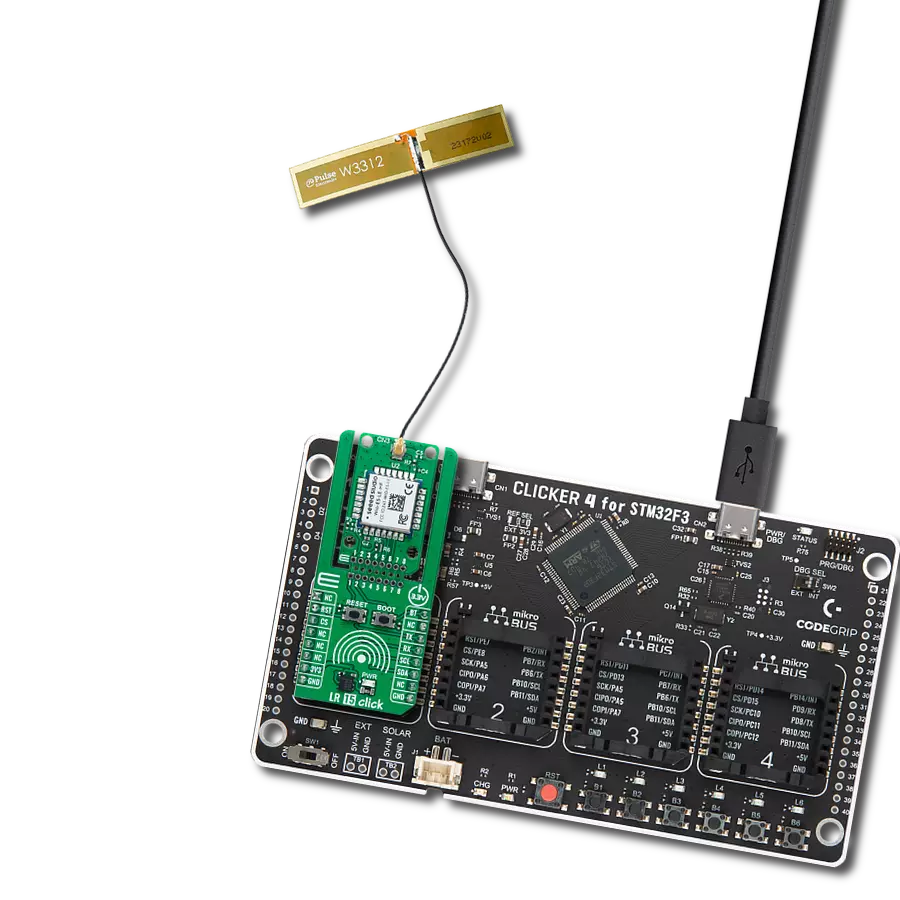
LR Click is based on the RN2483, a low-power, long-range RF technology-based transceiver module from Microchip. It features the Class A LoRaWAN compliant stack, optimized for robust LoRaWAN networking, immune to interferences, and suitable for long-range wireless operation. It offers a long-range spread spectrum communication with high interference immunity. A receiver with a sensitivity of -148dBm combined with the 14dBm integrated amplifier allows for extended range links that can achieve up to 15km in an open area (by the module manufacturer specification). This Click board™ offers data rates of 300kbps with FSK modulation and 5468bps with LoRa Technology modulation. To join a LoRaWAN network, the RN2483 requires a LoRaWAN concentrator/gateway. The endpoint device has to use a unique endpoint address, an application session key, and a network session key. The first method is called over-the-air activation
(OTAA), where these keys are issued after a specific join procedure. The second method is to assign these keys manually, using UART commands. This method is called activation by personalization (ABP) and can be prone to some security issues. In any case, before an end device can communicate on the LoRaWAN network, it must be activated. LR Click communicates with MCU using the UART interface with commonly used UART RX and TX pins, including the hardware flow control pins CTS and RTS (Clear to Send, Ready to Send) at data rates up to 57600bps for the data transfer. There are three groups of commands used to configure and operate the separate layers of the RN2483 (SYSTEM, MAC, and RADIO). Each layer controls a specific area of the module, and every UART command starts with one of the three keywords, which represent an abbreviation of the layer name they are controlling. The module also has a non-volatile memory (EEPROM) for storing the
configuration settings and some additional data. Also, this Click board™ can be reset through the Hardware Reset pin, labeled as RST on the mikroBUS™ socket, by setting this pin to a low logic state. This LR module integrates a very flexible transceiver, offering a choice of two communication frequencies that can be used, 868MHz and 433MHz. Also, it possesses two SMA antenna connectors with an impedance of 50Ω for connecting the appropriate antenna that MIKROE offers. This Click board™ can operate with either 3.3V or 5V logic voltage levels selected via the VCC SEL jumper. This way, both 3.3V and 5V capable MCUs can use the communication lines properly. Also, this Click board™ comes equipped with a library containing easy-to-use functions and an example code that can be used as a reference for further development.

Features overview
Development board
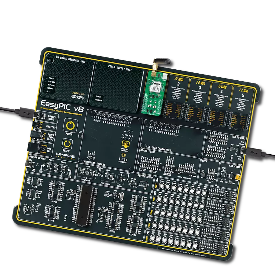
Flip&Click PIC32MZ is a compact development board designed as a complete solution that brings the flexibility of add-on Click boards™ to your favorite microcontroller, making it a perfect starter kit for implementing your ideas. It comes with an onboard 32-bit PIC32MZ microcontroller, the PIC32MZ2048EFH100 from Microchip, four mikroBUS™ sockets for Click board™ connectivity, two USB connectors, LED indicators, buttons, debugger/programmer connectors, and two headers compatible with Arduino-UNO pinout. Thanks to innovative manufacturing technology,
it allows you to build gadgets with unique functionalities and features quickly. Each part of the Flip&Click PIC32MZ development kit contains the components necessary for the most efficient operation of the same board. In addition, there is the possibility of choosing the Flip&Click PIC32MZ programming method, using the chipKIT bootloader (Arduino-style development environment) or our USB HID bootloader using mikroC, mikroBasic, and mikroPascal for PIC32. This kit includes a clean and regulated power supply block through the USB Type-C (USB-C) connector. All communication
methods that mikroBUS™ itself supports are on this board, including the well-established mikroBUS™ socket, user-configurable buttons, and LED indicators. Flip&Click PIC32MZ development kit allows you to create a new application in minutes. Natively supported by Mikroe software tools, it covers many aspects of prototyping thanks to a considerable number of different Click boards™ (over a thousand boards), the number of which is growing every day.

Microcontroller Overview
MCU Card / MCU

Architecture
PIC32
MCU Memory (KB)
2048
Silicon Vendor
Microchip
Pin count
100
RAM (Bytes)
524288
You complete me!
Accessories
Right angle 433MHz rubber antenna boasts a frequency range of 433MHz, ensuring optimal performance within this spectrum. With a 50Ohm impedance, it facilitates efficient signal transmission. The antenna's vertical polarization enhances signal reception in a specific orientation. Featuring a 1.5dB gain, it can improve signal strength to some extent. The antenna can handle a maximum input power of 50W, making it suitable for various applications. Its compact 50mm length minimizes spatial requirements. Equipped with an SMA male connector, it easily interfaces with compatible devices. This antenna is an adaptable solution for wireless communication needs, particularly when vertical polarization is crucial.

868MHz right-angle rubber antenna is a compact and versatile solution for wireless communication. Operating within the frequency range of 868-915MHz, it ensures optimal signal reception and transmission. With a 50-ohm impedance, it's compatible with various devices and systems. This antenna boasts a 2dB gain, enhancing signal strength and extending communication range. Its vertical polarization further contributes to signal clarity. Designed to handle up to 50W of input power, it's a robust choice for various applications. Measuring just 48mm in length, this antenna is both discreet and practical. Its SMA male connector ensures a secure and reliable connection to your equipment. Whether you're working with IoT devices, remote sensors, or other wireless technologies, the 868MHz right-angle antenna offers the performance and flexibility you need for seamless communication.

Used MCU Pins
mikroBUS™ mapper
Take a closer look
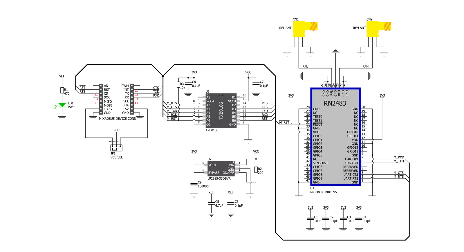
Click board™ Schematic
Step by step
Project assembly

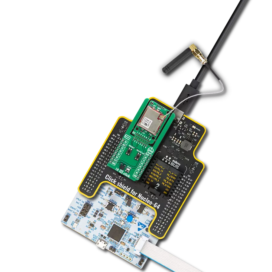
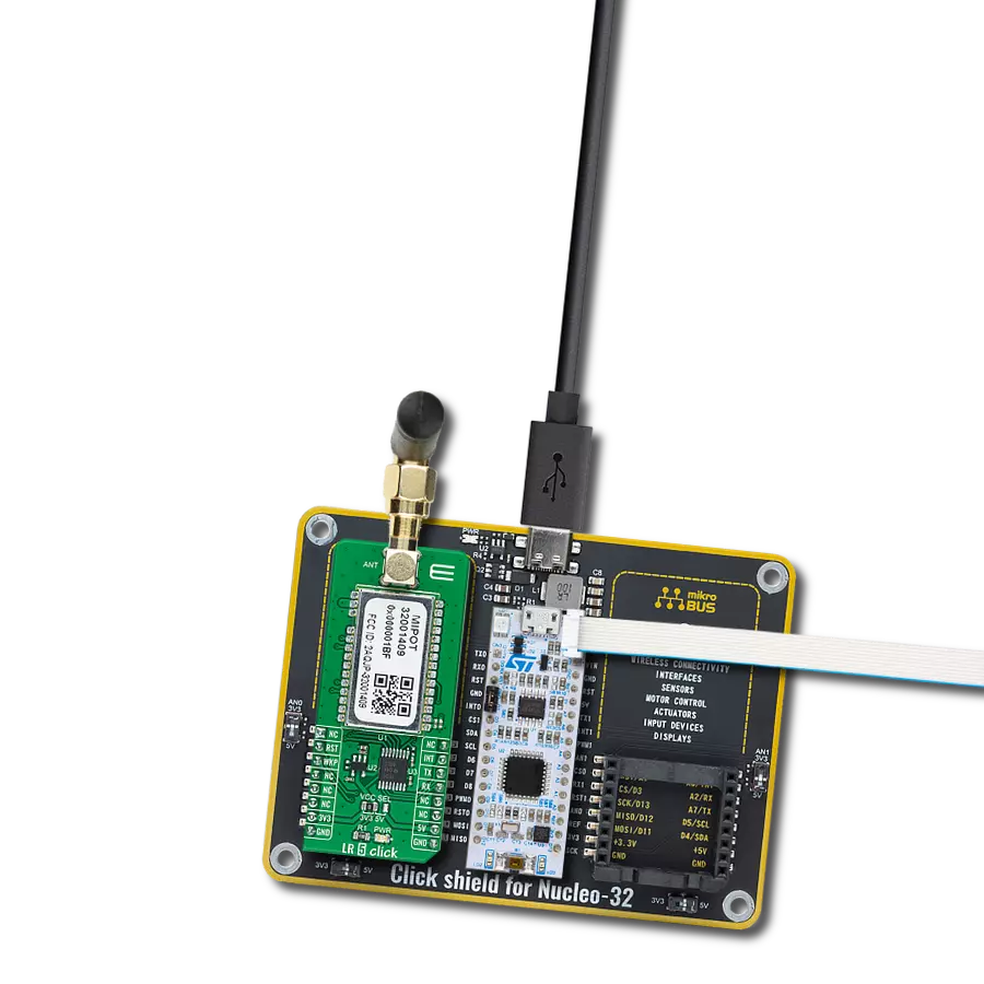
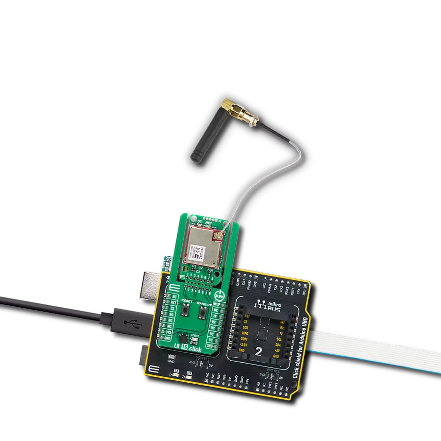
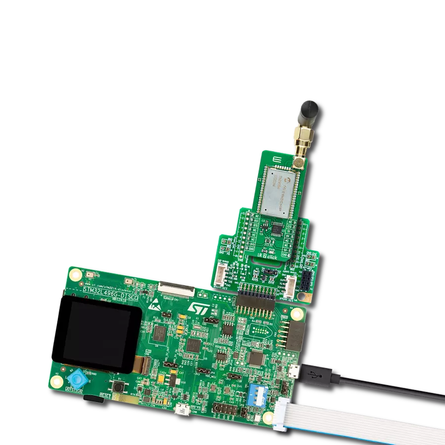
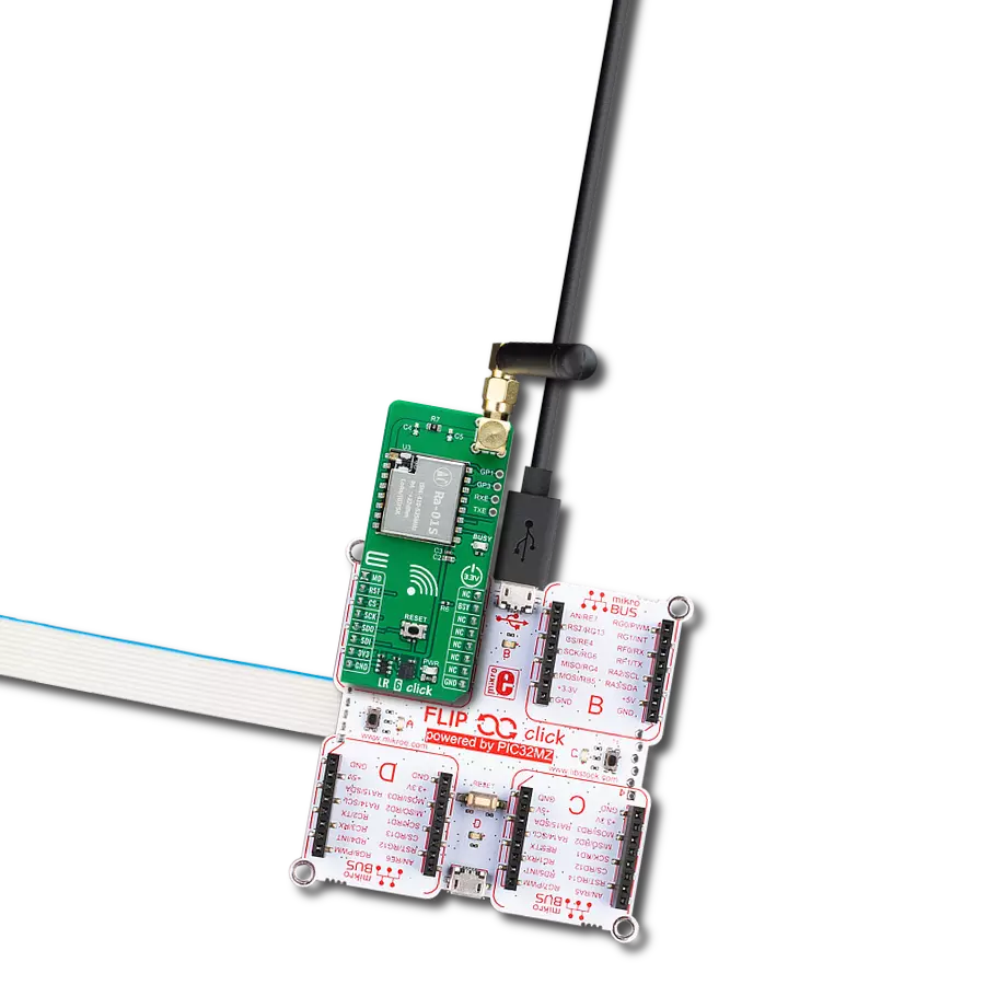
Start by selecting your development board and Click board™. Begin with the Flip&Click PIC32MZ as your development board.


Software Support
Library Description
This library contains API for LR Click driver.
Key functions:
lr_mac_tx- Function for writing mac parameterslr_join- Function for setting join modelr_tick_conf- Timer Configuration
Open Source
Code example
The complete application code and a ready-to-use project are available through the NECTO Studio Package Manager for direct installation in the NECTO Studio. The application code can also be found on the MIKROE GitHub account.
/*!
 * @file main.c
 * @brief LR Click Example.
 *
 * # Description
 * This example shows the usage of the LR Click board by transmitting and receiving data.
 *
 * The demo application is composed of two sections :
 *
 * ## Application Init
 * Initializes the driver and performs default configuration and reads System version.
 *
 * ## Application Task
 * Transmitter mode - sends one-by-one byte sequence of the desired message each second and
 * checks if it is sent successfully
 * Receiver mode - displays all the received characters on USB UART.
 *
 * @author Stefan Ilic
 *
 */

#include "board.h"
#include "log.h"
#include "lr.h"
#include "conversions.h"

#define PROCESS_COUNTER 5
#define PROCESS_RX_BUFFER_SIZE 300

// ------------------------------------------------------------------ VARIABLES

// #define DEMO_APP_RECEIVER
#define DEMO_APP_TRANSMITTER

static lr_t lr;
static log_t logger;

char send_hex[ 50 ];
char resp_buf[ 50 ];
uint8_t send_message[ 9 ] = { 'M', 'i', 'k', 'r', 'o', 'E', 13, 10, 0 };

/**
 * @brief LR data reading function.
 * @details This function reads data from device and concatenates data to application buffer.
 * @return Nothing.
 * @note None.
 */
static void lr_process ( void );

/**
 * @brief LR data is digit check function.
 * @details This function checks if data is a digit.
 * @param[in] c : Data to be checked.
 * @return @li @c 0 - Data isn't digit,
 *         @li @c 1 - Data is digit.
 * @note None.
 */
static bool is_digit ( char c );

/**
 * @brief LR hex data to int function.
 * @details This function is used to convert hex data into an int.
 * @param[in] origin : Hex data.
 * @param[out] result : Int data.
 * @return Nothing.
 * @note None.
 */
static void hex_to_int ( char *origin, uint8_t *result );

void application_init ( void )
{
    log_cfg_t log_cfg;  /**< Logger config object. */
    lr_cfg_t lr_cfg;  /**< Click config object. */

    /**
     * Logger initialization.
     * Default baud rate: 115200
     * Default log level: LOG_LEVEL_DEBUG
     * @note If USB_UART_RX and USB_UART_TX
     * are defined as HAL_PIN_NC, you will
     * need to define them manually for log to work.
     * See @b LOG_MAP_USB_UART macro definition for detailed explanation.
     */

    LOG_MAP_USB_UART( log_cfg );
    log_init( &logger, &log_cfg );
    log_info( &logger, " Application Init " );

    // Click initialization.
    lr_cfg_setup( &lr_cfg );
    LR_MAP_MIKROBUS( lr_cfg, MIKROBUS_1 );
    if ( UART_ERROR == lr_init( &lr, &lr_cfg ) )
    {
        log_error( &logger, " Communication init." );
        for ( ; ; );
    }

    lr_default_cfg( &lr, 0, 0 );

    lr_cmd( &lr, LR_CMD_SYS_GET_VER, resp_buf );
    log_printf( &logger, "System VER: %s \r\n", resp_buf );

    lr_cmd( &lr, LR_CMD_MAC_PAUSE, resp_buf );
    log_printf( &logger, "MAC PAUSE: %s \r\n", resp_buf );

    lr_cmd( &lr, LR_CMD_RADIO_SET_WDT, resp_buf );
    log_printf( &logger, "RADIO SET WDT 0: %s \r\n", resp_buf );

    log_info( &logger, " Application Task " );
}

void application_task ( void )
{
    lr_process( );

#ifdef DEMO_APP_RECEIVER
    char *ptr;
    uint8_t int_data;
    if ( LR_OK == lr_rx( &lr, LR_ARG_0, resp_buf ) )
    {
        resp_buf[ 12 ] = 0;
        ptr = ( char* ) &int_data;
        hex_to_int( &resp_buf[ 10 ], ptr );
        log_printf( &logger, "%c", int_data  );
    }
#endif
#ifdef DEMO_APP_TRANSMITTER
    for ( uint8_t cnt = 0; cnt < 9; cnt++ )
    {
        int8_to_hex( send_message[ cnt ], send_hex );
        if ( LR_OK == lr_tx( &lr, &send_hex[ 0 ] ) )
        {
            log_printf( &logger, " Response : %s \r\n", resp_buf );
        }
        Delay_ms ( 1000 );
    }
#endif
}

int main ( void )
{
    /* Do not remove this line or clock might not be set correctly. */
    #ifdef PREINIT_SUPPORTED
    preinit();
    #endif

    application_init( );

    for ( ; ; )
    {
        application_task( );
    }

    return 0;
}

static void lr_process ( void )
{
    int32_t rsp_size;

    char uart_rx_buffer[ PROCESS_RX_BUFFER_SIZE ] = { 0 };
    uint8_t check_buf_cnt;
    uint8_t process_cnt = PROCESS_COUNTER;

    while ( process_cnt != 0 )
    {
        rsp_size = lr_generic_read( &lr, &uart_rx_buffer, PROCESS_RX_BUFFER_SIZE );

        if ( rsp_size > 0 )
        {
            // Validation of the received data
            for ( check_buf_cnt = 0; check_buf_cnt < rsp_size; check_buf_cnt++ )
            {
                lr_put_char( &lr, uart_rx_buffer[ check_buf_cnt ] );
                lr_isr_process( &lr );
            }

            // Clear RX buffer
            memset( uart_rx_buffer, 0, PROCESS_RX_BUFFER_SIZE );
        }
        else
        {
            process_cnt--;

            // Process delay
            Delay_ms ( 100 );
        }
    }
}

static bool is_digit ( char c )
{
    if ( c >= '0' && c <= '9' )
    {
        return true;
    }

    return false;
}

static void hex_to_int ( char* origin, uint8_t* result )
{
    uint8_t len = strlen( origin );
    uint8_t idx, ptr, factor;

    if ( len > 0 )
    {
        *result = 0;
        factor = 1;

        for ( idx = len - 1; idx >= 0; idx-- )
        {
            if ( is_digit( *( origin + idx ) ) )
            {
                *result += ( *( origin + idx ) - '0' ) * factor;
               } else {
                    if ( *( origin + idx ) >= 'A' && *( origin + idx ) <= 'Z' )
                    {

                        ptr = ( *( origin + idx ) - 'A' ) + 10;

                    }
                    else
                    {
                        return;
                    }
                    *result += ( ptr * factor );
                }
                factor *= 16;
        }
    }
}

// ------------------------------------------------------------------------ END
Additional Support
Resources
Category:LoRa