Upgrade your audio game with SPQ0410HR5H-B and PIC32MZ2048EFH100
Hear the difference. Be heard!

Published Oct 02, 2023
Click board™
Mic Click
Dev. board
Flip&Click PIC32MZ
Compiler
NECTO Studio
MCU
PIC32MZ2048EFH100
Create crystal-clear audio recordings with your own custom-built microphone system
A
A
Hardware Overview
How does it work?
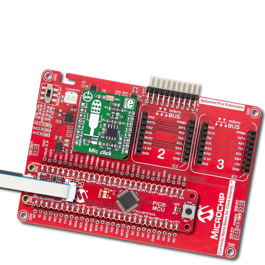
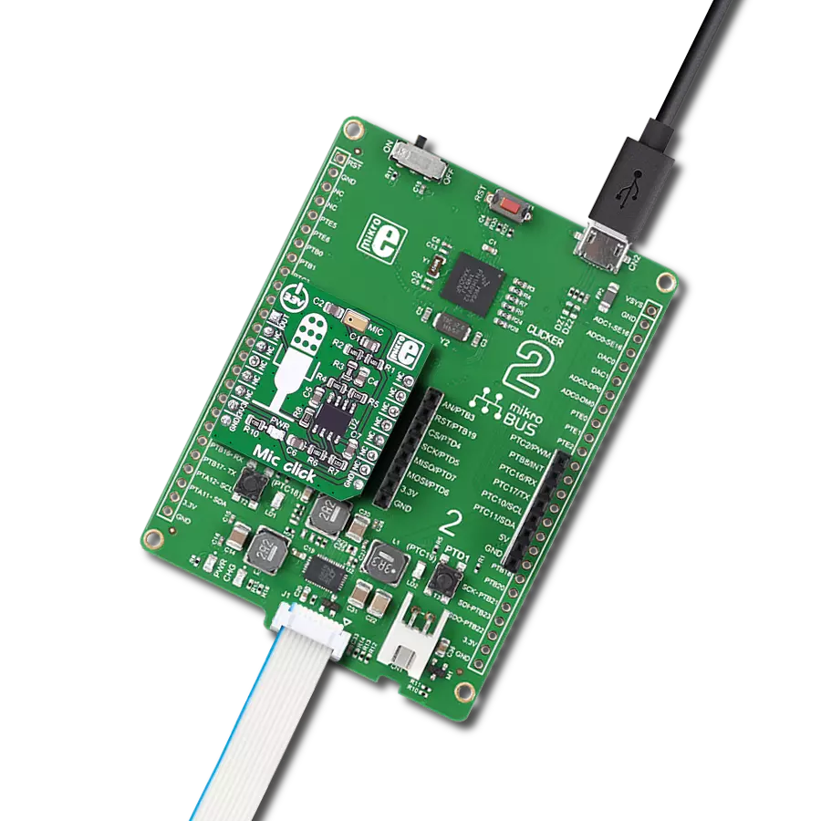
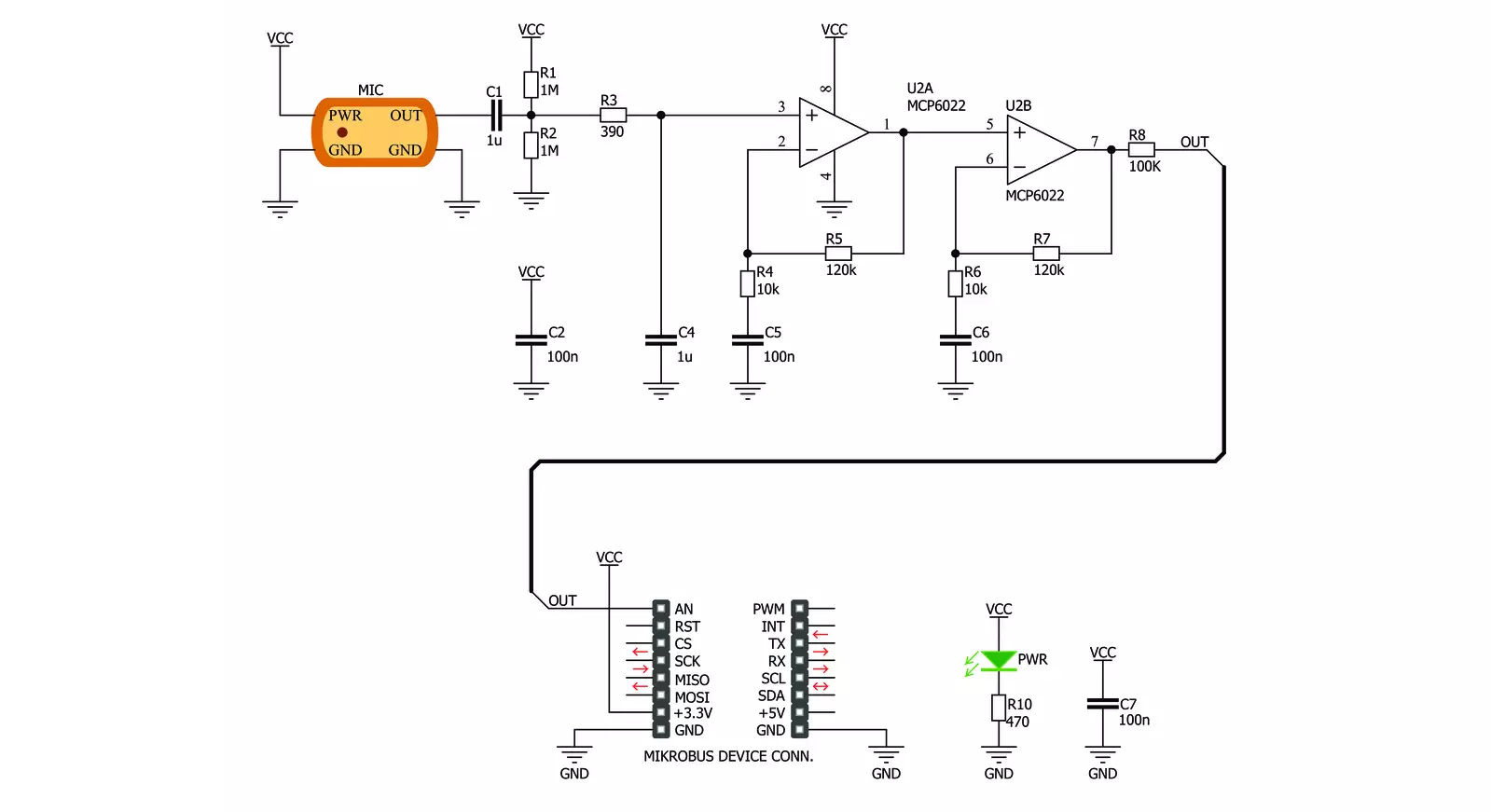
Mic Click is based on the SPQ0410HRSH-B, a slim ultra-mini SiSonic™ microphone specification with maximum RF protection and ultra-narrow design from Knowles. It is a MEMS microphone and consists of an acoustic sensor, a low noise input buffer, and an output amplifier. It is a very reliable microphone, resistant to mechanical shocks, vibrations, thermal shocks, low and high temperatures, ESD-HBM, and more. It is not resistant to high pressure and vacuum. The
microphone is top-port oriented and has a typical sensitivity of -42dB at 94dB SPL, with a 59dB signal-to-noise ratio. Mic Click uses an analog OUT pin of the mikroBUS™ socket to communicate with the host MCU. The analog output from the microphone to the OUT pin goes through the MCP6022, a rail-to-rail input/output 10MHz Op Amp from Microchip. This operational amplifier has a wide bandwidth, low noise, low input offset voltage, and low distortion and amplifies the
microphone's output with high performance. This Click board™ can be operated only with a 3.3V logic voltage level. The board must perform appropriate logic voltage level conversion before using MCUs with different logic levels. Also, it comes equipped with a library containing functions and an example code that can be used as a reference for further development.


Features overview
Development board
Flip&Click PIC32MZ is a compact development board designed as a complete solution that brings the flexibility of add-on Click boards™ to your favorite microcontroller, making it a perfect starter kit for implementing your ideas. It comes with an onboard 32-bit PIC32MZ microcontroller, the PIC32MZ2048EFH100 from Microchip, four mikroBUS™ sockets for Click board™ connectivity, two USB connectors, LED indicators, buttons, debugger/programmer connectors, and two headers compatible with Arduino-UNO pinout. Thanks to innovative manufacturing technology,
it allows you to build gadgets with unique functionalities and features quickly. Each part of the Flip&Click PIC32MZ development kit contains the components necessary for the most efficient operation of the same board. In addition, there is the possibility of choosing the Flip&Click PIC32MZ programming method, using the chipKIT bootloader (Arduino-style development environment) or our USB HID bootloader using mikroC, mikroBasic, and mikroPascal for PIC32. This kit includes a clean and regulated power supply block through the USB Type-C (USB-C) connector. All communication
methods that mikroBUS™ itself supports are on this board, including the well-established mikroBUS™ socket, user-configurable buttons, and LED indicators. Flip&Click PIC32MZ development kit allows you to create a new application in minutes. Natively supported by Mikroe software tools, it covers many aspects of prototyping thanks to a considerable number of different Click boards™ (over a thousand boards), the number of which is growing every day.

Microcontroller Overview
MCU Card / MCU

Architecture
PIC32
MCU Memory (KB)
2048
Silicon Vendor
Microchip
Pin count
100
RAM (Bytes)
524288
Used MCU Pins
mikroBUS™ mapper
Take a closer look
Click board™ Schematic
Step by step
Project assembly

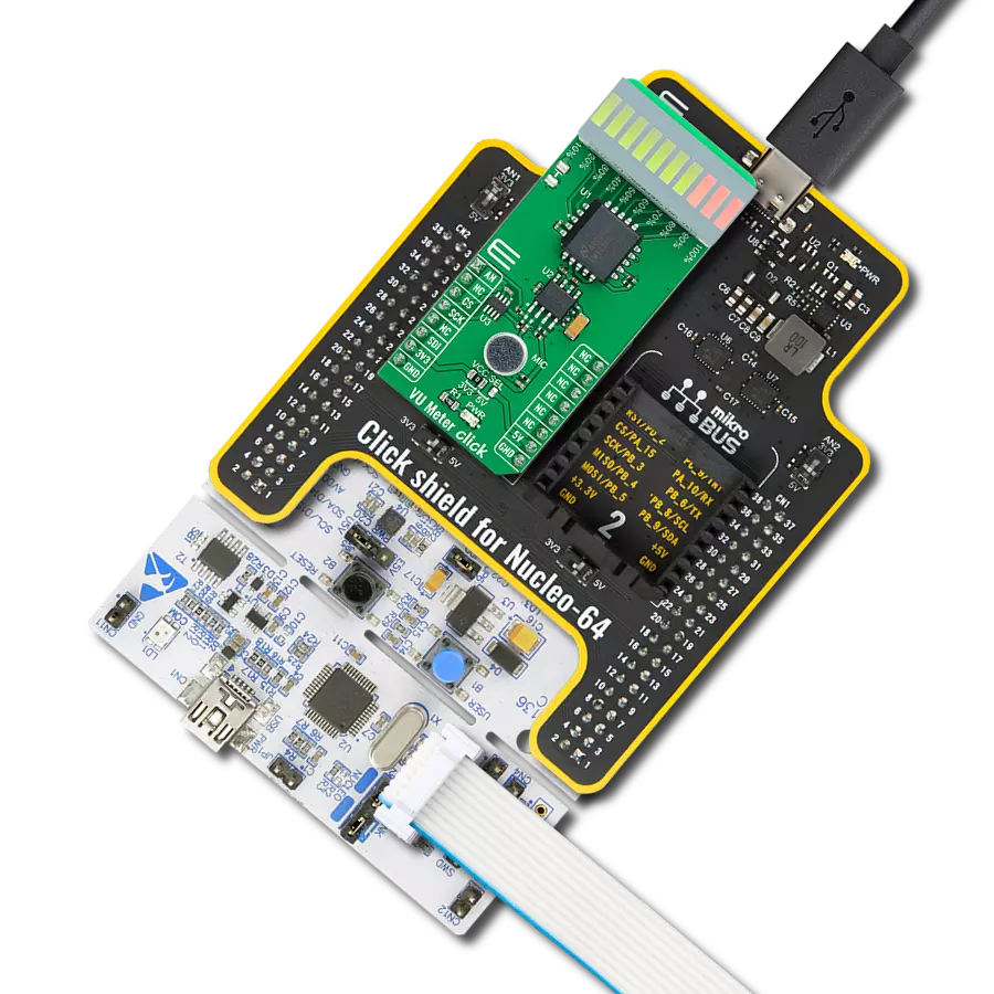
Start by selecting your development board and Click board™. Begin with the Flip&Click PIC32MZ as your development board.


Software Support
Library Description
This library contains API for MIC Click driver.
Key functions:
mic_generic_read- This function read ADC data
Open Source
Code example
The complete application code and a ready-to-use project are available through the NECTO Studio Package Manager for direct installation in the NECTO Studio. The application code can also be found on the MIKROE GitHub account.
/*!
 * \file
 * \brief Mic Click example
 *
 * # Description
 * This example showcases the initialization and configuration of the Click and logger
 * modules and later on reads and displays data recorded by the mic.
 *
 * The demo application is composed of two sections :
 *
 * ## Application Init
 * Initializes LOG communication, ADC and configures AN pin as input on MIKROBUS1.
 *
 * ## Application Task
 * Reads 12 bit ADC data from AN pin and displays it using the logger module.
 *
 * \author MikroE Team
 *
 */
// ------------------------------------------------------------------- INCLUDES

#include "board.h"
#include "log.h"
#include "mic.h"

// ------------------------------------------------------------------ VARIABLES

static mic_t mic;
static log_t logger;

// ------------------------------------------------------ APPLICATION FUNCTIONS

void application_init ( void )
{
    log_cfg_t log_cfg;
    mic_cfg_t cfg;

    /**
     * Logger initialization.
     * Default baud rate: 115200
     * Default log level: LOG_LEVEL_DEBUG
     * @note If USB_UART_RX and USB_UART_TX
     * are defined as HAL_PIN_NC, you will
     * need to define them manually for log to work.
     * See @b LOG_MAP_USB_UART macro definition for detailed explanation.
     */
    LOG_MAP_USB_UART( log_cfg );
    log_init( &logger, &log_cfg );
    log_info( &logger, "---- Application Init ----" );

    //  Click initialization.

    mic_cfg_setup( &cfg );
    MIC_MAP_MIKROBUS( cfg, MIKROBUS_1 );
    mic_init( &mic, &cfg );
}

void application_task ( void )
{
    mic_data_t tmp;

    //  Task implementation.

    tmp = mic_generic_read ( &mic );

    log_printf( &logger, "** ADC value : [DEC]- %d, [HEX]- 0x%x \r\n", tmp, tmp );

    Delay_ms ( 1000 );
}

int main ( void )
{
    /* Do not remove this line or clock might not be set correctly. */
    #ifdef PREINIT_SUPPORTED
    preinit();
    #endif

    application_init( );

    for ( ; ; )
    {
        application_task( );
    }

    return 0;
}

// ------------------------------------------------------------------------ END
Additional Support
Resources
Category:Microphone