Experience synchronized lighting effects with ALI782 and PIC32MZ2048EFM100
Smart lighting evolution starts here
Published Sep 05, 2023
Click board™
Light Temp Click
Dev. board
Curiosity PIC32 MZ EF
Compiler
NECTO Studio
MCU
PIC32MZ2048EFM100
Our dual-channel LED driver empowers SCL applications with independent control over two lighting channels, enabling dynamic color tuning and personalized lighting experiences
A
A
Hardware Overview
How does it work?
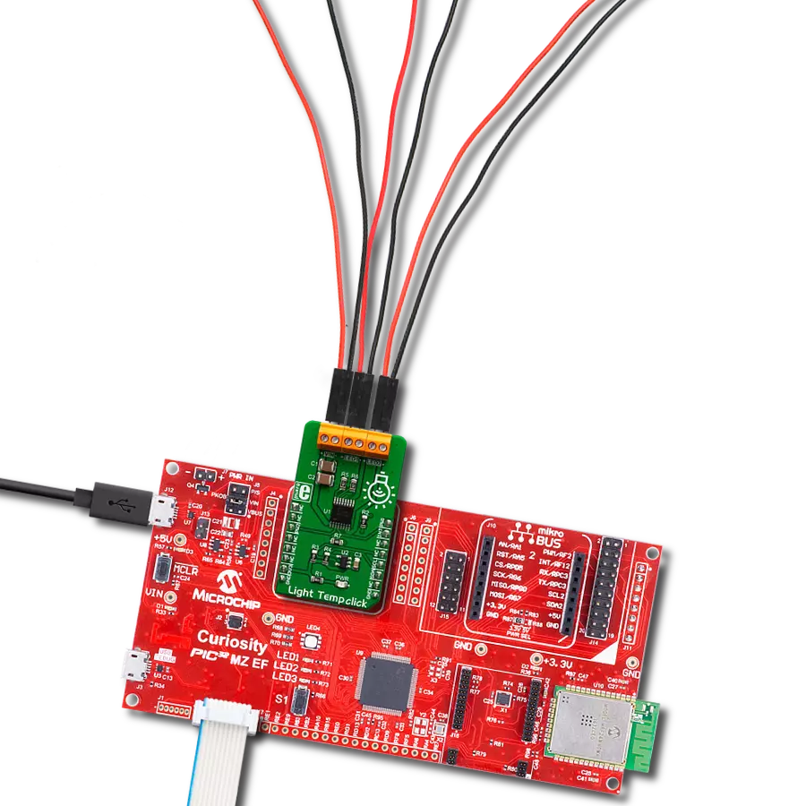
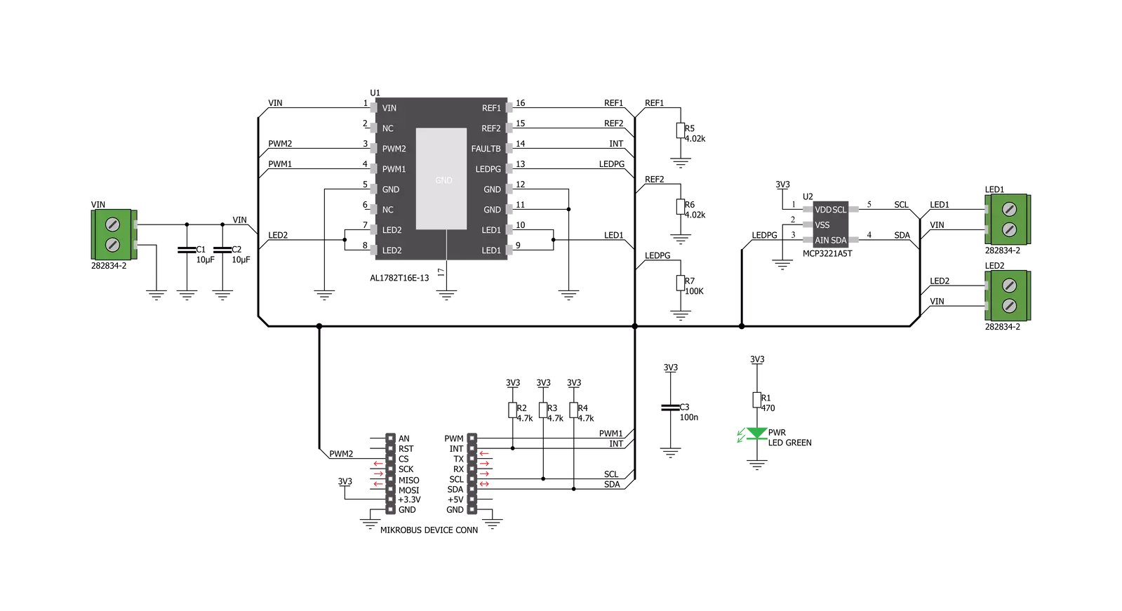
Light Temp Click is based on the AL1782, a dual-channel PWM dimmable linear LED driver by Diodes Incorporated. It is a constant-current driver, which can sink up to 1500mA combined or up to 750mA per channel. It has two low-side current sinks, which allow LED strips or LED bulbs to be connected in the common-anode topology for increased effectiveness and power optimization. Note that the constant current on this Click board™ is 750mA per channel. The AL1782 IC can be operated with a PWM signal in the frequency range from 1kHz to 40kHz. Applying the PWM signal with a duty cycle of less than 4ms makes it possible to tune the light intensity of the connected LED light element. A LOW pulse width of more than 4ms will set the device into the low-power mode (suspend). The lowest light intensity that can be reached by applying the PWM frequency of 1kHz is 0.1%, while 40kHz allows the lowest brightness level of 4% of the full light intensity. A High PWM frequency allows for less visible flickering but simultaneously limits the lowest light intensity level. PWM1 and PWM2 pins of the AL1782 are routed to the mikroBUS™ PWM and CS pins and are labeled as PW1 and PW2. Adaptive Thermal Management (ATM) scheme is one of the key features of the AL1782. It can be used to optimize the power consumption by
adjusting the voltage of the external power supply unit (PSU): the excessive voltage applied to the connected LED will be dissipated as heat within the AL1782. Therefore, the voltage level of the external PSU should be kept above the forward voltage of the connected LED plus minimum voltage headroom (VF + VLED_REG). The ATM injects current through the LEDPG pin of the AL1782. This current is converted to a voltage level, and it is sampled by the MCP3221, a low-power 12-bit A/D converter with an I2C interface, by Microchip. It has its I2C pins routed to the respective mikroBUS™ I2C pins, allowing the host MCU to read the LEDPG voltage and adjust the PSU voltage. Please note that if an external PSU with no external regulation is used, its voltage should stay within the mentioned range (VF of the connected LED element + VLEDx_REG as per AL1782 datasheet). However, the voltage should always stay below 30V. The AL1782 IC also integrates many protection features for increased reliability: undervoltage, open or short circuit at the output, and thermal protection. If any of these protections become activated, a fault event will be reported on a dedicated pin labeled FAULTB. This pin is routed to the mikroBUS™ INT pin and is asserted to a LOW logic level when a fault event occurs. Deep Dimming Capability helps with
power efficiency. Subjective perception of the light intensity differs from the measured light. For example, the light intensity of 10% (with respect to the applied duty cycle) is perceived as 32% of the full light intensity. Deep Dimming Capability helps with energy saving, providing an optimal light output. Deep Dimming down to 0.1% is possible with the AL1782 IC since it can be operated with a pulse width as low as one µS while still providing good linearity. Light Temp click is designed to use an external PSU and an MCU. The full potential of the Light Temp click is achieved when combined with a dedicated light temperature and color sensing Click board™ such as Spectral click. By receiving information about the ambient light color temperature and white balance from the Spectral click, the MCU can generate a PWM signal concerning the required CCT tuning and send it to the Light Temp click to regulate the ambient lighting color. This Click board™ can be operated only with a 3.3V logic voltage level. The board must perform appropriate logic voltage level conversion before using MCUs with different logic levels. Also, it comes equipped with a library containing functions and an example code that can be used as a reference for further development.

Features overview
Development board
Curiosity PIC32 MZ EF development board is a fully integrated 32-bit development platform featuring the high-performance PIC32MZ EF Series (PIC32MZ2048EFM) that has a 2MB Flash, 512KB RAM, integrated FPU, Crypto accelerator, and excellent connectivity options. It includes an integrated programmer and debugger, requiring no additional hardware. Users can expand
functionality through MIKROE mikroBUS™ Click™ adapter boards, add Ethernet connectivity with the Microchip PHY daughter board, add WiFi connectivity capability using the Microchip expansions boards, and add audio input and output capability with Microchip audio daughter boards. These boards are fully integrated into PIC32’s powerful software framework, MPLAB Harmony,
which provides a flexible and modular interface to application development a rich set of inter-operable software stacks (TCP-IP, USB), and easy-to-use features. The Curiosity PIC32 MZ EF development board offers expansion capabilities making it an excellent choice for a rapid prototyping board in Connectivity, IOT, and general-purpose applications.

Microcontroller Overview
MCU Card / MCU

Architecture
PIC32
MCU Memory (KB)
2048
Silicon Vendor
Microchip
Pin count
100
RAM (Bytes)
524288
Used MCU Pins
mikroBUS™ mapper
Take a closer look
Click board™ Schematic
Step by step
Project assembly

Start by selecting your development board and Click board™. Begin with the Curiosity PIC32 MZ EF as your development board.


Software Support
Library Description
This library contains API for Light Temp Click driver.
Key functions:
lighttemp_get_interrupt_state- Get INT pin statelighttemp_get_pg_voltage- Get voltagelighttemp_cs_set_state- Start PW2 module.
Open Source
Code example
The complete application code and a ready-to-use project are available through the NECTO Studio Package Manager for direct installation in the NECTO Studio. The application code can also be found on the MIKROE GitHub account.
/*!
 * @file
 * @brief LightTemp Click example
 *
 * # Description
 * This application controls light intensity of LEDs.
 *
 * The demo application is composed of two sections :
 *
 * ## Application Init
 * Initialization driver init and pwm init for all LED's
 *
 * ## Application Task
 * This is an example that demonstrates the use of the Light Temp Click board.
 * This example shows the automatic control of the LED light intensity,
 * the first intensity of light is rising and then the intensity of light is falling.
 * Results are being sent to the Usart Terminal where you can track their changes.
 *
 * ## NOTE
 * In order to control LED2 via PWM, the PWM module should be available at CS pin.
 *
 * @author Nikola Peric
 *
 */
// ------------------------------------------------------------------- INCLUDES

#include "board.h"
#include "log.h"
#include "lighttemp.h"

// ------------------------------------------------------------------ VARIABLES

static lighttemp_t lighttemp;
static log_t logger;

// ------------------------------------------------------ APPLICATION FUNCTIONS

void application_init ( void )
{
    log_cfg_t log_cfg;
    lighttemp_cfg_t cfg;

    /**
     * Logger initialization.
     * Default baud rate: 115200
     * Default log level: LOG_LEVEL_DEBUG
     * @note If USB_UART_RX and USB_UART_TX
     * are defined as HAL_PIN_NC, you will
     * need to define them manually for log to work.
     * See @b LOG_MAP_USB_UART macro definition for detailed explanation.
     */
    LOG_MAP_USB_UART( log_cfg );
    log_init( &logger, &log_cfg );
    log_info( &logger, "---- Application Init ----" );
    Delay_ms ( 100 );

    //  Click initialization.

    lighttemp_cfg_setup( &cfg );
    LIGHTTEMP_MAP_MIKROBUS( cfg, MIKROBUS_1 );
    lighttemp_init( &lighttemp, &cfg );

    lighttemp_led1_set_duty_cycle ( &lighttemp, 0.0 );
    lighttemp_led2_set_duty_cycle ( &lighttemp, 0.0 );

    log_info( &logger, "---- Application Task ----" );

    Delay_ms ( 500 );
}

void application_task ( void )
{
    static int8_t duty_cnt = 1;
    static int8_t duty_inc = 1;
    float duty = duty_cnt / 10.0;

    lighttemp_led1_set_duty_cycle ( &lighttemp, duty );
    lighttemp_led2_set_duty_cycle ( &lighttemp, duty );

    lighttemp_led1_pwm_start( &lighttemp );
    lighttemp_led2_pwm_start( &lighttemp );

    log_printf( &logger, "Duty: %d%%\r\n", ( uint16_t )( duty_cnt * 10 ) );
    Delay_ms ( 500 );

    if ( 10 == duty_cnt )
    {
        duty_inc = -1;
    }
    else if ( 0 == duty_cnt )
    {
        duty_inc = 1;
    }
    duty_cnt += duty_inc;
}

int main ( void )
{
    /* Do not remove this line or clock might not be set correctly. */
    #ifdef PREINIT_SUPPORTED
    preinit();
    #endif

    application_init( );

    for ( ; ; )
    {
        application_task( );
    }

    return 0;
}

// ------------------------------------------------------------------------ END
Additional Support
Resources
Category:LED Drivers


