Achieve reliable RF communication for diverse applications with cc2500 and PIC32MZ2048EFM100
2.4GHz transceiver capable of various modulation schemes like OOK, 2-FSK, GFSK, and MSK

Published Jan 31, 2024
Click board™
ccRF Click
Dev. board
Curiosity PIC32 MZ EF
Compiler
NECTO Studio
MCU
PIC32MZ2048EFM100
Develop a tiny radio station for things like remote control, home appliances, or other gadgets that need to send or receive information wirelessly
A
A
Hardware Overview
How does it work?
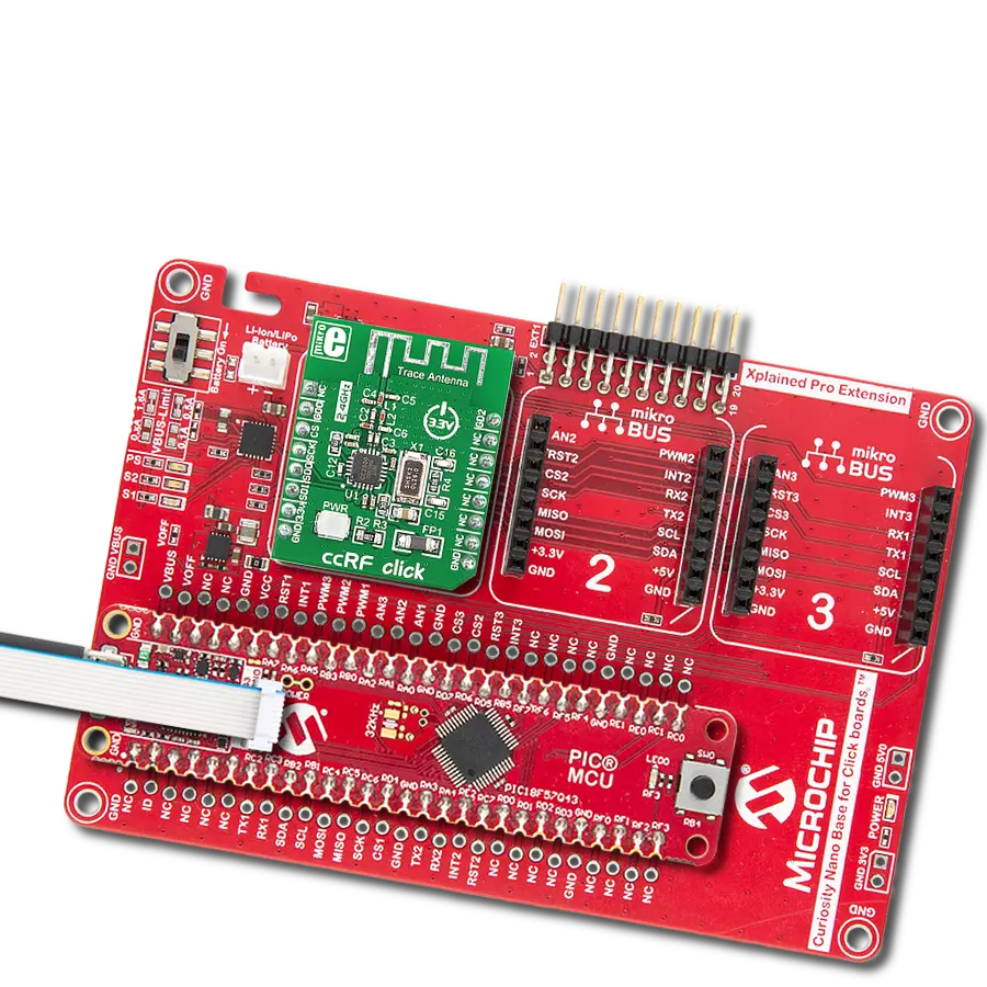
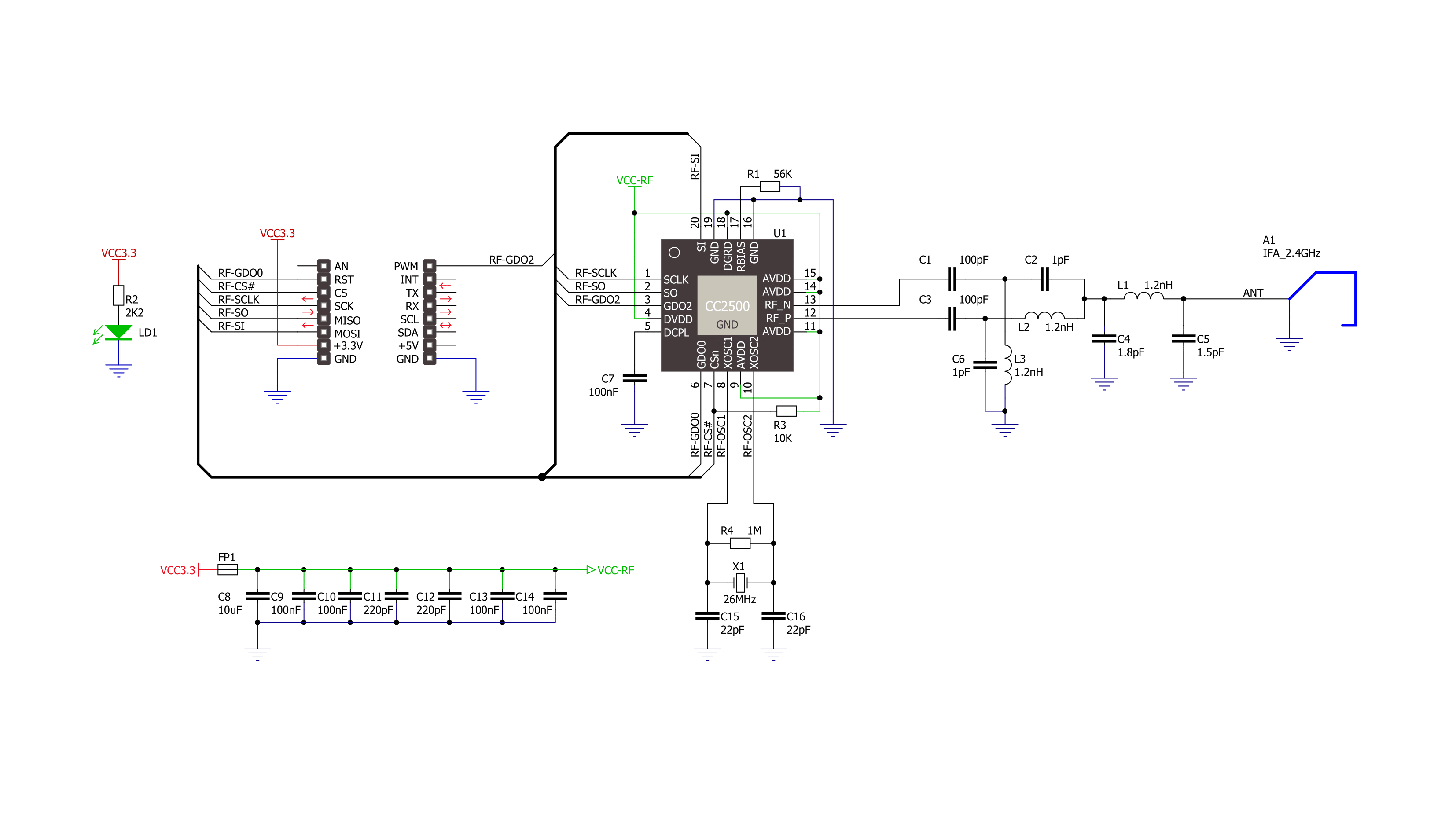
ccRF Click is based on the CC2500, a low-power, high-performance 2.4GHz transceiver from Texas Instruments, operating in the worldwide ISM frequency band from 2400MHz to 2483.5. The CC2500 has excellent receiver selectivity and blocking performance with an embedded packet handler engine suitable for packet-oriented systems. It also has a highly configurable baseband modem that supports various modulation formats (OOK, 2-FSK, GFSK, and MSK) and user-configurable parameters like frequency channel, output power, and air data rate. The transceiver has a programmable data rate from 1.2 to 500kBaud depending on frequency range over a PCB trace 2.4GHz antenna, making the ccRF Click
suitable for ultra-low power designs. The CC2500 has a built-in state machine that switches between different operation states (modes) to achieve optimum performance for many applications. Change of the states is performed using command strobes or internal events such as TX FIFO underflow. These states take care of Sleep, Idle, Active, Receive or Transmit modes, Wake-on-Radio (WOR), and more. In addition, the CC2500 comes with on-chip support for synchronization word detection, address check, flexible packet length, and automatic CRC handling. The ccRF Click uses an SPI serial interface to communicate with the host MCU. There are two pins in addition, the GD0 and GD2, routed where the RST and PWM pins of
the mikroBUS™ socket stand by default. With the GD2 as a digital output pin, the user can get test signals, FIFO status, clear channel indicator, serial output RX data, and more. The GD0 as a digital output pin can be used to get the same data as the GD2, plus it can provide serial input TX data. This Click board™ can only be operated with a 3.3V logic voltage level. The board must perform appropriate logic voltage level conversion before using MCUs with different logic levels. However, the Click board™ comes equipped with a library containing functions and an example code that can be used as a reference for further development.

Features overview
Development board
Curiosity PIC32 MZ EF development board is a fully integrated 32-bit development platform featuring the high-performance PIC32MZ EF Series (PIC32MZ2048EFM) that has a 2MB Flash, 512KB RAM, integrated FPU, Crypto accelerator, and excellent connectivity options. It includes an integrated programmer and debugger, requiring no additional hardware. Users can expand
functionality through MIKROE mikroBUS™ Click™ adapter boards, add Ethernet connectivity with the Microchip PHY daughter board, add WiFi connectivity capability using the Microchip expansions boards, and add audio input and output capability with Microchip audio daughter boards. These boards are fully integrated into PIC32’s powerful software framework, MPLAB Harmony,
which provides a flexible and modular interface to application development a rich set of inter-operable software stacks (TCP-IP, USB), and easy-to-use features. The Curiosity PIC32 MZ EF development board offers expansion capabilities making it an excellent choice for a rapid prototyping board in Connectivity, IOT, and general-purpose applications.

Microcontroller Overview
MCU Card / MCU

Architecture
PIC32
MCU Memory (KB)
2048
Silicon Vendor
Microchip
Pin count
100
RAM (Bytes)
524288
Used MCU Pins
mikroBUS™ mapper
Take a closer look
Click board™ Schematic
Step by step
Project assembly

Start by selecting your development board and Click board™. Begin with the Curiosity PIC32 MZ EF as your development board.


Software Support
Library Description
This library contains API for ccRF Click driver.
Key functions:
ccrf_writeBytes- Sequential ( burst ) write function.ccrf_readBytes- Sequential ( burst ) read function.ccrf_defaultConfiguration- Default configuration function.
Open Source
Code example
The complete application code and a ready-to-use project are available through the NECTO Studio Package Manager for direct installation in the NECTO Studio. The application code can also be found on the MIKROE GitHub account.
/*!
 * \file
 * \brief ccRF Click example
 *
 * # Description
 * This example demonstrates the use of an ccRF Click board by showing
 * the communication between the two Click boards configured as a receiver and transmitter.
 *
 * The demo application is composed of two sections :
 *
 * ## Application Init
 * Initializes the driver and logger, performs the Click default configuration and
 * displays the selected application mode.
 *
 * ## Application Task
 * Depending on the selected mode, it reads all the received data or sends the desired message
 * every 2 seconds.
 *
 * \author MikroE Team
 *
 */

#include "board.h"
#include "log.h"
#include "ccrf.h"

// Comment out the line below in order to switch the application mode to receiver
#define DEMO_APP_TRANSMITTER

// Text message to send in the transmitter application mode
#define DEMO_TEXT_MESSAGE           "MIKROE - ccRF Click board\0"

static ccrf_t ccrf;
static log_t logger;

void application_init ( void )
{
    log_cfg_t log_cfg;
    ccrf_cfg_t cfg;

    /**
     * Logger initialization.
     * Default baud rate: 115200
     * Default log level: LOG_LEVEL_DEBUG
     * @note If USB_UART_RX and USB_UART_TX
     * are defined as HAL_PIN_NC, you will
     * need to define them manually for log to work.
     * See @b LOG_MAP_USB_UART macro definition for detailed explanation.
     */
    LOG_MAP_USB_UART( log_cfg );
    log_init( &logger, &log_cfg );
    log_info( &logger, " Application Init " );

    // Click initialization.
    ccrf_cfg_setup( &cfg );
    CCRF_MAP_MIKROBUS( cfg, MIKROBUS_1 );
    ccrf_init( &ccrf, &cfg );

    ccrf_default_cfg( &ccrf );

#ifdef DEMO_APP_TRANSMITTER
    log_printf( &logger, " Application Mode: Transmitter\r\n" );
#else
    log_printf( &logger, " Application Mode: Receiver\r\n" );
#endif
    log_info( &logger, " Application Task " );
}

void application_task ( void )
{
#ifdef DEMO_APP_TRANSMITTER
    ccrf_transmit_packet( &ccrf, DEMO_TEXT_MESSAGE, strlen( DEMO_TEXT_MESSAGE ) );
    log_printf( &logger, " The message \"%s\" has been sent!\r\n", ( char * ) DEMO_TEXT_MESSAGE );
    Delay_ms ( 1000 );
    Delay_ms ( 1000 );
#else
    uint8_t data_buf[ 64 ] = { 0 };
    uint8_t data_len = sizeof( data_buf );
    if ( CCRF_CRC_OK == ccrf_receive_packet( &ccrf, data_buf, &data_len ) )
    {
        log_printf( &logger, " A new message has received: \"" );
        for ( uint16_t cnt = 0; cnt < data_len; cnt++ )
        {
            log_printf( &logger, "%c", data_buf[ cnt ] );
        }
        log_printf( &logger, "\"\r\n" );
    }
#endif
}

int main ( void )
{
    /* Do not remove this line or clock might not be set correctly. */
    #ifdef PREINIT_SUPPORTED
    preinit();
    #endif

    application_init( );

    for ( ; ; )
    {
        application_task( );
    }

    return 0;
}


// ------------------------------------------------------------------------ END
Additional Support
Resources
Category:2.4 GHz Transceivers