Create your own gateway to energy-efficient IoT networks with ETRX357 and PIC32MZ2048EFM100
Power your IoT dreams with ZigBee magic!

Published Nov 08, 2023
Click board™
ZigBee Click
Dev. board
Curiosity PIC32 MZ EF
Compiler
NECTO Studio
MCU
PIC32MZ2048EFM100
Discover the potential of our ZigBee Radio module, meticulously designed to conserve power while delivering robust wireless connectivity, ideal for IoT applications demanding efficiency and reliability.
A
A
Hardware Overview
How does it work?
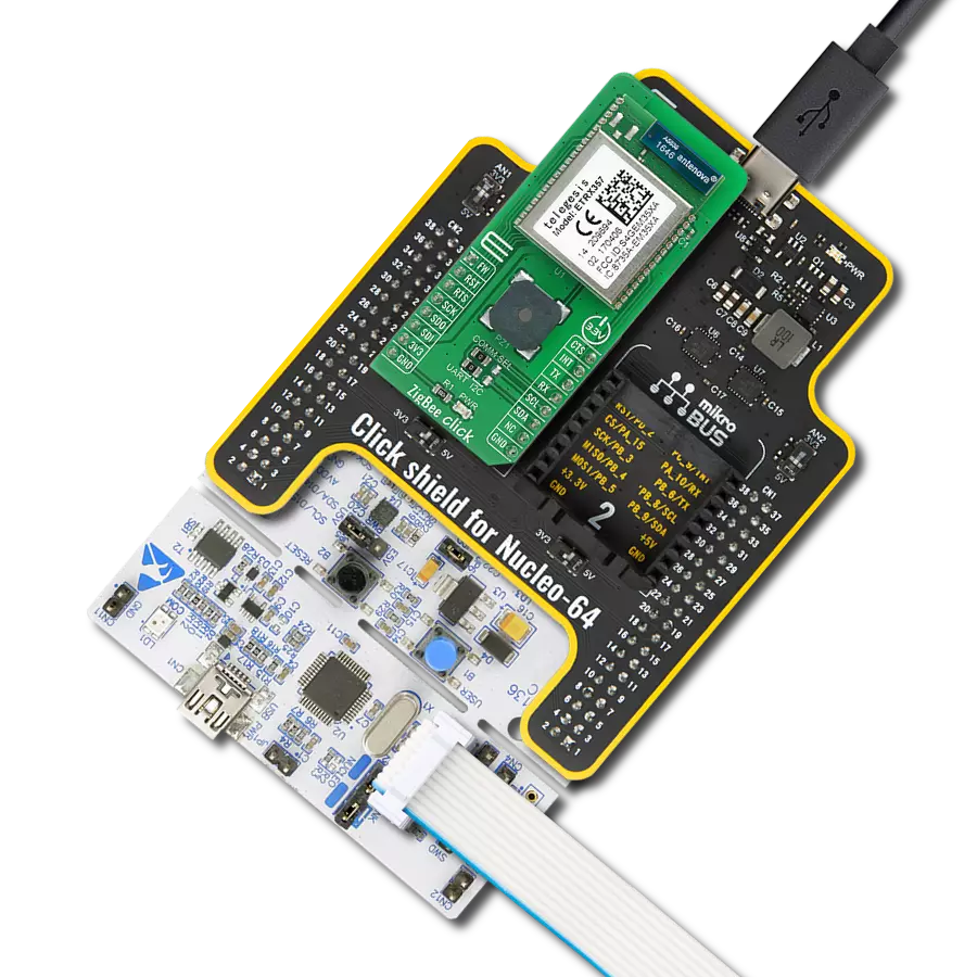
ZigBee Click is based on the ETRX357, a low power Zigbee Radio module integrating a 2.4 GHz compliant transceiver with many advanced peripherals from Silicon Labs. The ZigBee protocol is a set of standards for wireless connectivity for usage between any devices over short to medium distances. It uses the IEEE 802.15.4 radio specification running on the 2.4GHz band, plus three additional layers for networking, security, and applications. What makes this module unique is its use of a mesh network architecture which, in bucket chain style, passes data from one node to the next until it lands at its destination. The ETRX357 module is pre-loaded with a standalone bootloader that supports over-the-air bootloading as well as serial bootloading of the new firmware, using the FW pin on the ZigBee Click. The module is controlled using the default firmware consisting of simple AT commands. Parameters that define the functionality of the module and also allow standalone functionality are saved in non-volatile memory organized in so-called S-Registers.
The commands and responses pass through the serial port of the ETRX357 as ASCII text, so a simple terminal application will usually suffice. The industry-standard serial wire, JTAG programming, and debugging interfaces together with the standard ARM system debug components help to streamline any custom software development. In addition to this, several MAC functions are also implemented in hardware to help to maintain the strict timing requirements imposed by the ZigBee and IEEE802.15.4 standards. The module is also able to act as a coordinator and Trust Centre through external host control. The AT-style command line supplies all the tools required to set up and manage a Zigbee network by allowing easy access to the low-level functionality of the stack. ZigBee Click communicates with MCU using the UART interface as its default communication protocol, but it is also left the option for the user to use other interfaces such as SPI and I2C if he wants to configure the module and write the library by himself. The selection
between UART and I2C can be done by positioning SMD jumpers labeled as COMM SEL to an appropriate position. Note that all the jumpers must be placed to the same side, or else the Click board™ may become unresponsive. Additional functionality such as reset and interrupt are provided and routed at RST and INT pins of the mikroBUSTM, as well as serial UART connections CTS and RTS, routed on the CS and PWM mikroBUSTM pins. To simplify deployment, the Click boardTM features the CMT-8540S-SMT magnetic buzzer controlled by the ZigBee module used for audible signalization and notification. You can create different sound patterns using the Sound library supported in our compilers. Signal frequency determines the sound pitch, and the duty cycle determines the amplitude (sound volume). This Click board™ is designed to be operated only with a 3.3V logic level. A proper logic voltage level conversion should be performed before the Click board™ is used with MCUs with different logic levels.

Features overview
Development board
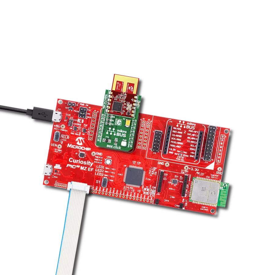
Curiosity PIC32 MZ EF development board is a fully integrated 32-bit development platform featuring the high-performance PIC32MZ EF Series (PIC32MZ2048EFM) that has a 2MB Flash, 512KB RAM, integrated FPU, Crypto accelerator, and excellent connectivity options. It includes an integrated programmer and debugger, requiring no additional hardware. Users can expand
functionality through MIKROE mikroBUS™ Click™ adapter boards, add Ethernet connectivity with the Microchip PHY daughter board, add WiFi connectivity capability using the Microchip expansions boards, and add audio input and output capability with Microchip audio daughter boards. These boards are fully integrated into PIC32’s powerful software framework, MPLAB Harmony,
which provides a flexible and modular interface to application development a rich set of inter-operable software stacks (TCP-IP, USB), and easy-to-use features. The Curiosity PIC32 MZ EF development board offers expansion capabilities making it an excellent choice for a rapid prototyping board in Connectivity, IOT, and general-purpose applications.

Microcontroller Overview
MCU Card / MCU

Architecture
PIC32
MCU Memory (KB)
2048
Silicon Vendor
Microchip
Pin count
100
RAM (Bytes)
524288
Used MCU Pins
mikroBUS™ mapper
Take a closer look
Click board™ Schematic

Step by step
Project assembly

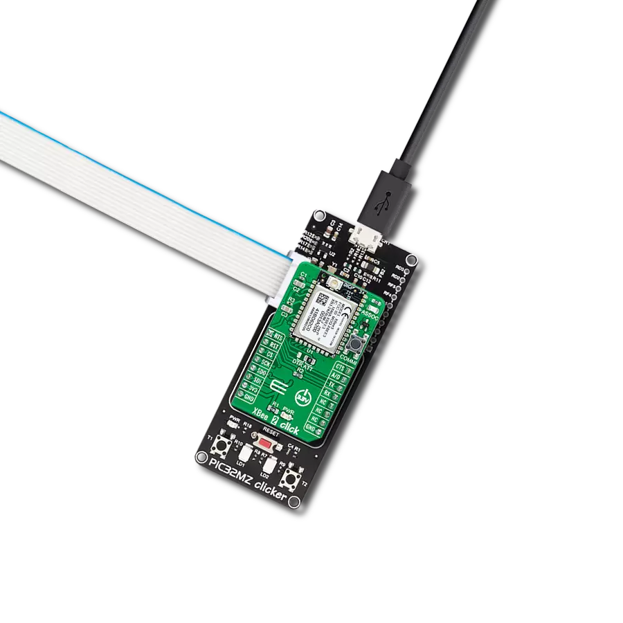
Start by selecting your development board and Click board™. Begin with the Curiosity PIC32 MZ EF as your development board.


Software Support
Library Description
This library contains API for ZigBee Click driver.
Key functions:
zigbee_send_at- Function merges two string and sends it to device.zigbee_resp- Function checking driver buffer string.zigbee_set_pin_rst- Function setting RST pin status.
Open Source
Code example
The complete application code and a ready-to-use project are available through the NECTO Studio Package Manager for direct installation in the NECTO Studio. The application code can also be found on the MIKROE GitHub account.
/*!
 * @file main.c
 * @brief ZigBee Click Example.
 *
 * # Description
 * This is an example that demonstrates the use of the ZigBee Click board.
 *
 * The demo application is composed of two sections :
 *
 * ## Application Init
 * Initialization of driver, UART ISR and then configures device.
 * Depending on previous selected device mode it creates new PAN network or joins to one.
 *
 * ## Application Task
 * Host mode: Broadcasts message 'MikroE' every 3 seconds.
 * User mode: Checks if something is received.
 *
 * ## Additional Function
 * - void zigbee_clear_app_buf ( void ) - Clearing application buffer function.
 * - void resp_wait ( zigbee_t *ctx ) - Function for waiting for complete response.
 *
 * @author Stefan Ilic
 *
 */

#include "board.h"
#include "log.h"
#include "zigbee.h"

static zigbee_t zigbee;
static log_t logger;

uint8_t dev_mode;
uint8_t app_mode;

static char app_buf[ ZIGBEE_DEV_BUFFER_MAX ] = { 0 };

char AT_BCAST_MSG[ 15 ] = ":00,MikroE";

char AT_HOST_CFG1[ 10 ] = "00=6314";
char AT_HOST_CFG2[ 20 ] = "0A=0914;password";
char AT_HOST_CFG3[ 50 ] = "09=5A6967426565416C6C69616E63653039;password";

/**
 * @brief ZigBee clearing application buffer.
 * @details This function clears memory of application buffer and reset it's length and counter.
 */
void zigbee_clear_app_buf ( void );

/**
 * @brief ZigBee wait response.
 * @details This function is used for waiting for complete response.
 */
void resp_wait ( zigbee_t *ctx );

void application_init ( void )
{
    log_cfg_t log_cfg;  /**< Logger config object. */
    zigbee_cfg_t zigbee_cfg;  /**< Click config object. */

    /**
     * Logger initialization.
     * Default baud rate: 115200
     * Default log level: LOG_LEVEL_DEBUG
     * @note If USB_UART_RX and USB_UART_TX
     * are defined as HAL_PIN_NC, you will
     * need to define them manually for log to work.
     * See @b LOG_MAP_USB_UART macro definition for detailed explanation.
     */
    LOG_MAP_USB_UART( log_cfg );
    log_init( &logger, &log_cfg );
    log_info( &logger, " Application Init " );
    app_mode = ZIGBEE_APP_INIT;
    dev_mode = ZIGBEE_DEV_USER;

    // Click initialization.
    zigbee_cfg_setup( &zigbee_cfg );
    ZIGBEE_MAP_MIKROBUS( zigbee_cfg, MIKROBUS_1 );
    if ( UART_ERROR == zigbee_init( &zigbee, &zigbee_cfg ) )
    {
        log_error( &logger, " Communication init." );
        for ( ; ; );
    }
    log_printf( &logger, "------------------------------\r\n", app_buf );
    log_printf( &logger, " Restarting Device \r\n" );
    zigbee_restart( &zigbee );

    log_printf( &logger, "------------------------------\r\n", app_buf );
    log_printf( &logger, " Sending command : AT \r\n", app_buf );
    zigbee_send_cmd( &zigbee, ZIGBEE_CMD_AT );
    resp_wait( &zigbee );

    log_printf( &logger, "------------------------------\r\n", app_buf );
    log_printf( &logger, " Sending command : AT + DASSL \r\n", app_buf );
    zigbee_send_cmd( &zigbee, ZIGBEE_CMD_AT_DASSL );
    resp_wait( &zigbee );

    log_printf( &logger, "------------------------------\r\n", app_buf );
    log_printf( &logger, " Sending command : ATZ \r\n", app_buf );
    zigbee_send_cmd( &zigbee, ZIGBEE_CMD_ATZ );
    resp_wait( &zigbee );

    log_printf( &logger, "------------------------------\r\n", app_buf );
    log_printf( &logger, " Sending command : ATI \r\n", app_buf );
    zigbee_send_cmd( &zigbee, ZIGBEE_CMD_ATI );
    resp_wait( &zigbee );

    log_printf( &logger, "------------------------------\r\n", app_buf );
    log_printf( &logger, " Sending command : AT + N \r\n", app_buf );
    zigbee_send_cmd( &zigbee, ZIGBEE_CMD_AT_N );
    resp_wait( &zigbee );

    if ( ZIGBEE_DEV_HOST == dev_mode )
    {
        // Setting the device into host mode and creating a network for other devices to connect.
        log_printf( &logger, "-----------------------------------\r\n", app_buf );
        log_printf( &logger, " Sending command : AT + HOST CFG 1 \r\n", app_buf );
        zigbee_send_at( &zigbee, ZIGBEE_CMD_ATS, &AT_HOST_CFG1[ 0 ] );
        resp_wait( &zigbee );
        log_printf( &logger, "-----------------------------------\r\n", app_buf );
        log_printf( &logger, " Sending command : AT + HOST CFG 2 \r\n", app_buf );
        zigbee_send_at( &zigbee, ZIGBEE_CMD_ATS, &AT_HOST_CFG2[ 0 ] );
        resp_wait( &zigbee );
        log_printf( &logger, "-----------------------------------\r\n", app_buf );
        log_printf( &logger, " Sending command : AT + HOST CFG 3 \r\n", app_buf );
        zigbee_send_at( &zigbee, ZIGBEE_CMD_ATS, &AT_HOST_CFG3[ 0 ] );
        resp_wait( &zigbee );
        log_printf( &logger, "-----------------------------------\r\n", app_buf );
        log_printf( &logger, " Sending command : AT + EN \r\n", app_buf );
        zigbee_send_cmd( &zigbee, ZIGBEE_CMD_AT_EN );
        resp_wait( &zigbee );
    }
    else if ( ZIGBEE_DEV_USER == dev_mode )
    {
        // Setting the device into user mode and joining the existing network.
        log_printf( &logger, "-----------------------------------\r\n", app_buf );
        log_printf( &logger, " Sending command : AT + JN \r\n", app_buf );
        zigbee_send_cmd( &zigbee, ZIGBEE_CMD_AT_JN );
        resp_wait( &zigbee );
    }

    log_printf( &logger, "-----------------------------------\r\n", app_buf );
    log_printf( &logger, " Sending command : AT + IDREQ \r\n", app_buf );
    zigbee_send_cmd( &zigbee, ZIGBEE_CMD_AT_IDREQ );
    resp_wait( &zigbee );

    log_printf( &logger, "-----------------------------------\r\n", app_buf );
    log_printf( &logger, " Sending command : AT + N \r\n", app_buf );
    zigbee_send_cmd( &zigbee, ZIGBEE_CMD_AT_N );
    resp_wait( &zigbee );

    Delay_ms ( 1000 );
    app_mode = ZIGBEE_APP_TASK;

    log_info( &logger, " Application Task " );
    log_printf( &logger, "-----------------------------------\r\n", app_buf );
}

void application_task ( void )
{
    if ( ZIGBEE_DEV_HOST == dev_mode )
    {
        log_printf( &logger, "-----------------------------------\r\n", app_buf );
        zigbee_send_at( &zigbee, ZIGBEE_CMD_AT_BCAST, &AT_BCAST_MSG[ 0 ] );
        resp_wait( &zigbee );
        Delay_ms ( 1000 );
        Delay_ms ( 1000 );
        Delay_ms ( 1000 );
    }
    else if ( ZIGBEE_DEV_USER == dev_mode )
    {
        resp_wait( &zigbee );
        log_printf( &logger, "-----------------------------------\r\n", app_buf );
    }
}

int main ( void )
{
    /* Do not remove this line or clock might not be set correctly. */
    #ifdef PREINIT_SUPPORTED
    preinit();
    #endif

    application_init( );

    for ( ; ; )
    {
        application_task( );
    }

    return 0;
}

void zigbee_clear_app_buf ( void )
{
    memset( app_buf, 0, ZIGBEE_DEV_BUFFER_MAX );
}

void resp_wait ( zigbee_t *ctx )
{
    uint8_t resp_flag;
    for ( ; ; )
    {
        zigbee_generic_read( &zigbee, app_buf, ZIGBEE_DEV_BUFFER_MAX );
        Delay_ms ( 50 );
        resp_flag = zigbee_resp( ctx, app_buf );

        if ( ( ZIGBEE_APP_TASK == app_mode ) && ( ZIGBEE_DEV_USER == dev_mode ) )
        {
            if ( ( ZIGBEE_OP_WAIT != resp_flag ) )
            {

                log_printf( &logger, " %s ", app_buf );
                zigbee_clear_app_buf(  );
            }
        }
        else
        {
            if ( ( ZIGBEE_OP_OK == resp_flag ) || ( ZIGBEE_OP_ERROR == resp_flag ) )
            {
                log_printf( &logger, "%s", app_buf );
                log_printf( &logger, "\r\n" );
                zigbee_clear_app_buf(  );
                break;
            }
        }

    }
}

// ------------------------------------------------------------------------ END
Additional Support
Resources
Category:ZigBee