Step into the future of data capture with M6E-NANO and PIC32MZ2048EFM100
From access control to asset tracking: The ultimate RFID companion
Published Oct 18, 2023
Click board™
Magic RFID Click
Dev. board
Curiosity PIC32 MZ EF
Compiler
NECTO Studio
MCU
PIC32MZ2048EFM100
Transform operations in logistics, security access points, and beyond, enhancing visibility and control with advanced UHF RFID capabilities
A
A
Hardware Overview
How does it work?
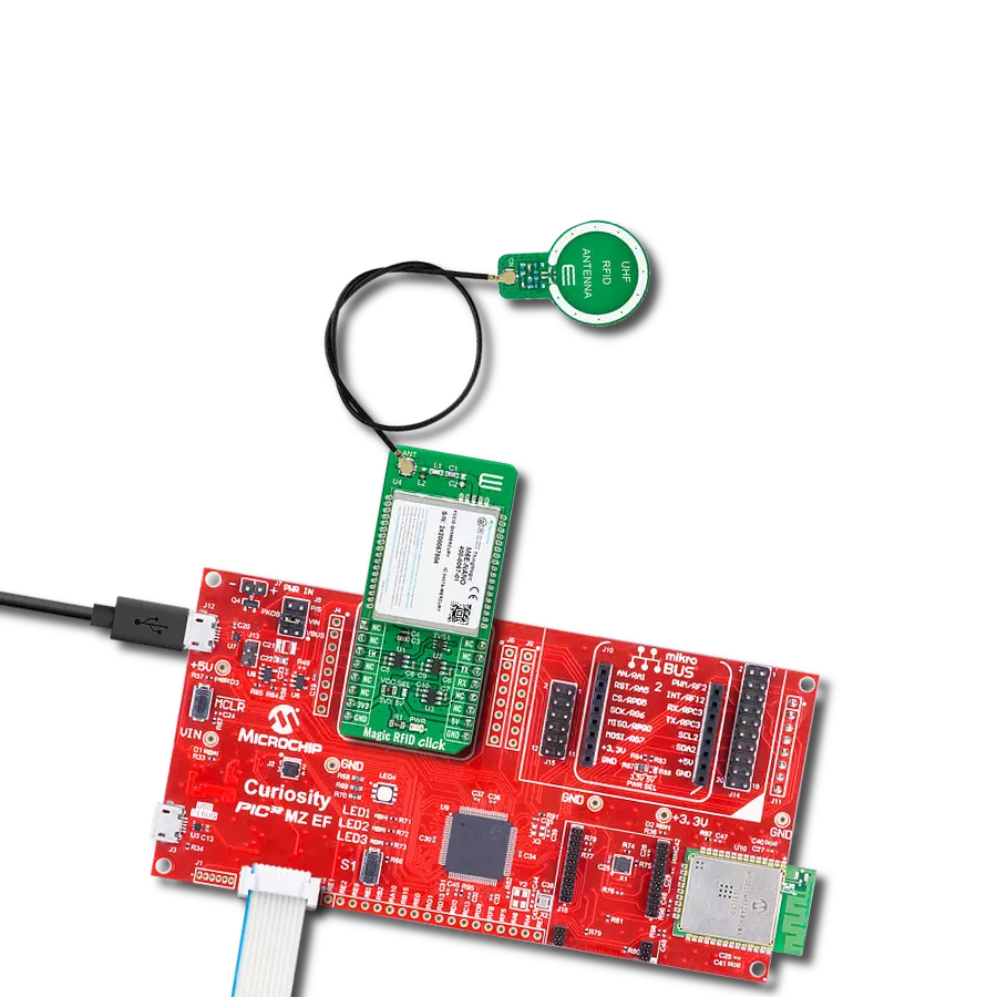
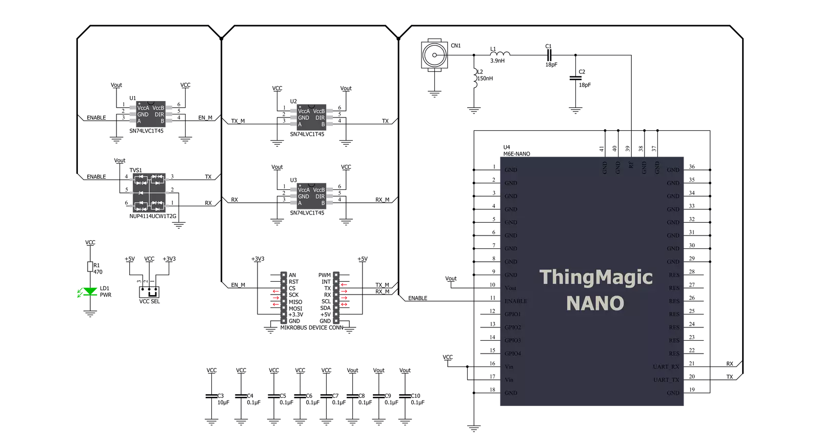
Magic RFID Click is based on the M6E-NANO, Ultra High Frequency embedded RFID module with ultra-low power consumption from JADAK. Supporting the EPC Gen2V2 and ISO 18000-63 standard, the M6E-NANO module is available for global use. It can be customized for frequencies in many global regions like the Americas, European Union (EU), India, Korea, Australia, China, and Japan. The ThingMagic‘s M6E-NANO module operates in the UHF band from 859MHz to 930MHz and is used for write/read applications. This module provides an output power of +27 dBm, adjustable in 0.01 dB steps with a read speed of 200 tags/sec, meaning that with the appropriate antenna and the configuration of the module itself, greater distances can be achieved (up to 4.5m). Magic RFID Click supports one monostatic bidirectional RF antenna through edge vias. The maximum RF power delivered to a 50Ω load from each port is 0.5W or +27 dBm. The performance of the module is affected by
antenna quality. Antennas that provide a 50Ω match at the operating frequency band perform best. Specified performance is achieved with antennas providing 17dB return loss or better across the operational range. Damage to the module will not occur for any return loss of 1dB. It may only occur if the antenna is disconnected during operation. The module communicates with MCU using a UART serial port supporting complete functionality except for the lowest power operational mode with a baud rate from 9600 to 921600bps. Upon initial Power-Up, the default baud rate of 115200 is used. The UART RX and TX lines are buffered with the SN74LVC1T45, a single-bit dual-supply bus transceiver with configurable voltage translation driven by the M6E-NANO Vout pin. This makes the inputs 5V tolerant and increases the output current driving capability from 10mA to 15mA. One TVS diode is added to the EN GPIO line to increase the ESD protection. Enable pin labeled as EN, routed on
the CS pin of the mikroBUS™ socket, must be pulled HIGH for the module to be operational. When this pin is in a LOW logic state, it turns the module off and reduces its power consumption to nearly zero. Magic RFID Click possesses a miniature coaxial N.FL series antenna connector that can be connected to the appropriate antenna that MIKROE offers, such as Circular UHF RFID Antenna. This antenna represents an excellent choice for all UHF/RFID applications that operate in a frequency range from 902MHz up to 928MHz. This Click board™ can operate with either 3.3V or 5V logic voltage levels selected via the VCC SEL jumper. This way, both 3.3V and 5V capable MCUs can use the communication lines properly. Also, this Click board™ comes equipped with a library containing easy-to-use functions and an example code that can be used as a reference for further development.


Features overview
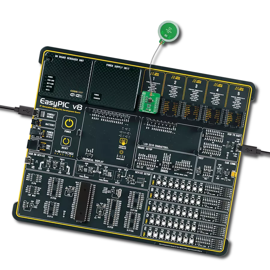
Development board
Curiosity PIC32 MZ EF development board is a fully integrated 32-bit development platform featuring the high-performance PIC32MZ EF Series (PIC32MZ2048EFM) that has a 2MB Flash, 512KB RAM, integrated FPU, Crypto accelerator, and excellent connectivity options. It includes an integrated programmer and debugger, requiring no additional hardware. Users can expand
functionality through MIKROE mikroBUS™ Click™ adapter boards, add Ethernet connectivity with the Microchip PHY daughter board, add WiFi connectivity capability using the Microchip expansions boards, and add audio input and output capability with Microchip audio daughter boards. These boards are fully integrated into PIC32’s powerful software framework, MPLAB Harmony,
which provides a flexible and modular interface to application development a rich set of inter-operable software stacks (TCP-IP, USB), and easy-to-use features. The Curiosity PIC32 MZ EF development board offers expansion capabilities making it an excellent choice for a rapid prototyping board in Connectivity, IOT, and general-purpose applications.

Microcontroller Overview
MCU Card / MCU

Architecture
PIC32
MCU Memory (KB)
2048
Silicon Vendor
Microchip
Pin count
100
RAM (Bytes)
524288
You complete me!
Accessories
UMCC - Ultraminiature Coax Connector is designed to address the escalating demand for miniaturization in next-generation wireless applications. With a cable diameter of 1.37mm and a length of 200mm, this ultra-low-profile coax female-to-female interconnect boasts a Type III connector with a mated height of just 2.5mm. The UMCC offers a characteristic impedance of 50 Ohms and an impressive frequency range from DC to 6GHz, ensuring optimal performance in various applications. Notably, its VSWR for mated pairs is 1.30 max from DC to 3GHz and 1.5 max from 3 to 6GHz (typical). The connectors exhibit a low insertion loss of 0.24dB max from DC to 6GHz. Featuring easy snap-on/off mating and a small 3x3mm footprint on PCBs, the UMCC is also compatible with Hirose U.FL series connectors, making it a versatile and efficient choice for compact, high-frequency connectivity needs.

A circular UHF RFID Antenna is a unique PCB near-field antenna designed to be used as an extension of development boards that uses electromagnetic fields most suitable for short-range communication. The antenna is designed in a circular shape with a diameter of 23mm. It's important to mention that this antenna can be used for UHF and RFID applications that operate in a frequency range from 902MHz up to 928MHz.

Used MCU Pins
mikroBUS™ mapper
Take a closer look
Click board™ Schematic
Step by step
Project assembly

Start by selecting your development board and Click board™. Begin with the Curiosity PIC32 MZ EF as your development board.


Software Support
Library Description
This library contains API for Magic RFID Click driver.
Key functions:
magicrfid_get_response- Magic RFID get response function.magicrfid_parse_tag_rssi- This function parses RSSI value of the tag.magicrfid_parse_tag_epc- This function parses EPC bytes of the tag.
Open Source
Code example
The complete application code and a ready-to-use project are available through the NECTO Studio Package Manager for direct installation in the NECTO Studio. The application code can also be found on the MIKROE GitHub account.
/*!
 * @file main.c
 * @brief Magic RFID Click Example.
 *
 * # Description
 * This example reads and processes data from Magic RFID Clicks.
 *
 * The demo application is composed of two sections :
 *
 * ## Application Init
 * Initialize driver init and starts default configuration module.
 *
 * ## Application Task
 * Scans for RFID TAGs and displays on the USB UART the EPC bytes of the detected tag.
 * It also parses and displays the RSSI as well as the frequency this tag was detected at.
 *
 * @author MikroE Team
 *
 */

#include "board.h"
#include "log.h"
#include "magicrfid.h"

static magicrfid_t magicrfid;
static log_t logger;

void application_init ( void )
{
    log_cfg_t log_cfg;  /**< Logger config object. */
    magicrfid_cfg_t magicrfid_cfg;  /**< Click config object. */

    /**
     * Logger initialization.
     * Default baud rate: 115200
     * Default log level: LOG_LEVEL_DEBUG
     * @note If USB_UART_RX and USB_UART_TX
     * are defined as HAL_PIN_NC, you will
     * need to define them manually for log to work.
     * See @b LOG_MAP_USB_UART macro definition for detailed explanation.
     */
    LOG_MAP_USB_UART( log_cfg );
    log_init( &logger, &log_cfg );
    log_info( &logger, " Application Init " );

    // Click initialization.
    magicrfid_cfg_setup( &magicrfid_cfg );
    MAGICRFID_MAP_MIKROBUS( magicrfid_cfg, MIKROBUS_1 );
    if ( UART_ERROR == magicrfid_init( &magicrfid, &magicrfid_cfg ) )
    {
        log_error( &logger, " Communication init." );
        for ( ; ; );
    }
    magicrfid_default_cfg ( &magicrfid );
    log_info( &logger, " Application Task " );
}

void application_task ( void )
{
    magicrfid_response_t rsp = { 0 };
    if ( ( MAGICRFID_OK == magicrfid_get_response ( &magicrfid, &rsp ) ) &&
         ( MAGICRFID_OPCODE_READ_TAG_ID_MULTIPLE == rsp.opcode ) )
    {
        if ( 0 == rsp.data_len )
        {
            log_printf( &logger, "\r\n --- SCANNING ---\r\n" );
        }
        else
        {
            log_printf( &logger, "\r\n --- TAG DETECTED ---\r\n" );
            int8_t tag_rssi = 0;
            uint32_t tag_freq = 0;
            magicrfid_epc_t epc = { 0 };
            tag_rssi = magicrfid_parse_tag_rssi ( rsp );
            log_printf( &logger, " RSSI: %d\r\n", ( int16_t ) tag_rssi );
            tag_freq = magicrfid_parse_tag_freq ( rsp );
            log_printf( &logger, " FREQ: %lu\r\n", tag_freq );
            magicrfid_parse_tag_epc ( rsp, &epc );
            log_printf( &logger, " EPC PC: 0x%.4X\r\n", epc.epc_pc );
            log_printf( &logger, " EPC ID (len: %u): ", ( uint16_t ) epc.data_len );
            for ( uint8_t cnt = 0; cnt < epc.data_len; cnt++ )
            {
                log_printf( &logger, "%.2X", ( uint16_t ) epc.data_buf[ cnt ] );
            }
            log_printf( &logger, "\r\n EPC CRC: 0x%.4X\r\n", epc.epc_crc );
            Delay_ms ( 100 );
            magicrfid_clear_buffers ( &magicrfid );
        }
    }
}

int main ( void )
{
    /* Do not remove this line or clock might not be set correctly. */
    #ifdef PREINIT_SUPPORTED
    preinit();
    #endif

    application_init( );

    for ( ; ; )
    {
        application_task( );
    }

    return 0;
}

// ------------------------------------------------------------------------ END
Additional Support
Resources
Category:RFID/NFC