Experience sound like never before with VS1053 and PIC32MZ2048EFM100
Unleash your soundtrack: Your ultimate MP3 solution!

Published Nov 02, 2023
Click board™
MP3 Click
Dev. board
Curiosity PIC32 MZ EF
Compiler
NECTO Studio
MCU
PIC32MZ2048EFM100
Say goodbye to format compatibility issues and focus on what matters most – enjoying your favorite tunes, no matter the file type
A
A
Hardware Overview
How does it work?
MP3 Click is based on the VS1053, an Ogg Vorbis, MP3, AAC, WMA, FLAC, and MIDI audio codec chip from VLSI Solution. It is a versatile MP3 decoder/encoder chip that belongs to VLSI Solution's extensive audio processor family and can decode even newer AAC files. It can decode MPEG 1 and MPEG 2 audio layer III (CBR+VBR+ABR) as parts of the MP3 format, MP1, and MP2, MPEG 4, WAV, General MIDI, and FLAC lossless audio with software plugins up to 24bits and 48KHz. The stereo earphone driver can drive a 30Ω load and has zero-cross detection for smooth volume change. The streaming support for MP3 and WAV, EarSpeaker spatial processing, bass, and treble controls are also included. The VS1053 can encode three different formats from a microphone connector in mono or stereo. Those
formats are lossless 16-bit PCM, IMA ADPSM, and a highly compressed, high-quality Ogg Vorbis with a software plugin. Users can easily implement microcontroller software to read MP3 files chunk by chunk and send them the same way to the host MCU. The MP3 Click receives its input bitstream through a serial input bus, which it listens to as a system peripheral. The input stream is decoded and passed through a digital volume control to an 18-bit oversampling, multi-bit, sigma-delta DAC. The decoding is controlled via a serial control bus. In addition to the basic decoding, adding application-specific features, like DSP effects, to the user RAM is possible. The MP3 Click uses an SPI serial interface to communicate with the host MCU. The SPI is used for both the chip's serial data interface (SDI) and serial control interface
(SCI). The DCS (data chip select) pin forces the serial interface into Standby mode while the chip is activated with a low logic state. In addition, the codec chip can be reset over the RST pin. The data request pin (DREQ) signals if VS1503's 2048-byte FIFO can receive data. It may turn LOW or HIGH anytime, even during a byte transmission. It should be only used to decide whether to send more bytes, while the transmission that has already started doesn't have to be aborted. This Click board™ can be operated only with a 3.3V logic voltage level. The board must perform appropriate logic voltage level conversion before using MCUs with different logic levels. Also, it comes equipped with a library containing functions and an example code that can be used as a reference for further development.

Features overview
Development board
Curiosity PIC32 MZ EF development board is a fully integrated 32-bit development platform featuring the high-performance PIC32MZ EF Series (PIC32MZ2048EFM) that has a 2MB Flash, 512KB RAM, integrated FPU, Crypto accelerator, and excellent connectivity options. It includes an integrated programmer and debugger, requiring no additional hardware. Users can expand
functionality through MIKROE mikroBUS™ Click™ adapter boards, add Ethernet connectivity with the Microchip PHY daughter board, add WiFi connectivity capability using the Microchip expansions boards, and add audio input and output capability with Microchip audio daughter boards. These boards are fully integrated into PIC32’s powerful software framework, MPLAB Harmony,
which provides a flexible and modular interface to application development a rich set of inter-operable software stacks (TCP-IP, USB), and easy-to-use features. The Curiosity PIC32 MZ EF development board offers expansion capabilities making it an excellent choice for a rapid prototyping board in Connectivity, IOT, and general-purpose applications.

Microcontroller Overview
MCU Card / MCU

Architecture
PIC32
MCU Memory (KB)
2048
Silicon Vendor
Microchip
Pin count
100
RAM (Bytes)
524288
You complete me!
Accessories
These standard small stereo earphones offer a high-quality listening experience with their top-notch stereo cable and connector. Designed for universal compatibility, they effortlessly connect to all MIKROE mikromedia and multimedia boards, making them an ideal choice for your electronic projects. With a rated power of 100mW, the earphones provide crisp audio across a broad frequency range from 20Hz to 20kHz. They boast a sensitivity of 100 ± 5dB and an impedance of 32Ω ± 15%, ensuring optimal sound quality. The Φ15mm speaker delivers clear and immersive audio. Cost-effective and versatile, these earphones are perfect for testing your prototype devices, offering an affordable and reliable audio solution to complement your projects.

Used MCU Pins
mikroBUS™ mapper
Take a closer look
Click board™ Schematic

Step by step
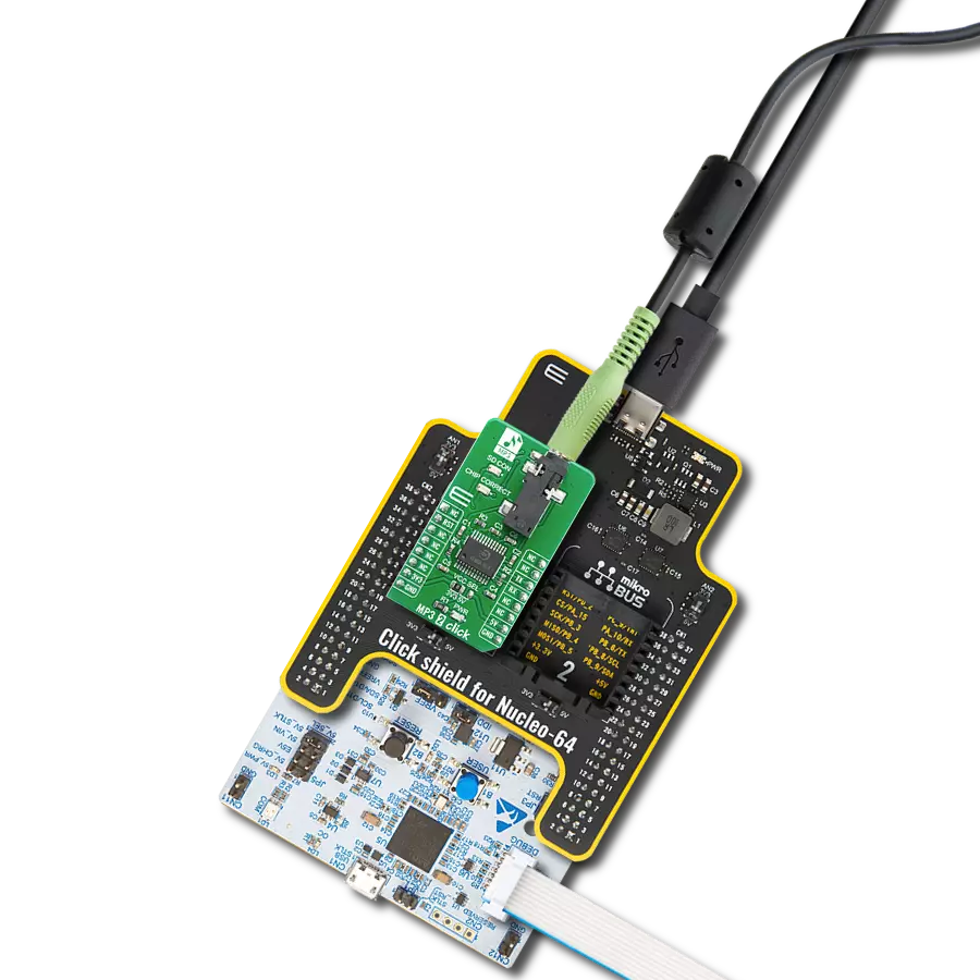
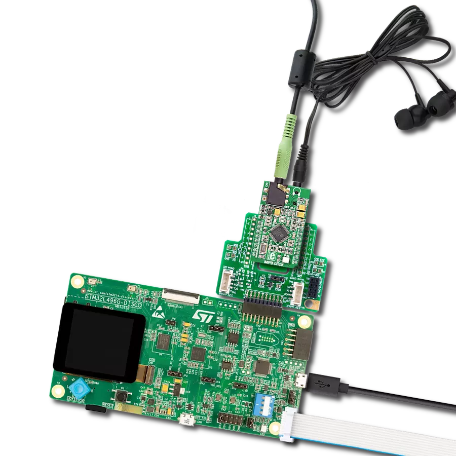
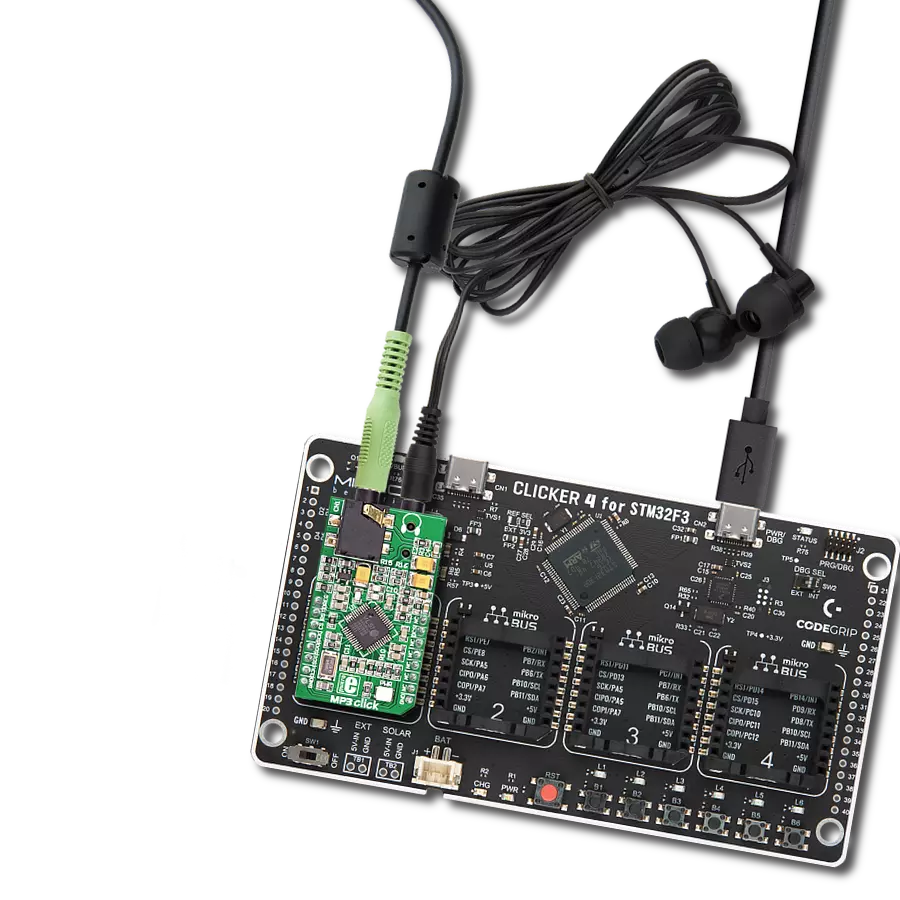
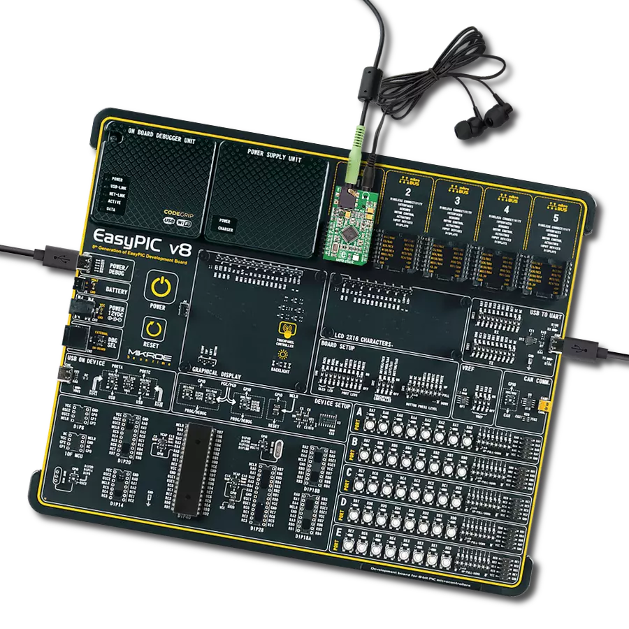
Project assembly

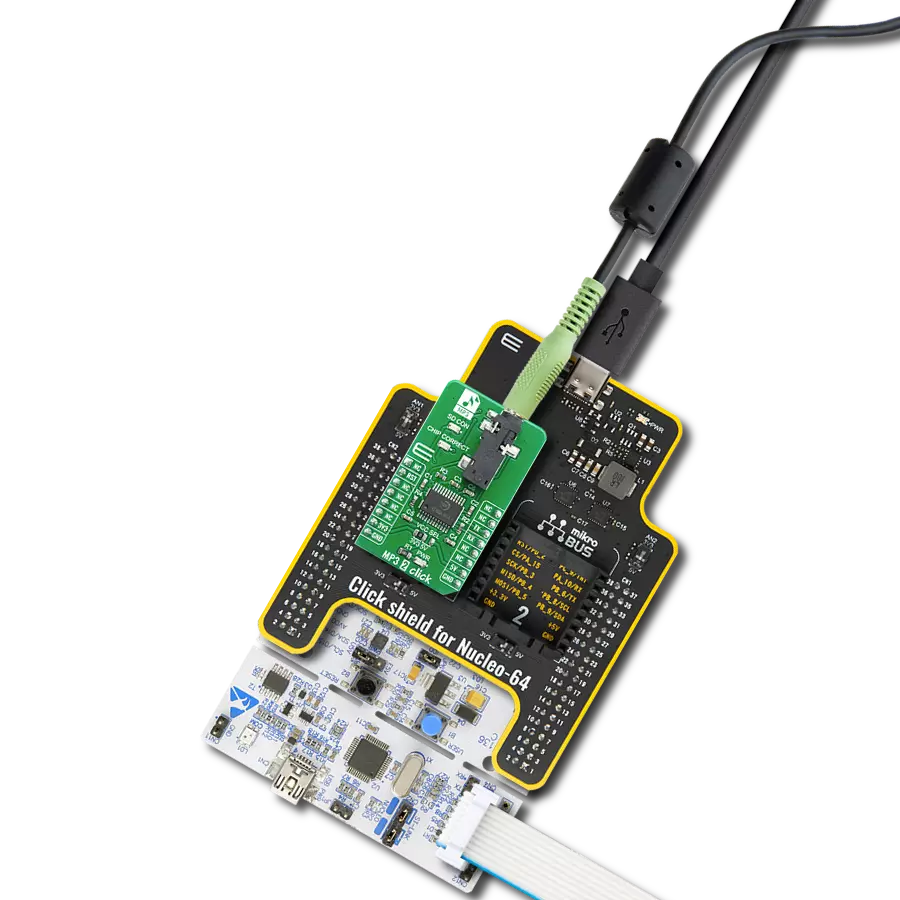
Start by selecting your development board and Click board™. Begin with the Curiosity PIC32 MZ EF as your development board.


Track your results in real time
Application Output
1. Application Output - In Debug mode, the 'Application Output' window enables real-time data monitoring, offering direct insight into execution results. Ensure proper data display by configuring the environment correctly using the provided tutorial.

2. UART Terminal - Use the UART Terminal to monitor data transmission via a USB to UART converter, allowing direct communication between the Click board™ and your development system. Configure the baud rate and other serial settings according to your project's requirements to ensure proper functionality. For step-by-step setup instructions, refer to the provided tutorial.

3. Plot Output - The Plot feature offers a powerful way to visualize real-time sensor data, enabling trend analysis, debugging, and comparison of multiple data points. To set it up correctly, follow the provided tutorial, which includes a step-by-step example of using the Plot feature to display Click board™ readings. To use the Plot feature in your code, use the function: plot(*insert_graph_name*, variable_name);. This is a general format, and it is up to the user to replace 'insert_graph_name' with the actual graph name and 'variable_name' with the parameter to be displayed.

Software Support
Library Description
This library contains API for MP3 Click driver.
Key functions:
mp3_cmd_write- This function writes one byte (command) to MP3 audio decodermp3_data_write- This function writes one byte ( data ) to MP3 audio decodermp3_data_write_32- This function Write 32 bytes ( data ) to MP3 audio decoder
Open Source
Code example
The complete application code and a ready-to-use project are available through the NECTO Studio Package Manager for direct installation in the NECTO Studio. The application code can also be found on the MIKROE GitHub account.
/*!
 * \file
 * \brief Mp3 Click example
 *
 * # Description
 * This app demonstrates the use of MP3 Click by playing the specified sound
 * from the mp3_resources.h file.
 *
 * The demo application is composed of two sections :
 *
 * ## Application Init
 * Initializes the driver and performs the default Click configuration.
 *
 * ## Application Task
 * Playing the specified sound form the mp3_resources.h file.
 *
 * \author MikroE Team
 *
 */

#include "board.h"
#include "log.h"
#include "mp3.h"
#include "mp3_resources.h"

static mp3_t mp3;
static log_t logger;

void application_init ( void )
{
    log_cfg_t log_cfg;
    mp3_cfg_t cfg;

    /**
     * Logger initialization.
     * Default baud rate: 115200
     * Default log level: LOG_LEVEL_DEBUG
     * @note If USB_UART_RX and USB_UART_TX
     * are defined as HAL_PIN_NC, you will
     * need to define them manually for log to work.
     * See @b LOG_MAP_USB_UART macro definition for detailed explanation.
     */
    LOG_MAP_USB_UART( log_cfg );
    log_init( &logger, &log_cfg );
    log_info( &logger, " Application Init " );

    // Click initialization.
    mp3_cfg_setup( &cfg );
    MP3_MAP_MIKROBUS( cfg, MIKROBUS_1 );
    mp3_init( &mp3, &cfg );

    mp3_reset( &mp3 );

    mp3_cmd_write( &mp3, MP3_MODE_ADDR, 0x0800 );
    mp3_cmd_write( &mp3, MP3_BASS_ADDR, 0x7A00 );
    mp3_cmd_write( &mp3, MP3_CLOCKF_ADDR, 0x2000 );

    // MP3 set volume, maximum volume is 0x00 and total silence is 0xFE.
    mp3_set_volume( &mp3, 0x2F, 0x2F );
    Delay_ms ( 1000 );

    log_info( &logger, " Application Task " );
}

void application_task ( void )
{
    uint32_t file_size = sizeof ( gandalf_sax_mp3_compressed );
    uint32_t file_pos = 0;
    uint8_t data_buf[ 32 ] = { 0 };

    log_printf( &logger, " Playing audio..." );
    for ( file_pos = 0; ( file_pos + 32 ) <= file_size; file_pos += 32 )
    {
        memcpy ( data_buf, &gandalf_sax_mp3_compressed[ file_pos ], 32 );
        while ( MP3_OK != mp3_data_write_32( &mp3, data_buf ) );
    }

    for ( ; file_pos < file_size; file_pos++ )
    {
        while ( MP3_OK != mp3_data_write( &mp3, gandalf_sax_mp3_compressed[ file_pos ] ) );
    }
    log_printf( &logger, "Done\r\n\n" );
}

int main ( void )
{
    /* Do not remove this line or clock might not be set correctly. */
    #ifdef PREINIT_SUPPORTED
    preinit();
    #endif

    application_init( );

    for ( ; ; )
    {
        application_task( );
    }

    return 0;
}


// ------------------------------------------------------------------------ END