Simplify and improve your I2C management needs using TCA9545A and PIC18F45K42
Switch, mux, and beyond
Published Sep 10, 2023
Click board™
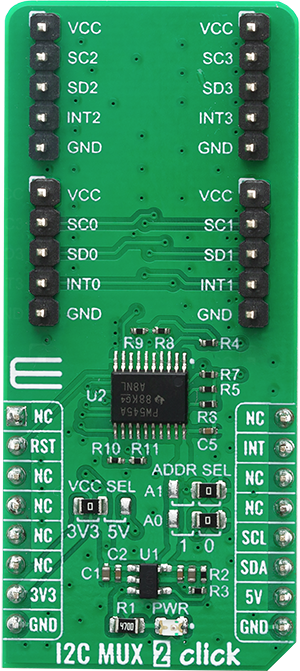
I2C MUX 2 Click
Dev. board
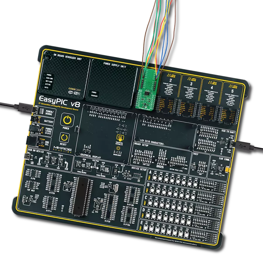
EasyPIC v8
Compiler
NECTO Studio
MCU
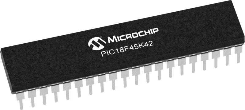
PIC18F45K42
Committed to enhancing your I2C communication capabilities, our mission is to provide seamless access to I2C multiplexing, offering a user-friendly and flexible solution for effectively addressing complex I2C scenarios
A
A
Hardware Overview
How does it work?
I2C MUX 2 Click is based on the TCA9545A, a 4-channel, bidirectional translating I2C switch from Texas instruments. The master SCL/SDA signal pair is directed to four channels of slave devices, SC0/SD0-SC3/SD3. Any individual downstream channel can be selected as well as any combination of the four channels. The TCA9545A also supports interrupt signals in order for the master to detect an interrupt on the INT output terminal that can result from any of the slave devices connected to the INT3-INT0 input terminals. The device offers an active-low RESET input which resets the state machine and allows the TCA9545A to recover should one of the downstream I2C buses get stuck in a low state. The state machine of the device can also be reset by cycling the power supply, VCC, also known as a power-on reset (POR). Both the RESET function and a POR will cause all channels to be deselected. The connections of the I2C data path are controlled by the same I2C master device that is switched to communicate with multiple I2C slaves. The I2C slave address can be configured by soldering SMD jumpers labeled as ADDR SEL to set the least significant bit (LSB). After the successful acknowledgment of the slave address, a single 8-bit control register is written to or read from to determine the selected channels and state
of the interrupts. The TCA9545A may also be used for voltage translation, allowing the use of different bus voltages on each SCn/SDn pair such that 1.8-V, 2.5-V, or 3.3-V parts can communicate with 5-V parts. This is achieved by using external pull-up resistors to pull the bus up to the desired voltage for the master and each slave channel. One or several SCn/SDn downstream pairs, or channels, are selected by the contents of the control register. After the TCA9545A has been addressed, the control register is written. The four LSBs of the control byte are used to determine which channel or channels are to be selected. When a channel is selected, it becomes active after a stop condition has been placed on the I2C bus. This ensures that all SCn/SDn lines are in a high state when the channel is made active so that no false conditions are generated at the time of connection. A stop condition must occur always right after the acknowledge cycle. The TCA9545A provides four interrupt inputs (one for each channel) and one open-drain interrupt output. When an interrupt is generated by any device, it is detected by the TCA9545A and the interrupt output is driven low. The channel does not need to be active for the detection of the interrupt. A bit also is set in the control register. Bits 4–7 of the control register correspond to channels 0–3 of the
TCA9545A, respectively. Therefore, if an interrupt is generated by any device connected to channel 1, the state of the interrupt inputs is loaded into the control register when a read is accomplished. Likewise, an interrupt on any device connected to channel 0 would cause bit 4 of the control register to be set on the read. The master then can address the TCA9545A and read the contents of the control register to determine which channel contains the device generating the interrupt. The master then can reconfigure the TCA9545A to select this channel and locate the device generating the interrupt and clear it. It should be noted that more than one device can provide an interrupt on a channel, so it is up to the master to ensure that all devices on a channel are interrogated for an interrupt. The interrupt inputs can be used as general-purpose inputs if the interrupt function is not required. If unused, interrupt input(s) must be connected to VCC. This Click board™ can operate with either 3.3V or 5V logic voltage levels selected via the VCC SEL jumper. This way, both 3.3V and 5V capable MCUs can use the communication lines properly. Also, this Click board™ comes equipped with a library containing easy-to-use functions and an example code that can be used as a reference for further development.


Features overview
Development board
EasyPIC v8 is a development board specially designed for the needs of rapid development of embedded applications. It supports many high pin count 8-bit PIC microcontrollers from Microchip, regardless of their number of pins, and a broad set of unique functions, such as the first-ever embedded debugger/programmer. The development board is well organized and designed so that the end-user has all the necessary elements, such as switches, buttons, indicators, connectors, and others, in one place. Thanks to innovative manufacturing technology, EasyPIC v8 provides a fluid and immersive working experience, allowing access anywhere and under any
circumstances at any time. Each part of the EasyPIC v8 development board contains the components necessary for the most efficient operation of the same board. In addition to the advanced integrated CODEGRIP programmer/debugger module, which offers many valuable programming/debugging options and seamless integration with the Mikroe software environment, the board also includes a clean and regulated power supply module for the development board. It can use a wide range of external power sources, including a battery, an external 12V power supply, and a power source via the USB Type-C (USB-C) connector.
Communication options such as USB-UART, USB DEVICE, and CAN are also included, including the well-established mikroBUS™ standard, two display options (graphical and character-based LCD), and several different DIP sockets. These sockets cover a wide range of 8-bit PIC MCUs, from the smallest PIC MCU devices with only eight up to forty pins. EasyPIC v8 is an integral part of the Mikroe ecosystem for rapid development. Natively supported by Mikroe software tools, it covers many aspects of prototyping and development thanks to a considerable number of different Click boards™ (over a thousand boards), the number of which is growing every day.

Microcontroller Overview
MCU Card / MCU
Architecture
PIC
MCU Memory (KB)
32
Silicon Vendor
Microchip
Pin count
40
RAM (Bytes)
2048
Used MCU Pins
mikroBUS™ mapper
Take a closer look
Click board™ Schematic

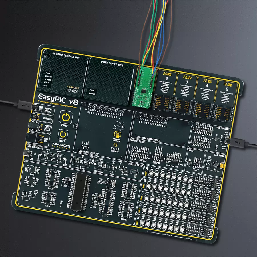
Step by step
Project assembly

Start by selecting your development board and Click board™. Begin with the EasyPIC v8 as your development board.


Software Support
Library Description
This library contains API for I2C MUX 2 Click driver.
Key functions:
i2cmux2_hw_reset- This function resets I2C MUX 2 click board by clearing the RST pin for 100msi2cmux2_set_channel- Function sets channel of the I2C MUX 2 click boardi2cmux2_generic_read- This function reads data from the desired register.
Open Source
Code example
The complete application code and a ready-to-use project are available through the NECTO Studio Package Manager for direct installation in the NECTO Studio. The application code can also be found on the MIKROE GitHub account.
/*!
 * \file
 * \brief I2cMux2 Click example
 *
 * # Description
 * This example demonstrates the use of the I2C MUX 2 Click board.
 *
 * The demo application is composed of two sections :
 *
 * ## Application Init
 * Initializes the driver, performs the device reset, and makes an initial log.
 *
 * ## Application Task
 * In this example, we read the device ID register of the connected Click boards.
 * Channel 0 : 6DOF IMU 11 Click [slave address: 0x0E; reg: 0x00; id val.: 0x2D],
 * Channel 1 : Altitude Click    [slave address: 0x60; reg: 0x0C; id val.: 0xC4],
 * Channel 2 : 6DOF IMU 9 Click  [slave address: 0x69; reg: 0x75; id val.: 0xA9],
 * Channel 3 : Compass 3 Click   [slave address: 0x30; reg: 0x2F; id val.: 0x0C].
 * All data logs write on USB UART changes every 2 sec.
 *
 * @note
 * Disable all unconnected channels from the example using ENABLE_CHANNEL_x macros
 * below to prevent the I2C bus from blocking waiting for a device response.
 *
 * \author MikroE Team
 *
 */
// ------------------------------------------------------------------- INCLUDES

#include "board.h"
#include "log.h"
#include "i2cmux2.h"

// ------------------------------------------------------------------ VARIABLES

// Comment out the following lines to exclude unconnected channels from the example
#define ENABLE_CHANNEL_0
#define ENABLE_CHANNEL_1
#define ENABLE_CHANNEL_2
#define ENABLE_CHANNEL_3

static i2cmux2_t i2cmux2;
static log_t logger;
static uint8_t rx_data;

// ------------------------------------------------------- ADDITIONAL FUNCTIONS

void display_log ( uint8_t sel_ch )
{
    switch ( sel_ch )
    {
        case I2CMUX2_CMD_SET_CH_0:
        {
            log_printf( &logger, "   0  |  " );
            break;
        }
        case I2CMUX2_CMD_SET_CH_1:
        {
            log_printf( &logger, "   1  |  " );
            break;
        }
        case I2CMUX2_CMD_SET_CH_2:
        {
            log_printf( &logger, "   2  |  " );
            break;
        }
        case I2CMUX2_CMD_SET_CH_3:
        {
            log_printf( &logger, "   3  |  " );
            break;
        }
        default:
            break;
    }
    log_printf( &logger, "0x%.2X", ( uint16_t ) rx_data );

    if ( i2cmux2_check_int( &i2cmux2 ) == I2CMUX2_INT_PIN_STATE_ACTIVE )
    {
        if ( i2cmux2_read_interrupt( &i2cmux2 ) & sel_ch  )
        {
            log_printf( &logger, "  |  ON \r\n" );
        }
        else
        {
            log_printf( &logger, "  | OFF \r\n" );
        }
    }
    else
    {
        log_printf( &logger, "  | OFF \r\n" );
    }
}

// ------------------------------------------------------ APPLICATION FUNCTIONS

void application_init ( void )
{
    log_cfg_t log_cfg;
    i2cmux2_cfg_t cfg;

    /**
     * Logger initialization.
     * Default baud rate: 115200
     * Default log level: LOG_LEVEL_DEBUG
     * @note If USB_UART_RX and USB_UART_TX
     * are defined as HAL_PIN_NC, you will
     * need to define them manually for log to work.
     * See @b LOG_MAP_USB_UART macro definition for detailed explanation.
     */
    LOG_MAP_USB_UART( log_cfg );
    log_init( &logger, &log_cfg );
    log_info( &logger, "---- Application Init ----" );

    //  Click initialization.
    i2cmux2_cfg_setup( &cfg );
    I2CMUX2_MAP_MIKROBUS( cfg, MIKROBUS_1 );
    i2cmux2_init( &i2cmux2, &cfg );

    Delay_ms ( 100 );
    log_printf( &logger, "I2C MUX 2 Click driver init\r\n");
    log_printf( &logger, "---------------------------------------\r\n");
    Delay_ms ( 100 );

    i2cmux2_hw_reset( &i2cmux2 );
    log_printf( &logger, "I2C MUX 2 Click HW reset\r\n");
    log_printf( &logger, "---------------------------------------\r\n");
    Delay_ms ( 100 );
}

void application_task ( void )
{
    log_printf( &logger, "  CH  |   ID   |  INT \r\n" );
    log_printf( &logger, "----------------------\r\n" );

#ifdef ENABLE_CHANNEL_0
    // SET CHANNEL 0: 6DOF IMU 11 Click
    i2cmux2_set_channel( &i2cmux2, I2CMUX2_CMD_SET_CH_0, 0x0E );
    Delay_ms ( 100 );
    i2cmux2_generic_read( &i2cmux2, 0x00, &rx_data, 1 );
    display_log( I2CMUX2_CMD_SET_CH_0 );
#endif

#ifdef ENABLE_CHANNEL_1
    // SET CHANNEL 1: Altitude Click
    i2cmux2_set_channel( &i2cmux2, I2CMUX2_CMD_SET_CH_1, 0x60 );
    Delay_ms ( 100 );
    i2cmux2_generic_read( &i2cmux2, 0x0C, &rx_data, 1 );
    display_log( I2CMUX2_CMD_SET_CH_1 );
#endif

#ifdef ENABLE_CHANNEL_2
    // SET CHANNEL 2: 6DOF IMU 9 Click
    i2cmux2_set_channel( &i2cmux2, I2CMUX2_CMD_SET_CH_2, 0x69 );
    Delay_ms ( 100 );
    i2cmux2_generic_read( &i2cmux2, 0x75, &rx_data, 1 );
    display_log( I2CMUX2_CMD_SET_CH_2 );
#endif

#ifdef ENABLE_CHANNEL_3
    // SET CHANNEL 3: Compass 3 Click
    i2cmux2_set_channel( &i2cmux2, I2CMUX2_CMD_SET_CH_3, 0x30 );
    Delay_ms ( 100 );
    i2cmux2_generic_read( &i2cmux2, 0x2F, &rx_data, 1 );
    display_log( I2CMUX2_CMD_SET_CH_3 );
#endif

    log_printf( &logger, "----------------------\r\n" );
    Delay_ms ( 1000 );
    Delay_ms ( 1000 );
}

int main ( void )
{
    /* Do not remove this line or clock might not be set correctly. */
    #ifdef PREINIT_SUPPORTED
    preinit();
    #endif

    application_init( );

    for ( ; ; )
    {
        application_task( );
    }

    return 0;
}


// ------------------------------------------------------------------------ END


